tow Hyundai Matrix 2005 Owner's Manual
[x] Cancel search | Manufacturer: HYUNDAI, Model Year: 2005, Model line: Matrix, Model: Hyundai Matrix 2005Pages: 407, PDF Size: 10.31 MB
Page 1 of 407
SA000A1-E
This Owners Manual should be considered a part of the car and remain with it when it is sold for the use of the next owner.
OWNER I.D.
ORIGINAL: ADDRESS: DATE OF SALE: SUBSEQUENT: ADDRESS: TRANSFER DATE: NAME: STREET:TOWN:COUNTRY:P.CODE: NAME: STREET:TOWN:COUNTRY:P.CODE:
Page 10 of 407
CONTROLS AND EQUIPMENT
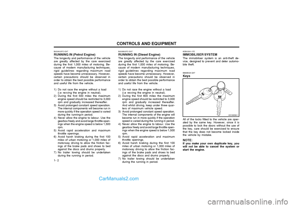
1- 2 6SB035A1-FE IMMOBILISER SYSTEM The immobiliser system is an anti-theft de- vice, designed to prevent and deter automo-bile theft. B880B03A-GAT Keys All of the locks fitted to the vehicle are oper- ated by the same key. However, since it ispossible to lock the doors without the use ofthe key, care should be exercised to ensurethat the key does not become locked insidethe vehicle by mistake. NOTE: If you make your own duplicate key, you will not be able to cancel the system orstart the engine.
B020A02FC-EAT RUNNING IN (Petrol Engine) The longevity and performance of the vehicle are greatly affected by the care exercisedduring the first 1,000 miles of motoring. Be-cause of modern manufacturing techniques,rigid guidelines regarding maximum roadspeeds have become unnecessary. However,certain precautions should be observed inorder to obtain the best possible performanceand useful life from the vehicle.
1) Do not race the engine without a load
(i.e revving the engine in neutral).
2) During the first 500 miles the maximum engine speed should be restricted to 3,000 rpm and gradually increased thereafter.
3) Avoid prolonged constant speed operation. The internal components will become run in
more quickly if the operation speed is varied
during the running-in period.
4) Never allow the engine to labour. Use the gearbox freely and avoid large throttle open-ings when the engine speed is below 1,500rpm.
5) Avoid rapid acceleration and maximum throttle openings.
6) Avoid harsh braking during the first 100 miles of urban motoring or 1,000 miles ofmotorway driving to allow the friction fac-ings of the brake pads and shoes to bedagainst the discs and drums properly.
7) No trailer towing should be undertaken during the running in period.
AX10020A-1
B020B02FC-EAT
RUNNING IN (Diesel Engine)
The longevity and performance of the vehicle
are greatly affected by the care exercised during the first 1,000 miles of motoring. Be-cause of modern manufacturing techniques,rigid guidelines regarding maximum roadspeeds have become unnecessary. However,certain precautions should be observed inorder to obtain the best possible performanceand useful life from the vehicle.
1) Do not race the engine without a load
(i.e revving the engine in neutral).
2) During the first 600 miles the maximum engine speed should be restricted to 3,000 rpm and gradually increased thereafter.And whilst driving, keep under three quar-ters of maximum vehicle speed.
3) Avoid prolonged constant speed operation. The internal components of the engine willbecome run in more quickly if the operationspeed is varied during the running in period.
4) Never allow the engine to labour. Use the gearbox freely and avoid large throttle open-ings when the engine speed is below 1,500rpm.
5) Avoid rapid acceleration and maximum throttle openings.
6) Avoid harsh braking during the first 100 miles of urban motoring or 1,000 miles ofmotorway driving to allow the friction fac-ings of the brake pads and shoes to bedagainst the discs and drums properly.
7) No trailer towing should be undertaken during the running in period.
Page 11 of 407
1- 3
CONTROLS AND EQUIPMENT
B880C02A-GAT
Key Numbers
The vehicle key number is recorded upon a
metal tag attached to the keys when the vehicle is first delivered to you. The key number should be recorded and kept
in a safe place in case the need to orderfurther keys arises. New keys are availablefrom any Hyundai authorised repairer byquoting the relevant key number.
In the interest of security, the metal tag
attached to the keys which bears the keynumber should be removed from the key ringafter you receive your new vehicle. In addi-tion, key numbers cannot be provided byHyundai for security reasons.
If you need additional keys or if you should
lose your keys, your Hyundai authorisedrepairer can make new keys. SB040B1-F Locking, unlocking front doors with key
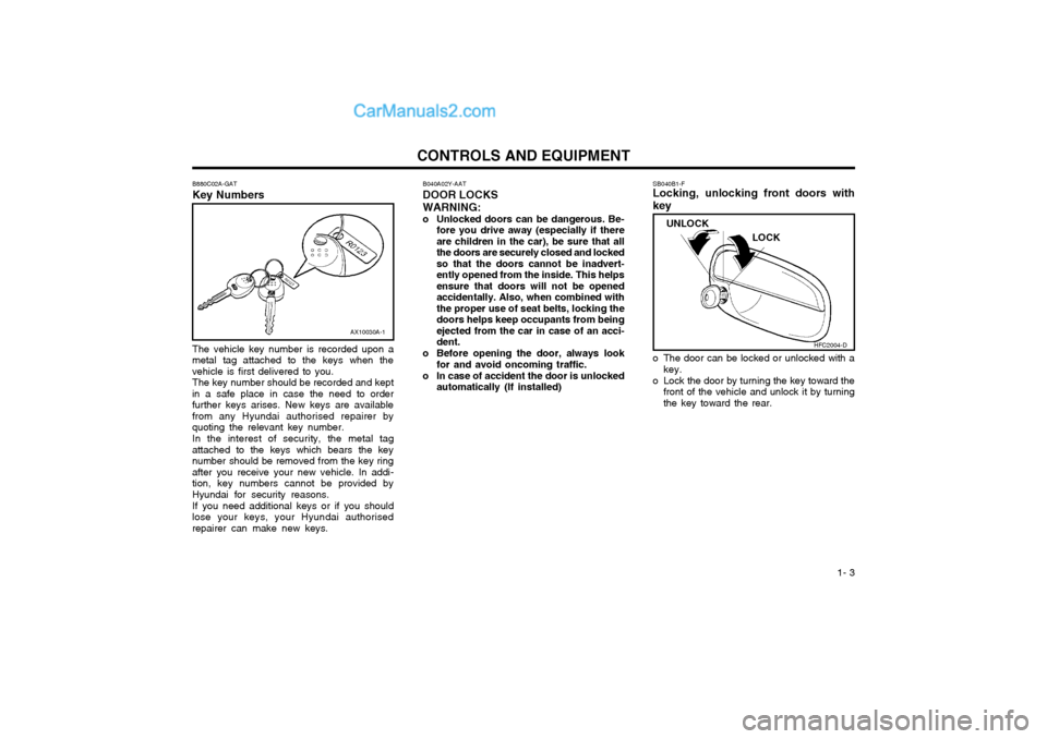
o The door can be locked or unlocked with a
key.
o Lock the door by turning the key toward the front of the vehicle and unlock it by turning the key toward the rear.
AX10030A-1
B040A02Y-AAT DOOR LOCKS WARNING:
o Unlocked doors can be dangerous. Be- fore you drive away (especially if there are children in the car), be sure that allthe doors are securely closed and lockedso that the doors cannot be inadvert-ently opened from the inside. This helpsensure that doors will not be openedaccidentally. Also, when combined withthe proper use of seat belts, locking thedoors helps keep occupants from beingejected from the car in case of an acci-dent.
o Before opening the door, always look for and avoid oncoming traffic.
o In case of accident the door is unlocked automatically (If installed)
LOCK
UNLOCK
HFC2004-D
Page 13 of 407
1- 5
CONTROLS AND EQUIPMENT
SB040G1-F
CENTRAL DOOR LOCK (Not all models) The central door locking is operated by push-
ing the driver's door lock switch toward the front or rear of the vehicle. If the passenger andrear doors are open when the switch is pushed,the door will remain locked when closed.
NOTE:
o When pushing the switch toward the rear, all doors and tail gate will unlock. When pushing the switch toward the front, all doors and tail gate will lock.
o When the door is unlocked, the red mark on the switch is visible and the character"LOCK" on the switch is visible.
o The central door locking is operated by turning the key (with theft-alarm system:driver's door and passenger's door, with-out theft-alarm system: driver's door only)toward the front or rear of the vehicle. B070A01A-EAT
ANTI-THEFT ALARM SYSTEM (Not all models)
This system is designed to provide protection
from unauthorised entry into the car. This system is operated in three stages: the first isthe "Armed" stage, the second is the "Alarm" stage, and the third is the "Disarmed" stage. If triggered, the system provides an audiblealarm with blinking of the turn signal lights.
HFC2003-D
LOCK
UNLOCK
B040G01FC-D
B070B01O-DAT
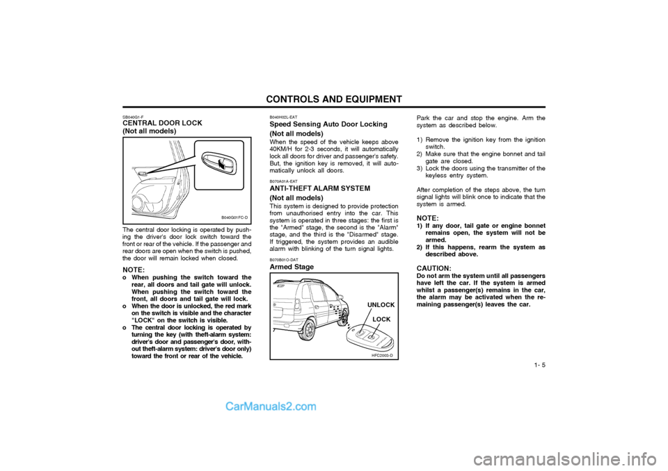
Armed Stage Park the car and stop the engine. Arm the system as described below.
1) Remove the ignition key from the ignition
switch.
2) Make sure that the engine bonnet and tail gate are closed.
3) Lock the doors using the transmitter of the keyless entry system.
After completion of the steps above, the turn signal lights will blink once to indicate that thesystem is armed. NOTE:
1) If any door, tail gate or engine bonnet remains open, the system will not be armed.
2) If this happens, rearm the system as described above.
CAUTION: Do not arm the system until all passengers have left the car. If the system is armedwhilst a passenger(s) remains in the car,the alarm may be activated when the re-maining passenger(s) leaves the car.
B040H02L-EAT
Speed Sensing Auto Door Locking (Not all models)
When the speed of the vehicle keeps above
40KM/H for 2-3 seconds, it will automatically lock all doors for driver and passenger's safety.
But, the ignition key is removed, it will auto-
matically unlock all doors.
Page 19 of 407
1- 11
CONTROLS AND EQUIPMENT
B090A01FC
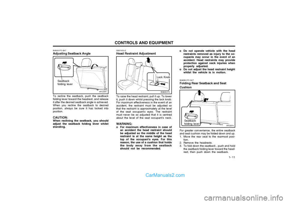
Lock Knob
SB070D3-E Head Restraint Adjustment To raise the head restraint, pull it up. To lower it, push it down whilst pressing the lock knob.For maximum effectiveness in the event of anaccident, the restraint must be adjusted sothat the restraint is approximately at the levelof the seat occupant's eyes. The restraintmust never be so adjusted that it is centredabout the level of the seat occupant's neck. WARNING:
o For maximum effectiveness in case of
an accident the head restraint shouldbe adjusted so the middle of the headrestraint is at the same height as thetop of the occupant's eyes. For thisreason, the use of a cushion that holdsthe body away from the seatbackshould not be recommended.
B080I01FC-BAT
Adjusting Seatback Angle
HFC2061
To recline the seatback, push the seatback
folding lever toward the headrest, and release it after the desired seatback angle is achieved.
When you recline the seatback to desired
position, always be sure it has locked intoposition.
CAUTION:When reclining the seatback, you should
adjust the seatback folding lever whilststanding. B090B01FC-GAT Folding Rear Seatback and Seat Cushion
HFC2074
Seatback folding lever
For greater convenience, the entire seatback and seat cushion may be folded down and up.
1. Move the rear seat to the rearmost posi- tion.
2. Remove the headrests.
3. To fold down the seatback , push and hold the seatback folding lever toward the head- rest, then push down the seatback.
Seatback folding lever
o Do not operate vehicle with the head
restraints removed as injury to the oc- cupants may occur in the event of anaccident. Head restraints may provideprotection against neck injuries whenproperly adjusted.
o Do not adjust the head restraint height whilst the vehicle is in motion.
Page 22 of 407
CONTROLS AND EQUIPMENT
1- 14 SB090P1-E
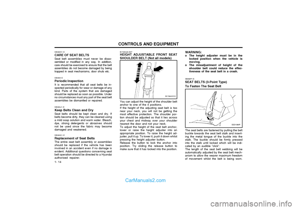
SEAT BELTS (3-Point Type) To Fasten The Seat Belt
SSD1090P
The seat belts are fastened by pulling the belt
buckle towards the seat belt stalk and insert- ing the metal tongue of the buckle into thestalk. The buckle should be firmly pressedinto the stalk until locked which will be indi-cated by an audible "click".
The length of the seat belt webbing will be
automatically adjusted by the seat belt mech-anism to allow the wearer maximum freedomof movement whilst the belt is being worn. WARNING:
o The height adjuster must be in the locked position when the vehicle ismoving.
o The misadjustment of height of the shoulder belt could reduce the effec-tiveness of the seat belt in a crash.
B170A01E-D
B170A04A-EAT HEIGHT ADJUSTABLE FRONT SEAT SHOULDER BELT (Not all models) You can adjust the height of the shoulder belt anchor to one of the 4 positions. If the height of the adjusting seat belt is too near your neck, you will not be getting themost effective protection. The shoulder por-tion should be adjusted so that it lies acrossyour chest and midway over your shouldernearest the door and not your neck. To adjust the height of the seat belt anchor, lower or raise the height adjuster into anappropriate position. To raise the height ad-juster, pull it up. To lower it, push it down whilstpressing the height adjuster button. Release the button to lock the anchor into position. Try sliding the release button tomake sure that it has locked into the position.
SB090H1-E
CARE OF SEAT BELTS
Seat belt assemblies must never be disas-
sembled or modified in any way. In addition,care should be exercised to ensure that the beltassemblies do not become damaged by beingtrapped in seat mechanisms, door shuts etc.
SB090I-E Periodic InspectionIt is recommended that all seat belts be in- spected periodically for wear or damage of anykind. Parts of the system that are damagedshould be replaced as soon as possible. Underno circumstances must any part of the seat beltassemblies be dismantled or repaired. SB090J1-E Keep Belts Clean and Dry Seat belts should be kept clean and dry. If belts become dirty, they can be cleaned usinga mild soap solution and warm water. Bleach,dye, strong detergents or abrasives shouldnot be used since the fabric may becomedamaged and weakened. SB090K1-E Replacement of Seat Belts The entire seat belt assembly or assemblies should be replaced if the vehicle has beeninvolved in an accident even if no damage isevident. Additional questions concerning seatbelt operation should be directed to a Hyundaiauthorised repairer.
Page 27 of 407
1- 19
CONTROLS AND EQUIPMENT
B230G01A-GAT
Installation on Outboard Rear Seats move it in all directions to be sure the child restraint system is securely installed. If you need to tighten the belt, pull more webbing toward the retractor. When you un-buckle the seat belt and allow it to retract, theretractor will automatically revert back to itsnormal seated passenger emergency lockingusage condition. NOTE:
o Before installing the child restraint
system, read the instructions supplied by the child restraint system manufac-turer.
o If the seat belt does not operate as described, have the system checkedimmediately by your Hyundaiauthorised repairer.
WARNING:Do not install any child restraint system inthe front passenger seat. Should an acci-dent occur and cause the passenger sideairbag to deploy, it could severely injureor kill an infant or child seated in an infantor child seat. Therefore, only use a childrestraint system in the rear seat of yourvehicle.
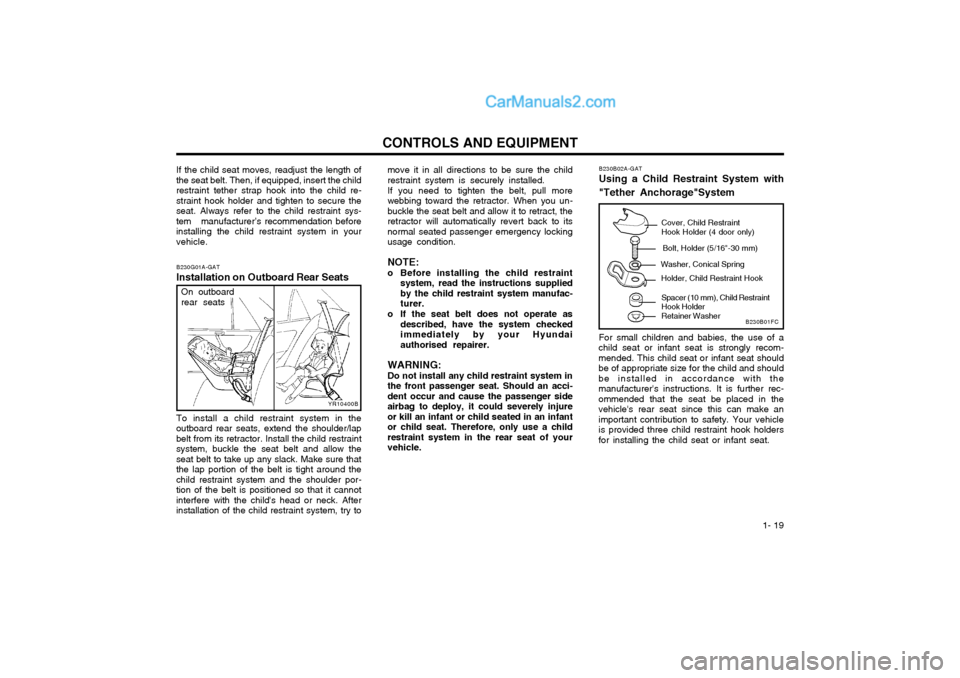
To install a child restraint system in the
outboard rear seats, extend the shoulder/lapbelt from its retractor. Install the child restraintsystem, buckle the seat belt and allow theseat belt to take up any slack. Make sure thatthe lap portion of the belt is tight around thechild restraint system and the shoulder por-tion of the belt is positioned so that it cannotinterfere with the child's head or neck. Afterinstallation of the child restraint system, try to
YR10400B
On outboard rear seats
B230B02A-GAT Using a Child Restraint System with "Tether Anchorage"System For small children and babies, the use of a
child seat or infant seat is strongly recom- mended. This child seat or infant seat shouldbe of appropriate size for the child and shouldbe installed in accordance with themanufacturer's instructions. It is further rec-ommended that the seat be placed in thevehicle's rear seat since this can make animportant contribution to safety. Your vehicleis provided three child restraint hook holdersfor installing the child seat or infant seat.
Cover, Child Restraint Hook Holder (4 door only)
Bolt, Holder (5/16"-30 mm)
Washer, Conical Spring Holder, Child Restraint Hook
Spacer (10 mm), Child Restraint Hook Holder Retainer Washer
B230B01FC
If the child seat moves, readjust the length of
the seat belt. Then, if equipped, insert the child restraint tether strap hook into the child re-straint hook holder and tighten to secure theseat. Always refer to the child restraint sys-tem manufacturer’s recommendation beforeinstalling the child restraint system in yourvehicle.
Page 36 of 407
CONTROLS AND EQUIPMENT
1- 28
o For cleaning the airbag pad covers,
use only a soft, dry cloth or one which has been moistened with plain water.Solvents or cleaners could adverselyaffect the airbag covers and properdeployment of the system.
o No objects should be placed over or near the airbag modules on the steeringwheel, instrument panel, and the frontpassenger's panel above the glove box,because any such object could causeharm if the vehicle is in a crash severeenough to cause the airbags to inflate.
o If the airbags inflate, they must be re- placed by an Hyundai authorised re-pairer.
o Do not tamper with or disconnect SRS wiring, or other components of the SRSsystem. Doing so could result in injury,due to accidental firing of the airbags orby rendering the SRS inoperative.
o If components of the airbag system must be discarded, or if the vehicle must bescrapped, certain safety precautionsmust be observed. Your Hyundai dealerknows these precautions and can giveyou the necessary information. Failureto follow these precautions and proce-dures could increase the risk of per-sonal injury. o If you sell your vehicle, be sure to
inform the new owner of these impor-tant points and make certain that thismanual is transferred to the new owner.
o If your car was flooded and has soaked carpeting or water on flooring, youshouldn't try to start engine; have thecar towed to Hyundai authorised re-pairer.
o Do not replace the bumper or the bumper guard with the one other thanthe Hyundai genuine parts. Otherwise,it can adversely affect SRS performanceand lead to unexpected injury.
Page 41 of 407
1- 33
CONTROLS AND EQUIPMENTcircuits becoming defective, approximately fifty per cent of the normal braking perfor-mance will be available. If failure of one of the circuits occurs, the required amount of pedal effort, pedal traveland stopping distance will be increased. Useof the gearbox is recommended to assist inbringing the vehicle to rest. The vehicle mustnot be driven once brake failure has occurreduntil the system has been repaired and isfunctioning normally. The braking system employs a vacuum servo in order that the pedal efforts are reduced.Power for the servo is derived from the engineand therefore, in the event of the enginestopping or the vehicle being towed, pedalefforts will be substantially increased.
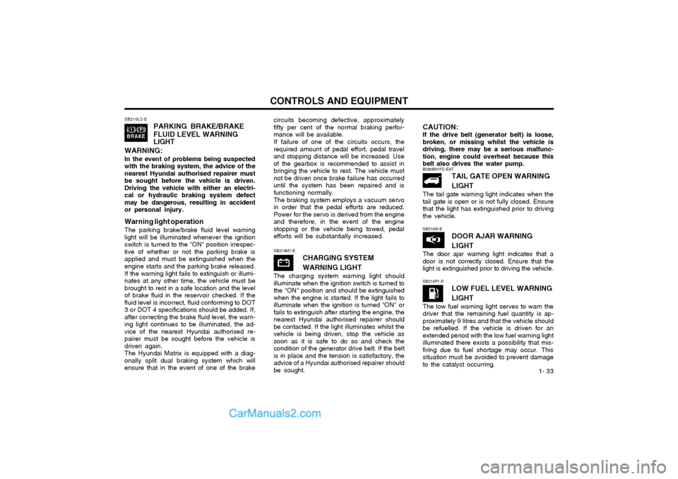
SB210L2-E
PARKING BRAKE/BRAKE FLUID LEVEL WARNING LIGHT
WARNING: In the event of problems being suspected with the braking system, the advice of thenearest Hyundai authorised repairer mustbe sought before the vehicle is driven.Driving the vehicle with either an electri-cal or hydraulic braking system defectmay be dangerous, resulting in accidentor personal injury. Warning light operation The parking brake/brake fluid level warning light will be illuminated whenever the ignitionswitch is turned to the "ON" position irrespec-tive of whether or not the parking brake isapplied and must be extinguished when theengine starts and the parking brake released. If the warning light fails to extinguish or illumi- nates at any other time, the vehicle must bebrought to rest in a safe location and the levelof brake fluid in the reservoir checked. If thefluid level is incorrect, fluid conforming to DOT3 or DOT 4 specifications should be added. If,after correcting the brake fluid level, the warn-ing light continues to be illuminated, the ad-vice of the nearest Hyundai authorised re-pairer must be sought before the vehicle isdriven again.The Hyundai Matrix is equipped with a diag-onally split dual braking system which willensure that in the event of one of the brake
CAUTION: If the drive belt (generator belt) is loose, broken, or missing whilst the vehicle isdriving, there may be a serious malfunc-tion, engine could overheat because thisbelt also drives the water pump.
SB210M1-E CHARGING SYSTEM WARNING LIGHT
The charging system warning light should illuminate when the ignition switch is turned tothe "ON" position and should be extinguishedwhen the engine is started. If the light fails toilluminate when the ignition is turned "ON" orfails to extinguish after starting the engine, thenearest Hyundai authorised repairer shouldbe contacted. If the light illuminates whilst thevehicle is being driven, stop the vehicle assoon as it is safe to do so and check thecondition of the generator drive belt. If the beltis in place and the tension is satisfactory, theadvice of a Hyundai authorised repairer shouldbe sought.
B260B01FC-EAT TAIL GATE OPEN WARNING LIGHT
The tail gate warning light indicates when the tail gate is open or is not fully closed. Ensurethat the light has extinguished prior to drivingthe vehicle. SB2100I-E DOOR AJAR WARNING LIGHT
The door ajar warning light indicates that a door is not correctly closed. Ensure that thelight is extinguished prior to driving the vehicle.
SB210P1-E
LOW FUEL LEVEL WARNING LIGHT
The low fuel warning light serves to warn the driver that the remaining fuel quantity is ap-proximately 9 litres and that the vehicle shouldbe refuelled. If the vehicle is driven for anextended period with the low fuel warning lightilluminated there exists a possibility that mis-firing due to fuel shortage may occur. Thissituation must be avoided to prevent damageto the catalyst occurring.
Page 46 of 407
CONTROLS AND EQUIPMENT
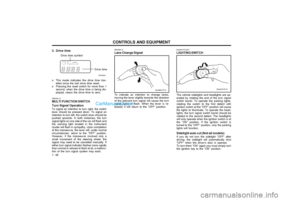
1- 38 The vehicle sidelights and headlights are op- erated by rotating the end of the turn signalswitch barrel. To operate the parking lights,rotating the switch to the first detent withignition switch at the "OFF" position will causethe lights to illuminate. To operate the head-lights, the turn signal switch barrel should berotated to the second detent. The headlightswill only operate when the ignition switch is atthe "ON" position. If the ignition switch isturned to the "OFF" position, only the parkinglights will function. Sidelight auto cut (Not all models) If you do not turn the sidelight "OFF" after driving, the sidelight will automatically shut"OFF" when the driver's door is opened. To turn them "ON" again you must simply turn the ignition key to the "ON" position.
B340C01FC-EAT
LIGHTING SWITCH
SB220A1-E MULTI FUNCTION SWITCH Turn Signal Operation To signal an intention to turn right, the switch lever should be pressed down. To signal anintention to turn left, the switch lever should bepushed upwards. In both instances, the turnsignal lights on one side of the car will flash andthe warning light located in the instrumentcluster will flash in sympathy. Upon completionof the manoeuvre, the lever will, under normal
circumstances, return to the "OFF" position.However, if the manoeuvre involved only asmall movement of the steering wheel, thesignal may need to be cancelled manually. Ifeither turn signal indicator flashes more rapidlythan normal or refuses to flash at all, a malfunc-tion of the turn signal system may exist. SB220B1-E Lane Change Signal To indicate an intention to change lanes, moving the lever slightly towards the directionof the relevant turn signal will cause the turnsignal lights to flash. When the lever is re-leased, it will return to the "OFF" position.
3. Drive time
Drive time symbol
Drive timeHFC2054
o This mode indicates the drive time trav- elled since the last drive time reset.
o Pressing the reset switch for more than 1 second, when the drive time is being dis- played, clears the drive time to zero. B340C01FC-D
B340B01FC-D