clock Hyundai Matrix 2005 Owner's Manual
[x] Cancel search | Manufacturer: HYUNDAI, Model Year: 2005, Model line: Matrix, Model: Hyundai Matrix 2005Pages: 407, PDF Size: 10.31 MB
Page 35 of 407
1- 27
CONTROLS AND EQUIPMENT
YT10355A
WARNING:
o Extreme Hazard! Do not use a rearwardfacing child restraint on a seat pro- tected by an airbag in front of it!
o Do not install a child restraint system in the front passenger seat position.
A child restraint system must never beplaced in the front seat. The infant orchild could be severely injured by anairbag deployment in case of an accident.
o Modification to SRS components or wiring, including the addition of anykind of badges to the pad covers ormodifications to the body structure,can adversely affect SRS performanceand lead to possible injury.
WARNING:
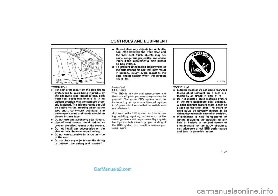
o For best protection from the side airbag
system and to avoid being injured is by the deploying side impact airbag, both front seat occupants should sit in an upright position with the seat belt prop-erly fastened. The driver's hands shouldbe placed on the steering wheel at the9:00 and 3:00 o'clock positions. Thepassenger's arms and hands should beplaced in their laps.
o Do not use any accessory seat covers.
o Use of seat covers could reduce or prevent the effectiveness of the system.
o Do not install any accessories on the side or near the side impact airbag.
o Do not use excessive force on the side of the seat.
o Do not place any objects over the airbag or between the airbag and yourself. B240C03Y-GAT SRS Care The SRS is virtually maintenance-free and there are no parts you can safely service byyourself. The entire SRS system must beinspected by an Hyundai authorised repairerin 10 years after the date that the vehicle wasmanufactured. Any work on the SRS system, such as remov- ing, installing, repairing, or any work on thesteering wheel must be performed by a quali-fied Hyundai technician. Improper handling ofthe SRS system may result in serious per-sonal injury.
HFC2092-DSide airbag sensor
o Do not place any objects (an umbrella,
bag, etc.) between the front door and the front seat. Such objects may be-come dangerous projectiles and causeinjury if the supplemental side impactair bag inflates.
o To prevent unexpected deployment of the side impact air bag that may resultin personal injury, avoid impact to theside airbag sensor when the ignitionkey is on.
Page 38 of 407
CONTROLS AND EQUIPMENT
1- 30
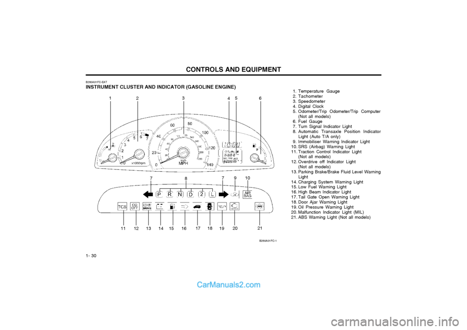
B260A01FC-EAT
INSTRUMENT CLUSTER AND INDICATOR (GASOLINE ENGINE) 1. Temperature Gauge
2. Tachometer
3. Speedometer
4. Digital Clock
5. Odometer/Trip Odometer/Trip Computer
(Not all models)
6. Fuel Gauge
7. Turn Signal Indicator Light
8. Automatic Transaxle Position Indicator Light (Auto T/A only)
9. Immobiliser Warning Indicator Light
10. SRS (Airbag) Warning Light
11. Traction Control Indicator Light (Not all models)
12. Overdrive off Indicator Light (Not all models)
13. Parking Brake/Brake Fluid Level Warning Light
14. Charging System Warning Light
15. Low Fuel Warning Light
16. High Beam Indicator Light
17. Tail Gate Open Warning Light
18. Door Ajar Warning Light
19. Oil Pressure Warning Light
20. Malfunction Indicator Light (MIL)
21. ABS Warning Light (Not all models)
B260A01FC-1
1
2 3
45
6
7 8 910
11 12 13 14 15 16 17 18
1920 21
7
Page 39 of 407
1- 31
CONTROLS AND EQUIPMENT
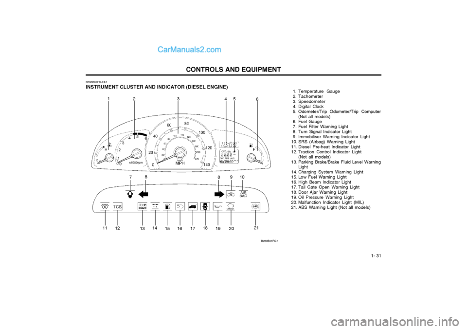
B260B01FC-EAT
INSTRUMENT CLUSTER AND INDICATOR (DIESEL ENGINE) 1. Temperature Gauge
2. Tachometer
3. Speedometer
4. Digital Clock
5. Odometer/Trip Odometer/Trip Computer
(Not all models)
6. Fuel Gauge
7. Fuel Filter Warning Light
8. Turn Signal Indicator Light
9. Immobiliser Warning Indicator Light
10. SRS (Airbag) Warning Light
11. Diesel Pre-heat Indicator Light
12. Traction Control Indicator Light
(Not all models)
13. Parking Brake/Brake Fluid Level Warning Light
14. Charging System Warning Light
15. Low Fuel Warning Light
16. High Beam Indicator Light
17. Tail Gate Open Warning Light
18. Door Ajar Warning Light
19. Oil Pressure Warning Light
20. Malfunction Indicator Light (MIL)
21. ABS Warning Light (Not all models)
B260B01FC-1
1 23 4 5
6
7 8
910
8
11 12
1314
15 16 17 18
19 20 21
Page 50 of 407
CONTROLS AND EQUIPMENT
1- 42 SB290A02-F CIGAR LIGHTER
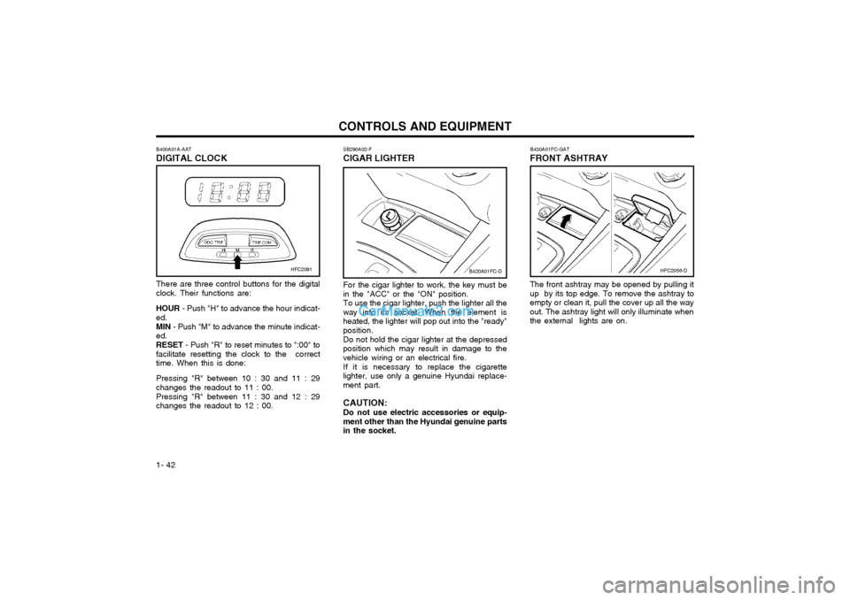
For the cigar lighter to work, the key must be
in the "ACC" or the "ON" position. To use the cigar lighter, push the lighter all the
way into its socket. When the element is heated, the lighter will pop out into the "ready"position.
Do not hold the cigar lighter at the depressed
position which may result in damage to thevehicle wiring or an electrical fire.
If it is necessary to replace the cigarette
lighter, use only a genuine Hyundai replace-ment part. CAUTION:
Do not use electric accessories or equip-
ment other than the Hyundai genuine parts in the socket. The front ashtray may be opened by pulling itup by its top edge. To remove the ashtray toempty or clean it, pull the cover up all the wayout. The ashtray light will only illuminate whenthe external lights are on.B430A01FC-GAT
FRONT ASHTRAY
There are three control buttons for the digitalclock. Their functions are: HOUR - Push "H" to advance the hour indicat-
ed. MIN - Push "M" to advance the minute indicat-
ed.RESET - Push "R" to reset minutes to ":00" to
facilitate resetting the clock to the correct time. When this is done: Pressing "R" between 10 : 30 and 11 : 29 changes the readout to 11 : 00. Pressing "R" between 11 : 30 and 12 : 29 changes the readout to 12 : 00.
B400A01A-AAT DIGITAL CLOCK
B420A01FC-DHFC2091HFC2056-D
Page 53 of 407

1- 45
CONTROLS AND EQUIPMENT
SB330C1-E Tilting the Sunroof SystemThe sunroof can be tilted and closed by de- pressing the button indicated. Release thebutton when the sunroof reaches the up posi-tion. NOTE: The sunroof should not be opened when water or standing rain is on the roof panel.Driving the vehicle for a short distance willallow the water to disperse naturally atwhich point the sunroof may be opened.
2. Turn the hexagonal bolts with a socketwrench counterclockwise to remove thefront overhead console.
3. Insert the hexagonal head wrench pro- vided with the vehicle into the socket. Thiswrench can be found in the vehicle's lug-gage room or glove box.
B460D01FC-EAT Manual Operation of Sunroof
HFC1036
If the sunroof fails to operate:
1. Remove the rectangular plastic interior light lenses in the front overhead console.
HFC1037
4. Turn the wrench clockwise to open or counterclockwise to close.
CAUTION:
o Do not open the sunroof in severe cold
temperature or when it is covered with ice or snow.
o Periodically remove any dirt that may have accumulated on the guide rails.
WARNING:
o Ensure that the sunroof and guide rails are clear of obstructions before closing the sunroof and ensure that nothingmay become entrapped between thesunroof panel and the vehicle bodywhilst the sunroof is being closed.
o Do not stand up or extend any portion of your body out of the opening whilstthe vehicle is moving.
HFC2022HFC1038
Page 72 of 407

CONTROLS AND EQUIPMENT
1- 64
B870D01FC-GAT ANTENNA Roof Antenna
Your car uses a roof antenna to receive both AM and FM broadcast signals. This antenna is a removable type. To remove the antenna, turn the antenna counterclock-wise. To install the antenna, turn the antennaclockwise. CAUTION:
o Be sure to remove the antenna before
washing the car in an automatic car wash or it may be damaged.
o Before entering a place with a low height clearance, be sure to adjust the roofantenna low.
o When reinstalling your antenna, it is important that it is fully tightened toensure proper reception.
HFC2100
Page 78 of 407

DRIVING YOUR HYUNDAI
2- 6 The shift points as shown above are recom- mended for optimum fuel economy and per- formance.
SC100A1-F
RECOMMENDED SHIFT POINTS
Shift
from-to
1-2 2-33-4 4-5 Recommended
mph (km/h)
15 (20) 25 (40) 35 (55) 45 (75)
C090A01FC-D
C090A01A-GAT AUTOMATIC TRANSAXLE The highly efficient Hyundai automatic transaxle has four forward speeds and one reverse speed. It has a conventional shift pattern as shown in the illustration. At night, with the first position of the multi-function switch, the appropriate symbol on the shift pattern indicator will be illuminated according to the range selected. CAUTION: Never shift into "R" or "P" position whilstthe vehicle is moving. NOTE:
Depress the brake pedal and push the button when shifting. Push the button when shifting.The selector lever can be shifted free- ly.SC090D1-F To Remove the Ignition Key
1. Turn the ignition key to the "ACC" position.
2. Simultaneously push and turn the ignitionkey counterclockwise from the "ACC" posi- tion to the "LOCK" position.
3. The key can be removed in the "LOCK"
position.
C070C01E
LOCK
ACC
ON
START
SC090B1-F Using the ClutchThe clutch should be pressed all the way to the floor before shifting, then released slowly. Do not rest your foot on the clutch pedal whilst driving. This can cause unnecessary wear.Do not partially engage the clutch to hold the car on an incline. This causes unnecessary wear.Use the parking brake to hold the car on an incline. Do not operate the clutch pedal rapidly and repeatedly.
Page 91 of 407
IN CASE OF EMERGENCY
3-4
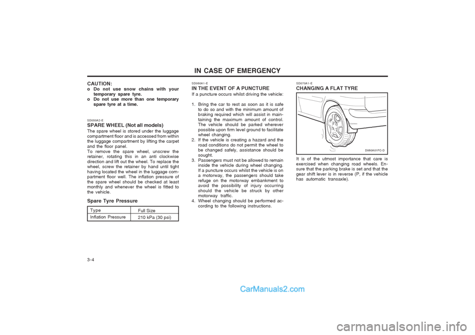
SD070A1-E
CHANGING A FLAT TYRE
It is of the utmost importance that care is
exercised when changing road wheels. En- sure that the parking brake is set and that the gear shift lever is in reverse (P, if the vehicle has automatic transaxle).
D060A01FC-D
SD050A2-E SPARE WHEEL (Not all models) The spare wheel is stored under the luggage compartment floor and is accessed from within the luggage compartment by lifting the carpet and the floor panel.To remove the spare wheel, unscrew the retainer, rotating this in an anti clockwise direction and lift out the wheel. To replace the wheel, screw the retainer by hand until tight having located the wheel in the luggage com- partment floor well. The inflation pressure of the spare wheel should be checked at least monthly and whenever the wheel is fitted to the vehicle. Spare Tyre Pressure
CAUTION:
o Do not use snow chains with your
temporary spare tyre.
o Do not use more than one temporary
spare tyre at a time. SD060A1-E
IN THE EVENT OF A PUNCTURE If a puncture occurs whilst driving the vehicle:
1. Bring the car to rest as soon as it is safe to do so and with the minimum amount of braking required which will assist in main- taining the maximum amount of control. The vehicle should be parked wherever possible upon firm level ground to facilitate wheel changing.
2. If the vehicle is creating a hazard and the road conditions do not permit the wheel tobe changed safely, assistance should be sought.
3. Passengers must not be allowed to remain inside the vehicle during wheel changing.If a puncture occurs whilst the vehicle is on a motorway, the passengers should take refuge on the motorway embankment to avoid the possibility of injury occurring should the vehicle be struck by other motorway traffic.
4. Wheel changing should be performed ac- cording to the following instructions.
Type Inflation Pressure Full Size210 kPa (30 psi)
Page 93 of 407

IN CASE OF EMERGENCY
3-6 SD070G1-E
5. Raising the Car
After inserting a wrench bar into the wheel nut
wrench, install the wrench bar into the jack as shown in the drawing. To raise the vehicle, turn the wheel nut wrench clockwise. As the jack begins to raise the vehicle, double check that it is properly positioned and will not slip. If the jack is on soft ground or sand, it may be necessary to place a stout piece of timber under the base of the jack to prevent it from sinking.
Raise the car high enough so that the fully
inflated spare wheel can be installed.
WARNING: Do not get under the car when it is support-
ed by the jack! The jack is solely designedfor wheel changing and is not intended to support the vehicle for other purposes. The use of purpose designed supports is neces- sary whilst the vehicle is raised and the operator is required to get underneath.
HFC4022
Wrench bar
Wheel nut wrench
SD070E1-E 3. Loosen Wheel Nuts The wheel nuts should be loosened slightly before raising the car. To loosen the nuts, turn the wheel brace counterclockwise. Ensure that the wheel brace socket is seated properly on the nut and that it cannot slip. Do not remove the nuts at this stage. SD070F1-F
4. Put the Jack in Place
The base of the jack should be placed on firm,level ground. The jack should be positioned as shown in the drawing.
D060D01FC-DHFC4006
Page 94 of 407

3-7
IN CASE OF EMERGENCY
WARNING: It is important that the faces of the wheeland hub are clean prior to installing the wheel. The prescence of dirt or other mat- ter in the wheel or hub faces could result in the wheel nuts becoming loose whilst the vehicle is being driven. SD070I1-E
7. Re-install Wheel Nuts
Fit the wheel nuts onto the studs and tighten with the wheel brace.
SD070H1-E 6. Changing Wheels Using the wheel brace, remove the nuts and slide the wheel off the hub and wheel studs. Lie the wheel flat to prevent it from rolling. Ensure that the faces of the wheel and hub are clean. Position the spare wheel over the studs and slide it up to the hub.
STA3071H
D060H01FC-D
D060G01FC
SD070J1-E
8. Lower Vehicle and Tighten Nuts
Lower the car to the ground turning the wheel
nut wrench counterclockwise. When the ve- hicle is firmly on the ground, remove the jack and tighten the wheel nuts securely. At the first available opportunity, the wheel nut torque should be checked with a suitable torque wrench.
Wheel nut tightening torqueSteel wheel & aluminium alloy wheel: 90-110 Nm (65-80 lb.ft)
D060I01FC-D