clock Hyundai Matrix 2005 User Guide
[x] Cancel search | Manufacturer: HYUNDAI, Model Year: 2005, Model line: Matrix, Model: Hyundai Matrix 2005Pages: 407, PDF Size: 10.31 MB
Page 113 of 407
OWNER MAINTENANCE
6-6 ZG030E1-A
ENGINE OIL CONSUMPTION Function of engine oil
Engine oil has the primary function of lubricat- ing and cooling the inside of the engine.
Engine oil consumption It is normal that an engine should consumesome engine oil in the course of normaldriving. The cause of oil consumption in anormal engine are as follows;
o Engine oil is used to lubricate pistons, piston rings and cylinders. A thin film of oil is left on the cylinder wall when a piston moves downwards in thecylinder. High negative pressure generatedduring engine operation sucks some of theoil into the combustion chamber.This oil with some oil of the cylinder wall isburned by the high temperature combustiongases during the combustion process.
o The engine oil consumption is strongly effected by the viscosity and quality of oil,engine rpm and driving condition etc. More engine oil may be consumed under severe driving conditions such as highspeeds, frequent acceleration and decel-eration, compared to normal driving.
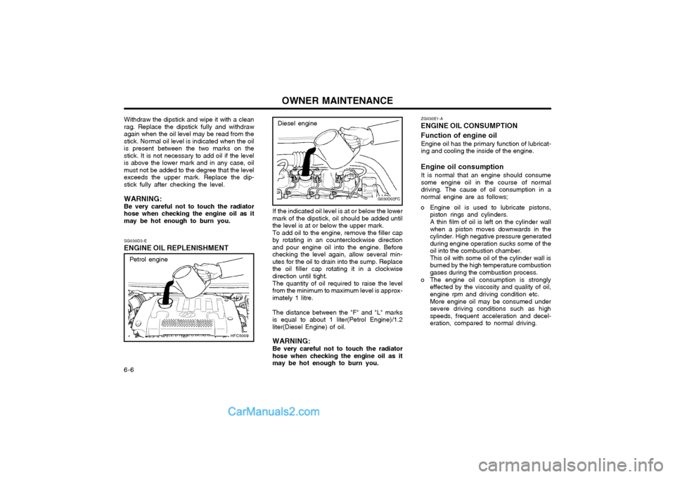
If the indicated oil level is at or below the lower
mark of the dipstick, oil should be added untilthe level is at or below the upper mark. To add oil to the engine, remove the filler cap
by rotating in an counterclockwise directionand pour engine oil into the engine. Beforechecking the level again, allow several min-utes for the oil to drain into the sump. Replacethe oil filler cap rotating it in a clockwisedirection until tight.
The quantity of oil required to raise the level
from the minimum to maximum level is approx-imately 1 litre.
The distance between the "F" and "L" marks
is equal to about 1 liter(Petrol Engine)/1.2liter(Diesel Engine) of oil.
WARNING: Be very careful not to touch the radiator
hose when checking the engine oil as it may be hot enough to burn you.
G030D02FC
Diesel engine
SG030D3-E
ENGINE OIL REPLENISHMENT
HFC5009
Petrol engine
Withdraw the dipstick and wipe it with a clean rag. Replace the dipstick fully and withdrawagain when the oil level may be read from thestick. Normal oil level is indicated when the oilis present between the two marks on thestick. It is not necessary to add oil if the levelis above the lower mark and in any case, oilmust not be added to the degree that the levelexceeds the upper mark. Replace the dip-stick fully after checking the level. WARNING: Be very careful not to touch the radiator hose when checking the engine oil as itmay be hot enough to burn you.
Page 114 of 407
OWNER MAINTENANCE 6-7
SG040A2-E
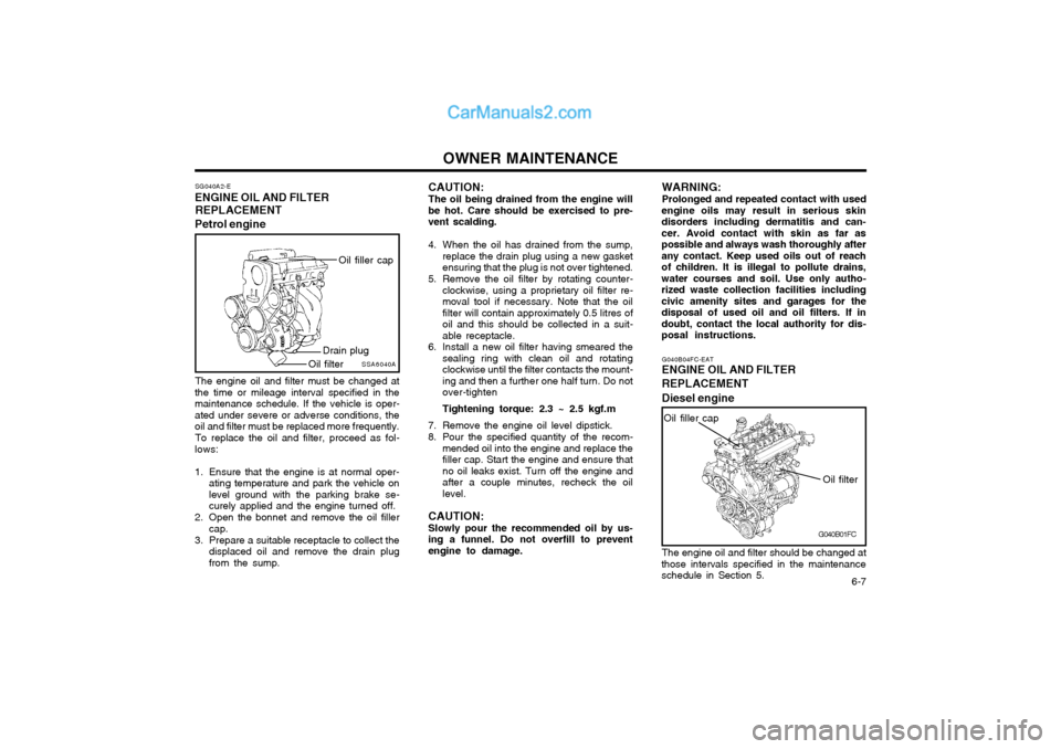
ENGINE OIL AND FILTER
REPLACEMENT
Petrol engine
SSA6040A
Oil filler cap
Drain plug
Oil filter
The engine oil and filter must be changed at
the time or mileage interval specified in the maintenance schedule. If the vehicle is oper-ated under severe or adverse conditions, theoil and filter must be replaced more frequently.
To replace the oil and filter, proceed as fol-
lows:
1. Ensure that the engine is at normal oper- ating temperature and park the vehicle on level ground with the parking brake se-curely applied and the engine turned off.
2. Open the bonnet and remove the oil filler cap.
3. Prepare a suitable receptacle to collect the displaced oil and remove the drain plugfrom the sump. CAUTION: The oil being drained from the engine will
be hot. Care should be exercised to pre- vent scalding.
4. When the oil has drained from the sump, replace the drain plug using a new gasket ensuring that the plug is not over tightened.
5. Remove the oil filter by rotating counter- clockwise, using a proprietary oil filter re-moval tool if necessary. Note that the oilfilter will contain approximately 0.5 litres ofoil and this should be collected in a suit-able receptacle.
6. Install a new oil filter having smeared the sealing ring with clean oil and rotatingclockwise until the filter contacts the mount-ing and then a further one half turn. Do notover-tighten Tightening torque: 2.3 ~ 2.5 kgf.m
7. Remove the engine oil level dipstick.
8. Pour the specified quantity of the recom- mended oil into the engine and replace the filler cap. Start the engine and ensure thatno oil leaks exist. Turn off the engine andafter a couple minutes, recheck the oillevel.
CAUTION: Slowly pour the recommended oil by us-
ing a funnel. Do not overfill to prevent engine to damage. WARNING: Prolonged and repeated contact with used
engine oils may result in serious skin disorders including dermatitis and can-cer. Avoid contact with skin as far aspossible and always wash thoroughly afterany contact. Keep used oils out of reachof children. It is illegal to pollute drains,water courses and soil. Use only autho-rized waste collection facilities includingcivic amenity sites and garages for thedisposal of used oil and oil filters. If indoubt, contact the local authority for dis-posal instructions.
G040B01FC
G040B04FC-EAT
ENGINE OIL AND FILTER REPLACEMENT Diesel engine
Oil filter
Oil filler cap
The engine oil and filter should be changed at
those intervals specified in the maintenance schedule in Section 5.
Page 115 of 407

OWNER MAINTENANCE
6-8 CAUTION: Slowly loosen the oil filter upper cap not to overflow the oil.
4. Remove the engine oil filler cap.
5. Slide underneath the car and loosen the oil pan drain plug by turning it counterclock- wise oil pan with a wrench of the propersize. Be sure that a drain pan is in positionto catch the oil as it drains out, then removethe drain plug.
WARNING: Be very careful when draining the engine oil as it may be hot enough to burn you!
6. When the oil has stopped draining, replace the drain plug using a new gasket andretighten by turning it clockwise. Oil pan drain plug tightening torque : 3.5 ~ 4.5 kgf.m
7. Pull out the oil filter upper cap with element from the oil filter housing.Using a clean cloth, remove any dirt or oil accumulated around the oil filter housing.
8. After mounting a new centrepipe O-ring, new oil filter element and new O-ring toupper cap, install the upper cap to oil filterhousing and retighten by turning it clock-wise. Do not over-tighten. Tightening torque : 2.5 kgf.m CAUTION: Don't use old oil filter upper cap O-ring
and centrepipe O-ring.
9. Refill the crankcase with the recommended engine oil. Refer to the specification in chapter 9 for engine oil capacity.
CAUTION: Slowly pour the recommended oil by us-
ing a funnel. Do not overfill not to damage the engine.
10.Start the engine and check to be sure no oil is leaking from the drain plug or oil filter.
11.Shut off the engine and recheck the oil level.
NOTE:
o It is recommended that the engine oil and filter should be changed by an Hyundai authorised repairer.
o Always dispose of used engine oil in an environmentally acceptable man-ner. It is suggested that it be placed ina sealed container and taken to a ser-vice station for maybe reclaimation.Do not pour the oil on the ground orput it into the household trash.
WARNING: Used motor oil may cause irritation or
cancer of the skin if left in contact with the skin for prolonged periods of time.Wash your hands thoroughly with soapand warm water as soon as possible afterhandling used oil.
Centrepipe O-ring
G040B02FC
O-ring
Oil filter housing
2. Open the bonnet and remove the engine oil level dipstick.
3. Loosen the oil filter upper cap with a proper tool from the oil filter housing until an O-ring is seen. Then, drain the oil completely.
Oil filter element
Upper cap
If the car is being driven in severe conditions,
more frequent oil and filter changes are re-quired.
The procedure for changing the oil and filter
is as follows:
1. Park the car on level ground and set the parking brake. Start the engine and let it warm up until the needle on the coolanttemperature gauge moves above the low-est mark. Turn the engine off and place thegear selector lever in "P" (automatic) orreverse gear (manual transaxle).
Page 118 of 407
OWNER MAINTENANCE 6-11
6. Start the engine with the radiator cap still
removed and continue to add coolant as the level decreases as air is expelled fromthe system. When the level remains con-stant, replace the radiator cap and replen-ish the coolant reservoir.
7. When the engine is hot, check to ensure that no coolant leaks are present.
WARNING: The cooling fan is controlled by engine coolant temperature and may sometimesoperate even when the engine is not run-ning. Use extreme caution when workingnear the blades of the cooling fan so thatyou are not injured by a rotating fanblade. As the engine coolant temperaturedecreases, the fan will automatically shutoff. This is a normal condition.
G050D02FCSSA6060B
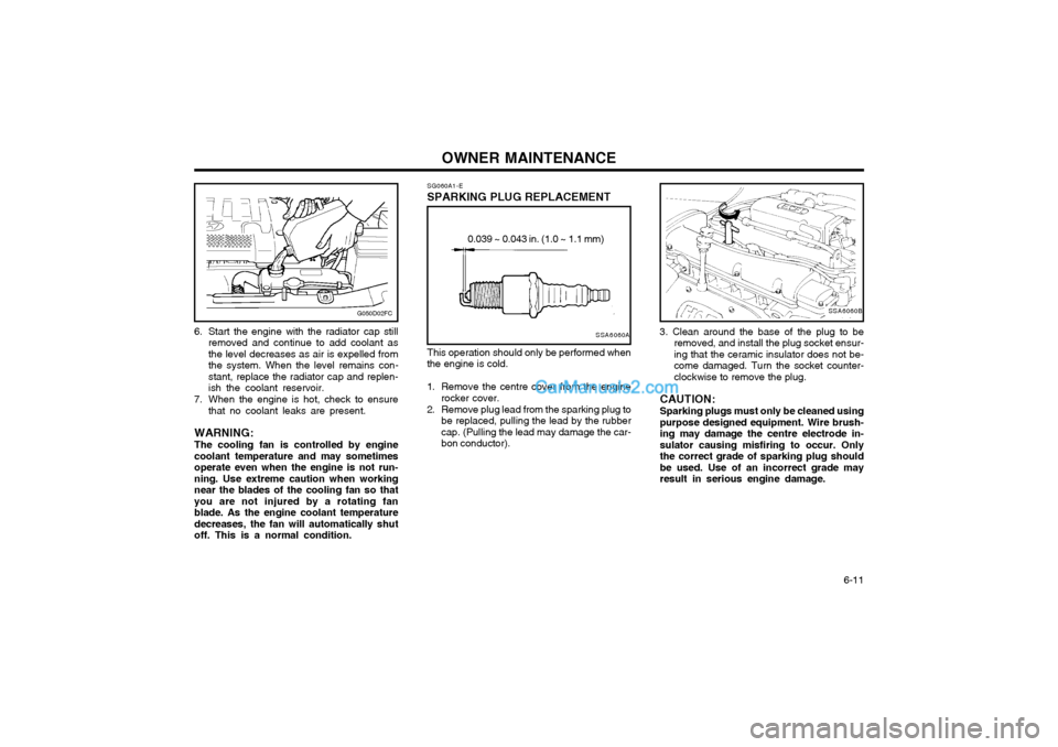
3. Clean around the base of the plug to be removed, and install the plug socket ensur- ing that the ceramic insulator does not be-come damaged. Turn the socket counter-clockwise to remove the plug.
CAUTION: Sparking plugs must only be cleaned using purpose designed equipment. Wire brush-ing may damage the centre electrode in-sulator causing misfiring to occur. Onlythe correct grade of sparking plug shouldbe used. Use of an incorrect grade mayresult in serious engine damage.
SG060A1-E
SPARKING PLUG REPLACEMENT
SSA6060A
0.039 ~ 0.043 in. (1.0 ~ 1.1 mm)
This operation should only be performed when
the engine is cold.
1. Remove the centre cover from the engine rocker cover.
2. Remove plug lead from the sparking plug to be replaced, pulling the lead by the rubber cap. (Pulling the lead may damage the car-bon conductor).
Page 147 of 407

INDEX10-1
A ACCESSORY TRAY
........................................................................ 1-50
AIR CONDITIONING SWITCH ........................................................ 1-60
AIR CONDITIONING SYSTEM MAINTENANCE ...........................6-18
AIR CLEANER ELEMENT REPLACEMENT ..................................6-12
ANTENNA ......................................................................................... 1-64
ANTI-THEFT ALARM SYSTEM .... .......................................... 1-5 ~ 1-7
AUTO FUEL CUT SWITCH ............................................................. 1-53
AUTOMATIC TRANSAXLE ............................................................... 2-6
AUTOMATIC TRANSAXLE FLUID ................................................ 6-14
B BATTERY MAINTENANCE ............................................................. 6-21
BEFORE STARTING THE ENGINE ................................................. 2-2
BLEEDING THE FUEL SYSTEM ....................................................6-23
BONNET RELEASE ......................................................................... 1-51
BRAKE PEDAL FREEPLAY .................................... ........................ 6-19
BRAKE TRACTION CONTROL SYSTEM ................... ................... 2-10
BRAKE SYSTEM CHECKING ........................................................ 6-16CCARE OF SEAT
BELTS ................................................................. 1-14
CARGO AREA COVER ................................................................... 1-53
CATALYTIC CONVERTOR OPERATING PRECAUTIONS ............. 7-1
CENTRE VENTILATOR ................................................................... 1-55
CENTRAL DOOR LOCKS ................................................................. 1-5
CHANGING A FLAT TYRE ............................................................... 3-4
CHECKING THE CLUTCH FLUID.................................................. 6-17
CHILD-PROOF REAR DOOR LOCK ................................................ 1-4
CHILD RESTRAINT SYSTEM ............................................. 1-17 ~ 1-22
CIGAR LIGHTER ............................................................................. 1-42
CLUTCH PEDAL FREEPLAY ......................................................... 6-19
COMBINATION IGNITION SWITCH AND STEERING LOCK ........ 2-2
COOLANT TEMPERATURE GAUGE .............................................1-35
D DAILY OPERATING CHECKS .......................................................... 6-4
DIGITAL CLOCK .............................................................................. 1-42
DOOR LOCKS ................................................................................... 1-3
DOOR WINDOWS ............................................................................. 1-7 DRINK HOLDER .............................................................................. 1-43
DRIVE BELTS .................................................................................. 6-20
DRIVING FOR ECONOMY ............................................................. 2-11
JK000A1-A 10. INDEX
10
Page 177 of 407

1
FEATURES OF YOUR HYUNDAI
13WINDOW
!
B050A01A-AAT WINDOW GLASS To raise or lower the window, turn the window regulator handle clockwise or counterclockwise.
WARNING:
When opening or closing the win-dows, make sure your passenger'sarms, hands and body are safely out of the way. B050A01FCB060A02E-AAT POWER WINDOWS (If Installed)
Close
The power windows operate when the ignition key is in the "ON" position. The main switches are located on thedriver's armrest and control the front and rear windows on both sides of the vehicle. The windows may be openedby depressing the appropriate window switch and closed by pulling up the switch. To open the window on thedriver's side, press the switch(1) down. The window moves as long as the switch is operated. B060A01FC
(1)
Open
In order to prevent operation of the passenger front and rear windows, awindow lock switch is provided on the armrest of the driver's door. To disable the power windows, press the windowlock switch. To return to normal operation, press the window lock switch a second time. HFC2013
Page 206 of 407
1FEATURES OF YOUR HYUNDAI
42
B240C03Y-GAT SRS Care The SRS is virtually maintenance-free and there are no parts you can safelyservice by yourself. The entire SRS system must be inspected by an au- thorized Hyundai dealer 10 years afterthe date that the vehicle was manufac- tured. Any work on the SRS system, such as removing, installing, repairing, or any work on the steering wheel must beperformed by a qualified Hyundai tech- nician. Improper handling of the SRS system may result in serious personalinjury.
!WARNING:
o The side impact airbag is supple- mental to the driver's and the passenger's seat belt systems and is not a substitute for them. Therefore your seat belts mustbe worn at all times while the vehicle is in motion. The airbags deploy only in certain side im-pact conditions severe enough to cause significant injury to the vehicle occupants.
o For best protection from the side
impact airbag system and toavoid being injured by the de- ploying side impact airbag, both front seat occupants should sitin an upright position with the seat belt properly fastened. The driver's hands should be placedon the steering wheel at the 9:00 and 3:00 o'clock positions. The passenger's arms and handsshould be placed on their laps.
o Do not use any accessory seat
covers. o Use of seat covers could reduce
or prevent the effectiveness ofthe system.
o Do not install any accessories on
the side or near the side impactairbag.
o Do not use excessive force on
the side of the seat.
o Do not place any objects over the airbag or between the airbag andyourself.
o Do not place any objects (an umbrella, bag, etc.) between thefront door and the front seat.Such objects may become dan- gerous projectiles and cause in- jury if the supplemental side im-pact air bag inflates.
o To prevent unexpected deploy-
ment of the side impact air bagthat may result in personal in- jury, avoid impact to the side airbag sensor when the ignitionkey is on.
Page 209 of 407
1
FEATURES OF YOUR HYUNDAI
45
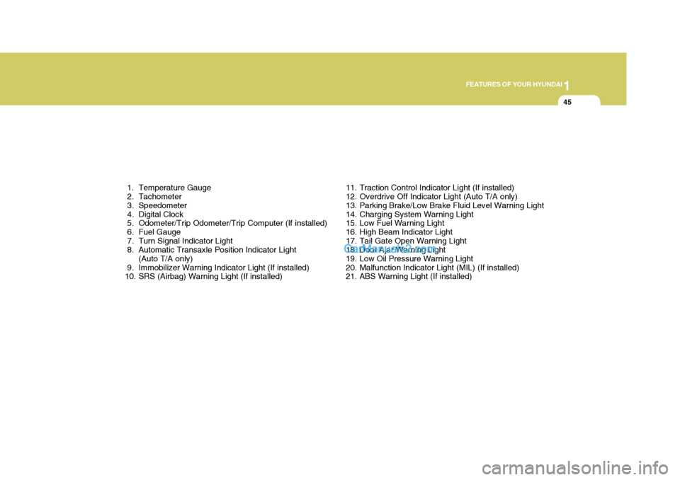
1. Temperature Gauge
2. Tachometer
3. Speedometer
4. Digital Clock
5. Odometer/Trip Odometer/Trip Computer (If installed)
6. Fuel Gauge
7. Turn Signal Indicator Light
8. Automatic Transaxle Position Indicator Light (Auto T/A only)
9. Immobilizer Warning Indicator Light (If installed)
10. SRS (Airbag) Warning Light (If installed) 11. Traction Control Indicator Light (If installed)
12. Overdrive Off Indicator Light (Auto T/A only)
13. Parking Brake/Low Brake Fluid Level Warning Light
14. Charging System Warning Light
15. Low Fuel Warning Light
16. High Beam Indicator Light
17. Tail Gate Open Warning Light
18. Door Ajar Warning Light
19. Low Oil Pressure Warning Light
20. Malfunction Indicator Light (MIL) (If installed)
21. ABS Warning Light (If installed)
Page 211 of 407
1
FEATURES OF YOUR HYUNDAI
47
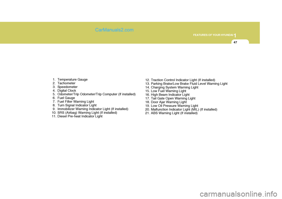
1. Temperature Gauge
2. Tachometer
3. Speedometer
4. Digital Clock
5. Odometer/Trip Odometer/Trip Computer (If installed)
6. Fuel Gauge
7. Fuel Filter Warning Light
8. Turn Signal Indicator Light
9. Immobilizer Warning Indicator Light (If installed)
10. SRS (Airbag) Warning Light (If installed)
11. Diesel Pre-heat Indicator Light 12. Traction Control Indicator Light (If installed)
13. Parking Brake/Low Brake Fluid Level Warning Light
14. Charging System Warning Light
15. Low Fuel Warning Light
16. High Beam Indicator Light
17. Tail Gate Open Warning Light
18. Door Ajar Warning Light
19. Low Oil Pressure Warning Light
20. Malfunction Indicator Light (MIL) (If installed)
21. ABS Warning Light (If installed)
Page 228 of 407
1FEATURES OF YOUR HYUNDAI
64CIGARETTE LIGHTER
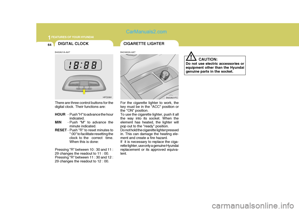
B420A02A-AAT For the cigarette lighter to work, the key must be in the "ACC" position or the "ON" position. To use the cigarette lighter, push it allthe way into its socket. When the element has heated, the lighter will pop out to the "ready" position.Do not hold the cigarette lighter pressed in. This can damage the heating ele- ment and create a fire hazard.If it is necessary to replace the ciga- rette lighter, use only a genuine Hyundai replacement or its approved equiva-lent. B420A01FC
CAUTION:
Do not use electric accessories orequipment other than the Hyundai genuine parts in the socket.
!
B400A01A-AAT
There are three control buttons for the digital clock. Their functions are: HOUR - Push "H" to advance the hour
indicated.
MIN - Push "M" to advance the
minute indicated.
RESET - Push "R" to reset minutes to
":00" to facilitate resetting the clock to the correct time.When this is done:
Pressing "R" between 10 : 30 and 11 :29 changes the readout to 11 : 00. Pressing "R" between 11 : 30 and 12 : 29 changes the readout to 12 : 00. DIGITAL CLOCK
HFC2091