fuse box Hyundai Matrix 2005 Owner's Manual
[x] Cancel search | Manufacturer: HYUNDAI, Model Year: 2005, Model line: Matrix, Model: Hyundai Matrix 2005Pages: 407, PDF Size: 10.31 MB
Page 55 of 407
1- 47
CONTROLS AND EQUIPMENT
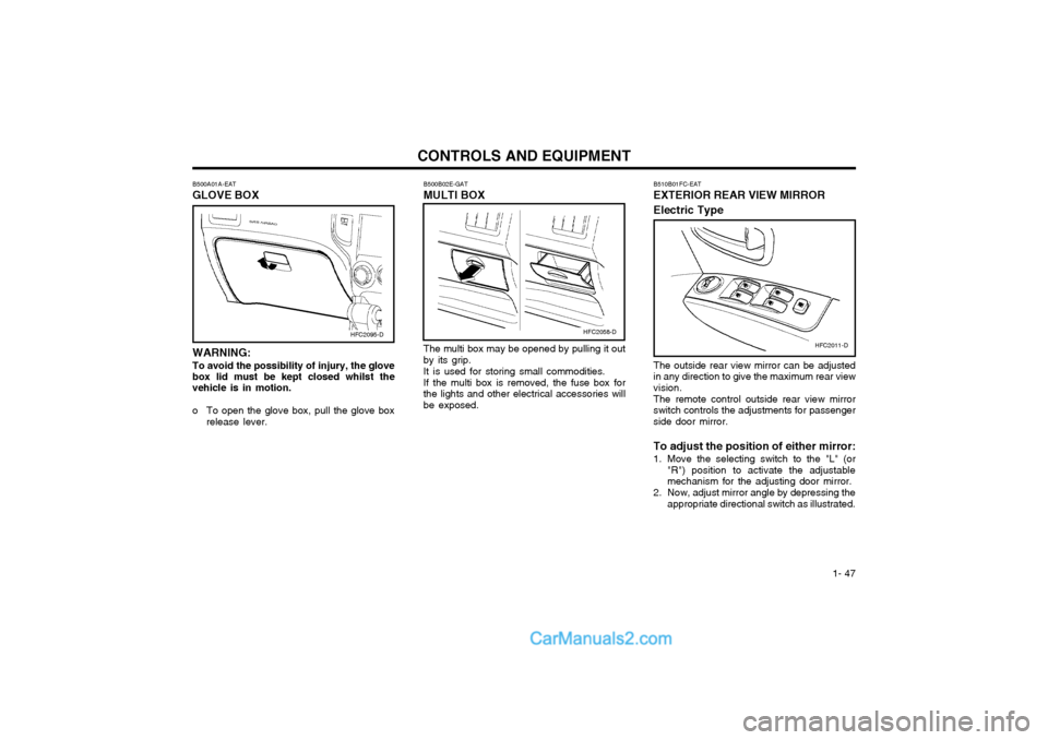
B500A01A-EAT GLOVE BOX WARNING: To avoid the possibility of injury, the glove box lid must be kept closed whilst the vehicle is in motion.
o To open the glove box, pull the glove box release lever. The multi box may be opened by pulling it out by its grip. It is used for storing small commodities.If the multi box is removed, the fuse box for the lights and other electrical accessories willbe exposed.
B500B02E-GAT MULTI BOX
HFC2095-DHFC2058-D
HFC2011-D
B510B01FC-EAT EXTERIOR REAR VIEW MIRROR Electric Type The outside rear view mirror can be adjusted in any direction to give the maximum rear viewvision. The remote control outside rear view mirror switch controls the adjustments for passengerside door mirror. To adjust the position of either mirror:
1. Move the selecting switch to the "L" (or
"R") position to activate the adjustable mechanism for the adjusting door mirror.
2. Now, adjust mirror angle by depressing the appropriate directional switch as illustrated.
Page 128 of 407
OWNER MAINTENANCE 6-21
G200B01E-EAT
INDIVIDUAL CIRCUIT FUSES
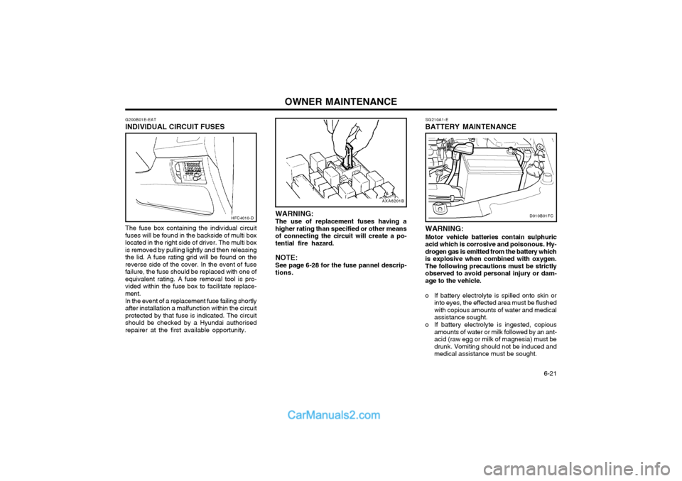
The fuse box containing the individual circuit fuses will be found in the backside of multi boxlocated in the right side of driver. The multi boxis removed by pulling lightly and then releasingthe lid. A fuse rating grid will be found on thereverse side of the cover. In the event of fusefailure, the fuse should be replaced with one ofequivalent rating. A fuse removal tool is pro-vided within the fuse box to facilitate replace-ment. In the event of a replacement fuse failing shortly after installation a malfunction within the circuitprotected by that fuse is indicated. The circuitshould be checked by a Hyundai authorisedrepairer at the first available opportunity.
HFC4010-D
AXA6201B
WARNING: The use of replacement fuses having a higher rating than specified or other meansof connecting the circuit will create a po-tential fire hazard. NOTE: See page 6-28 for the fuse pannel descrip- tions.
SG210A1-E
BATTERY MAINTENANCE
D010B01FC
WARNING:
Motor vehicle batteries contain sulphuric
acid which is corrosive and poisonous. Hy- drogen gas is emitted from the battery whichis explosive when combined with oxygen.The following precautions must be strictlyobserved to avoid personal injury or dam-age to the vehicle.
o If battery electrolyte is spilled onto skin or
into eyes, the effected area must be flushed with copious amounts of water and medicalassistance sought.
o If battery electrolyte is ingested, copious amounts of water or milk followed by an ant-acid (raw egg or milk of magnesia) must bedrunk. Vomiting should not be induced andmedical assistance must be sought.
Page 135 of 407
OWNER MAINTENANCE
6-28
G200C01FC-EAT
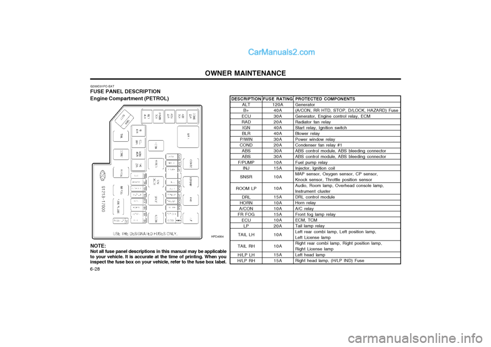
FUSE PANEL DESCRIPTION Engine Compartment (PETROL)
HFC4004PROTECTED COMPONENTS Generator (A/CON, RR HTD, STOP, D/LOCK, HAZARD) Fuse Generator, Engine control relay, ECM Radiator fan relay Start relay, Ignition switch Blower relay Power window relay Condenser fan relay #1 ABS control module, ABS bleeding connector ABS control module, ABS bleeding connector Fuel pump relay Injector, lgnition coil MAP sensor, Oxygen sensor, CP sensor, Knock sensor, Throttle position sensor Audio, Room lamp, Overhead console lamp, lnstrument cluster DRL control module Horn relay A/C relay Front fog lamp relay ECM, TCM Tail lamp relay Left rear combi lamp, Left position lamp, Left License lamp Right rear combi lamp, Right position lamp, Right License lamp Left head lamp Right head lamp, (H/LP IND) Fuse
FUSE RATING
120A40A 30A 20A 40A 40A 30A 20A 30A 30A 10A 15A 10A 10A 15A 10A 10A 15A 10A 20A 10A 10A 15A 15A
DESCRIPTION
ALTB+
ECU RAD IGN
BLR
P/WIN
COND
ABSABS
F/PUMP INJ
SNSR
ROOM LP DRL
HORN
A/CON
FR FOG
ECULP
TAIL LH
TAIL RH H/LP LH
H/LP RH
NOTE: Not all fuse panel descriptions in this manual may be applicable
to your vehicle. It is accurate at the time of printing. When you inspect the fuse box on your vehicle, refer to the fuse box label.
Page 136 of 407
OWNER MAINTENANCE 6-29
G200E02FC
G200E02FC-GAT
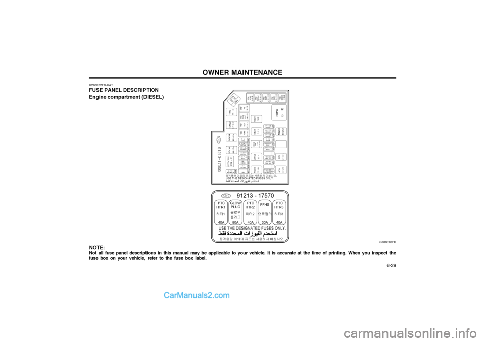
FUSE PANEL DESCRIPTION Engine compartment (DIESEL)
NOTE:
Not all fuse panel descriptions in this manual may be applicable to your vehicle. It is accurate at the time of printing. When you inspect the
fuse box on your vehicle, refer to the fuse box label.
Page 148 of 407
INDEX
10-2
E EFFECTIVE BRAKING
...................................................................... 2-9
ELECTRIC COOLING FANS ........................................................... 6-22
EMERGENCY TOWING ................... ...............................................3-10
EMISSION CONTROL SYSTEM ...................................................... 7-1
ENGINE COMPARTMENT ...................................................... 6-1 ~ 6-3
ENGINE COOLANT CHECKING AND REPLACING ....................... 6-9
ENGINE OIL AND FILTER REPLACEMENT ................................... 6-6
ENGINE OIL CONSUMPTION .......................................................... 6-6
ENGINE OIL REPLENISHMENT ...................................................... 6-5
ENGINE OIL ....................................................................................... 6-4
EXTERIOR REAR VIEW MIRR OR ................................................. 1-47
FFOLDING REAR SEATBACK AND SEAT CUSHION .......1-11 ~ 1-12
FOLD-UP TRAY ............................................................................... 1-50
FRONT ASHTRAY ........................................................................... 1-42
FRONT FOG LIGHT SWITCH ........................................................ 1-41
FUEL ECONOMY .............................................................................. 2-4
FUEL GAUGE .................................................................................. 1-35
FUEL RECOMMENDATIONS ........................................................... 1-1
FUSE PANEL DESCRIPTION ......................................................... 6-28
FUSIBLE LINKS ............................................................................... 6-20G GLOVE BOX
.................................................................................... 1-47
H HAZARD WARNING SYSTEM ........................................................ 1-40
HEADLIGHT AIMING ADJUSTEMENT ..........................................6-25
HEADLIGHT BULB ......................................................................... 6-24
HEADLIGHT LEVELING DEVICE SYSTEM ..................................1-44
HEAD RESTRAINT ADJUSTMENT ........................................ 1-9, 1-11
HEATED REAR WINDOW .............................................................. 1-41
HEATING CONTROL ....................................................................... 1-58
HEIGHT ADJUSTABLE FRONT SEAT SHOULDER BELT .......... 1-14
HORN ............................................................................................... 1-54
I
IF THE ENGINE CANNOT BE CRANKED ...................................... 3-1
IF THE ENGINE WILL NOT START ................................................ 3-1
IF THE EVENT OF A PUNCTURE ................................................... 3-4
IF YOUR VEHICLE MUST BE TOWED ........................................... 3-8
IMMOBILISER SYSTEM ......................................................... 1-2 ~ 1-3
INDIVIDUAL CIRCUIT FUSES ........................................................ 6-21
INSTRUMENT CLUSTER AND INDICATORS .............................. 1-30
INSTRUMENTS AND CONTROLS .................................................1-29
INTERIOR LIGHT ............................................................................ 1-46
INTERIOR REAR VIEW MIRROR .................................................. 1-49
Page 235 of 407
1
FEATURES OF YOUR HYUNDAI
71ACCESSORY TRAY
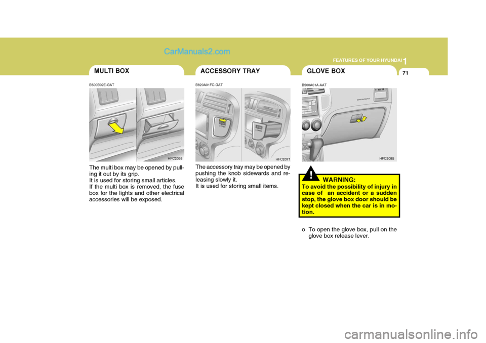
B820A01FC-GAT The accessory tray may be opened by pushing the knob sidewards and re- leasing slowly it.It is used for storing small items. HFC2071
!
GLOVE BOX
B500A01A-AAT
WARNING:
To avoid the possibility of injury in case of an accident or a sudden stop, the glove box door should bekept closed when the car is in mo- tion.
o To open the glove box, pull on the glove box release lever. HFC2095MULTI BOX
B500B02E-GAT The multi box may be opened by pull- ing it out by its grip.It is used for storing small articles. If the multi box is removed, the fuse box for the lights and other electricalaccessories will be exposed. HFC2058
Page 374 of 407
6
DO-IT-YOURSELF MAINTENANCE
29CHECKING AND REPLACING FUSES
G200A01A-AAT
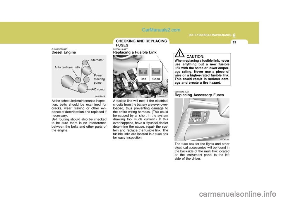
Replacing a Fusible Link
A fusible link will melt if the electrical
circuits from the battery are ever over- loaded, thus preventing damage to the entire wiring harness. (This could be caused by a short in the systemdrawing too much current.) If this ever happens, have a Hyundai dealer determine the cause, repair the sys-tem and replace the fusible link. The fusible links are located in a fuse box for easy inspection. Good
Bad
G200B01E-AAT Replacing Accessory Fuses
HFC4010
CAUTION:
When replacing a fusible link, never use anything but a new fusible link with the same or lower amper- age rating. Never use a piece ofwire or a higher-rated fusible link. This could result in serious dam- age and create a fire hazard.
!
G200A01FC
G190B01A
Power steeringpump
A/C comp.
Auto tentioner fully
Alternator
G190B01TB-GAT
Diesel Engine
At the scheduled maintenance inspec-
tion, belts should be examined for cracks, wear, fraying or other evi- dence of deterioration and replaced if necessary.
Belt routing should also be checked
to be sure there is no interferencebetween the belts and other parts ofthe engine.
The fuse box for the lights and otherelectrical accessories will be found inthe backside of the multi box located on the instrument panel to the left side of the driver.
Page 375 of 407
6 DO-IT-YOURSELF MAINTENANCE
30
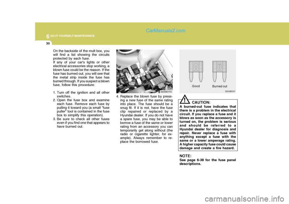
On the backside of the mult box, you will find a list showing the circuitsprotected by each fuse.If any of your car's lights or otherelectrical accessories stop working, ablown fuse could be the reason. If the fuse has burned out, you will see that the metal strip inside the fuse hasburned through. If you suspect a blown fuse, follow this procedure:
1. Turn off the ignition and all other switches.
2. Open the fuse box and examine
each fuse. Remove each fuse by pulling it toward you (a small "fuse puller" tool is contained in the fuse box to simplify this operation).
3. Be sure to check all other fuses even if you find one that appears tohave burned out. Good
G200B03Y
Burned out
CAUTION:
A burned-out fuse indicates that
there is a problem in the electrical circuit. If you replace a fuse and it blows as soon as the accessory isturned on, the problem is serious and should be referred to a Hyundai dealer for diagnosis andrepair. Never replace a fuse with anything except a fuse with the same or a lower amperage rating.A higher capacity fuse could cause damage and create a fire hazard.
NOTE: See page 6-38 for the fuse panel
descriptions.
!
G200B01FC
4. Replace the blown fuse by press- ing a new fuse of the same rating into place. The fuse should be a snug fit. If it is not, have the fuse clip repaired or replaced by a Hyundai dealer. If you do not havea spare fuse, you may be able to borrow a fuse of the same or lower rating from an accessory you cantemporarily get along without (the radio or cigarette lighter, for ex- ample). Always remember to re-place the borrowed fuse.
Page 384 of 407
6
DO-IT-YOURSELF MAINTENANCE
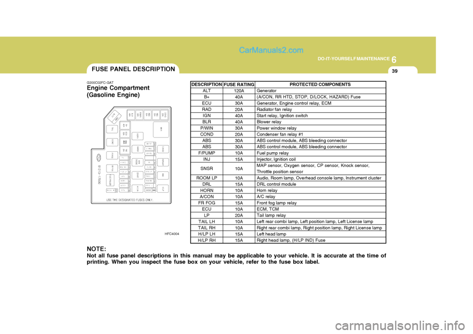
39FUSE PANEL DESCRIPTION
G200C02FC-GAT
Engine Compartment (Gasoline Engine)
HFC4004
NOTE: Not all fuse panel descriptions in this manual may be applicable to your vehicle. It is accurate at the time of printing. When you inspect the fuse box on your vehicle, refer to the fuse box label.
PROTECTED COMPONENTS
Generator (A/CON, RR HTD, STOP, D/LOCK, HAZARD) Fuse Generator, Engine control relay, ECM Radiator fan relay Start relay, Ignition switch Blower relay Power window relay Condenser fan relay #1 ABS control module, ABS bleeding connector ABS control module, ABS bleeding connector Fuel pump relay Injector, lgnition coil MAP sensor, Oxygen sensor, CP sensor, Knock sensor, Throttle position sensor Audio, Room lamp, Overhead console lamp, lnstrument cluster DRL control module Horn relay A/C relay Front fog lamp relay ECM, TCM Tail lamp relay Left rear combi lamp, Left position lamp, Left License lamp Right rear combi lamp, Right position lamp, Right License lamp Left head lamp Right head lamp, (H/LP IND) Fuse
FUSE RATING
120A
40A 30A 20A 40A 40A 30A 20A 30A 30A 10A 15A 10A10A 15A 10A 10A 15A 10A 20A 10A 10A 15A 15A
DESCRIPTION
ALTB+
ECU RAD IGN
BLR
P/WIN
COND
ABSABS
F/PUMP INJ
SNSR
ROOM LP DRL
HORN
A/CON
FR FOG ECU
LP
TAIL LH
TAIL RH H/LP LH
H/LP RH
Page 385 of 407
6 DO-IT-YOURSELF MAINTENANCE
40
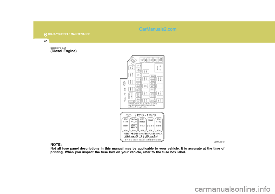
G200E02FC
G200E02FC-GAT
(Diesel Engine)
NOTE: Not all fuse panel descriptions in this manual may be applicable to your vehicle. It is accurate at the time of printing. When you inspect the fuse box on your vehicle, refer to the fuse box label.