headlight Hyundai Matrix 2005 Owner's Manual
[x] Cancel search | Manufacturer: HYUNDAI, Model Year: 2005, Model line: Matrix, Model: Hyundai Matrix 2005Pages: 407, PDF Size: 10.31 MB
Page 37 of 407
1- 29
CONTROLS AND EQUIPMENTHFC002-D
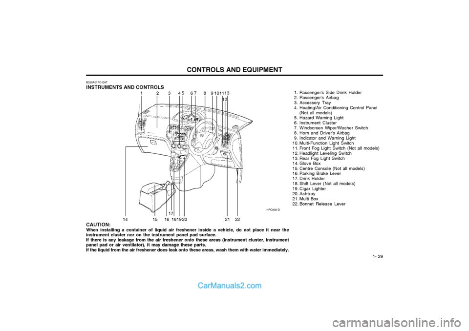
B250A01FC-EAT INSTRUMENTS AND CONTROLS
1. Passenger's Side Drink Holder
2. Passenger's Airbag
3. Accessory Tray
4. Heating/Air Conditioning Control Panel(Not all models)
5. Hazard Warning Light
6. Instrument Cluster
7. Windscreen Wiper/Washer Switch
8. Horn and Driver's Airbag
9. Indicator and Warning Light
10. Multi-Function Light Switch
11. Front Fog Light Switch (Not all models)
12. Headlight Leveling Switch
13. Rear Fog Light Switch
14. Glove Box
15. Centre Console (Not all models)
16. Parking Brake Lever
17. Drink Holder
18. Shift Lever (Not all models)
19. Cigar Lighter
20. Ashtray
21. Multi Box
22. Bonnet Release Lever
CAUTION: When installing a container of liquid air freshener inside a vehicle, do not place it near the instrument cluster nor on the instrument panel pad surface.If there is any leakage from the air freshener onto these areas (instrument cluster, instrumentpanel pad or air ventilator), it may damage these parts. If the liquid from the air freshener does leak onto these areas, wash them with water immediately. 1
2
34 5
67
89 1011
1213
14 15 1617
1819
20 2122
Page 40 of 407
CONTROLS AND EQUIPMENT
1- 32 SB210E1-E
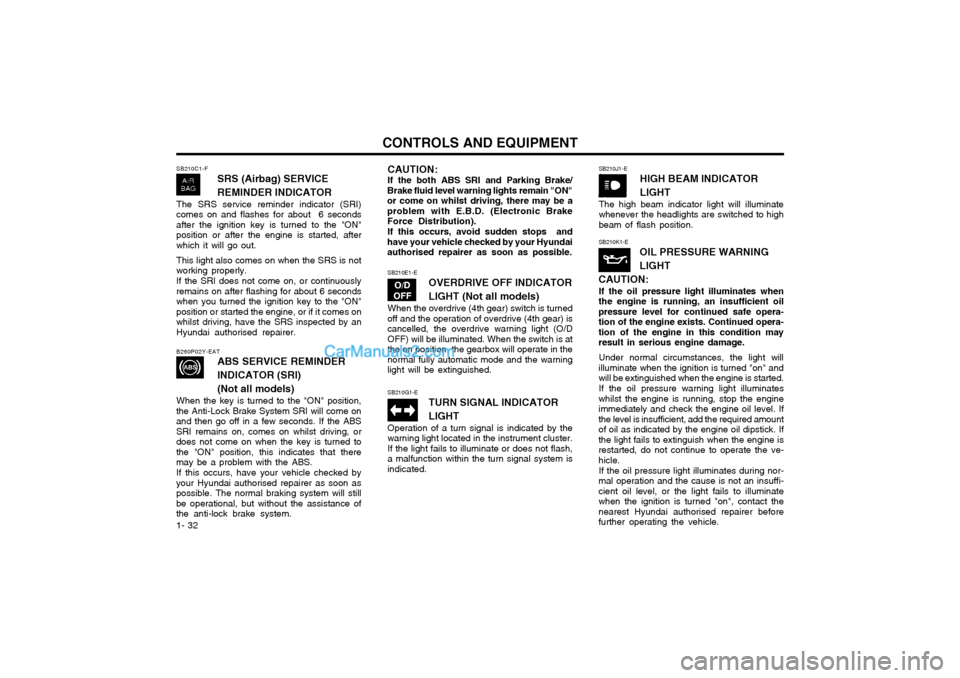
OVERDRIVE OFF INDICATOR LIGHT (Not all models)
When the overdrive (4th gear) switch is turned
off and the operation of overdrive (4th gear) is cancelled, the overdrive warning light (O/DOFF) will be illuminated. When the switch is atthe on position, the gearbox will operate in thenormal fully automatic mode and the warninglight will be extinguished.
B260P02Y-EAT
ABS SERVICE REMINDER INDICATOR (SRI)(Not all models)
When the key is turned to the "ON" position,
the Anti-Lock Brake System SRI will come on and then go off in a few seconds. If the ABSSRI remains on, comes on whilst driving, ordoes not come on when the key is turned tothe "ON" position, this indicates that theremay be a problem with the ABS.
If this occurs, have your vehicle checked by
your Hyundai authorised repairer as soon aspossible. The normal braking system will stillbe operational, but without the assistance ofthe anti-lock brake system.
CAUTION: If the both ABS SRI and Parking Brake/
Brake fluid level warning lights remain "ON" or come on whilst driving, there may be aproblem with E.B.D. (Electronic Brake
Force Distribution).
If this occurs, avoid sudden stops and
have your vehicle checked by your Hyundaiauthorised repairer as soon as possible. SB210K1-E
OIL PRESSURE WARNING LIGHT
CAUTION: If the oil pressure light illuminates when
the engine is running, an insufficient oil pressure level for continued safe opera-tion of the engine exists. Continued opera-tion of the engine in this condition mayresult in serious engine damage.
Under normal circumstances, the light will
illuminate when the ignition is turned "on" andwill be extinguished when the engine is started.
If the oil pressure warning light illuminates
whilst the engine is running, stop the engineimmediately and check the engine oil level. Ifthe level is insufficient, add the required amountof oil as indicated by the engine oil dipstick. Ifthe light fails to extinguish when the engine isrestarted, do not continue to operate the ve-hicle.
If the oil pressure light illuminates during nor-
mal operation and the cause is not an insuffi-cient oil level, or the light fails to illuminatewhen the ignition is turned "on", contact thenearest Hyundai authorised repairer beforefurther operating the vehicle.
SB210G1-E
TURN SIGNAL INDICATOR LIGHT
Operation of a turn signal is indicated by the
warning light located in the instrument cluster. If the light fails to illuminate or does not flash,a malfunction within the turn signal system isindicated.
SB210J1-E
HIGH BEAM INDICATOR LIGHT
The high beam indicator light will illuminate whenever the headlights are switched to highbeam of flash position.
SB210C1-F
SRS (Airbag) SERVICE REMINDER INDICATOR
The SRS service reminder indicator (SRI) comes on and flashes for about 6 secondsafter the ignition key is turned to the "ON"position or after the engine is started, afterwhich it will go out. This light also comes on when the SRS is not working properly. If the SRI does not come on, or continuously remains on after flashing for about 6 secondswhen you turned the ignition key to the "ON"position or started the engine, or if it comes onwhilst driving, have the SRS inspected by anHyundai authorised repairer.
Page 46 of 407
CONTROLS AND EQUIPMENT
1- 38 The vehicle sidelights and headlights are op- erated by rotating the end of the turn signalswitch barrel. To operate the parking lights,rotating the switch to the first detent withignition switch at the "OFF" position will causethe lights to illuminate. To operate the head-lights, the turn signal switch barrel should berotated to the second detent. The headlightswill only operate when the ignition switch is atthe "ON" position. If the ignition switch isturned to the "OFF" position, only the parkinglights will function. Sidelight auto cut (Not all models) If you do not turn the sidelight "OFF" after driving, the sidelight will automatically shut"OFF" when the driver's door is opened. To turn them "ON" again you must simply turn the ignition key to the "ON" position.
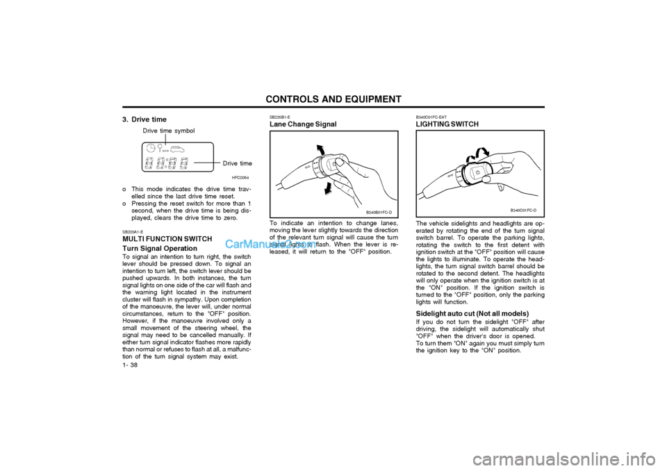
B340C01FC-EAT
LIGHTING SWITCH
SB220A1-E MULTI FUNCTION SWITCH Turn Signal Operation To signal an intention to turn right, the switch lever should be pressed down. To signal anintention to turn left, the switch lever should bepushed upwards. In both instances, the turnsignal lights on one side of the car will flash andthe warning light located in the instrumentcluster will flash in sympathy. Upon completionof the manoeuvre, the lever will, under normal
circumstances, return to the "OFF" position.However, if the manoeuvre involved only asmall movement of the steering wheel, thesignal may need to be cancelled manually. Ifeither turn signal indicator flashes more rapidlythan normal or refuses to flash at all, a malfunc-tion of the turn signal system may exist. SB220B1-E Lane Change Signal To indicate an intention to change lanes, moving the lever slightly towards the directionof the relevant turn signal will cause the turnsignal lights to flash. When the lever is re-leased, it will return to the "OFF" position.
3. Drive time
Drive time symbol
Drive timeHFC2054
o This mode indicates the drive time trav- elled since the last drive time reset.
o Pressing the reset switch for more than 1 second, when the drive time is being dis- played, clears the drive time to zero. B340C01FC-D
B340B01FC-D
Page 47 of 407
1- 39
CONTROLS AND EQUIPMENT
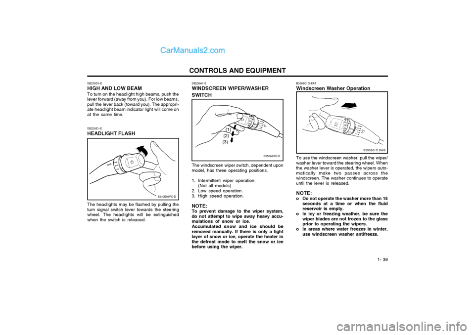
The windscreen wiper switch, dependent upon model, has three operating positions.
1. Intermittent wiper operation.(Not all models)
2. Low speed operation.
3. High speed operation. NOTE: To prevent damage to the wiper system,do not attempt to wipe away heavy accu-mulations of snow or ice. Accumulated snow and ice should be removed manually. If there is only a lightlayer of snow or ice, operate the heater inthe defrost mode to melt the snow or icebefore using the wiper.
SB230A1-E WINDSCREEN WIPER/WASHER SWITCH
SB220E1-E HEADLIGHT FLASH The headlights may be flashed by pulling the turn signal switch lever towards the steeringwheel. The headlights will be extinguishedwhen the switch is released.
SB220D1-E HIGH AND LOW BEAM To turn on the headlight high beams, push the lever forward (away from you). For low beams,pull the lever back (toward you). The appropri-ate headlight beam indicator light will come onat the same time.
B340E01FC-D
B350A01O-D
(1)
(2)
(3)
B350B01O-EAT Windscreen Washer Operation To use the windscreen washer, pull the wiper/ washer lever toward the steering wheel. Whenthe washer lever is operated, the wipers auto-matically make two passes across thewindscreen. The washer continues to operateuntil the lever is released. NOTE:
o Do not operate the washer more than 15 seconds at a time or when the fluid reservoir is empty.
o In icy or freezing weather, be sure the wiper blades are not frozen to the glassprior to operating the wipers.
o In areas where water freezes in winter, use windscreen washer antifreeze. B350B01O.DAG
Page 49 of 407
1- 41
CONTROLS AND EQUIPMENTNOTE: The engine must be running for the heated
rear window to operate.
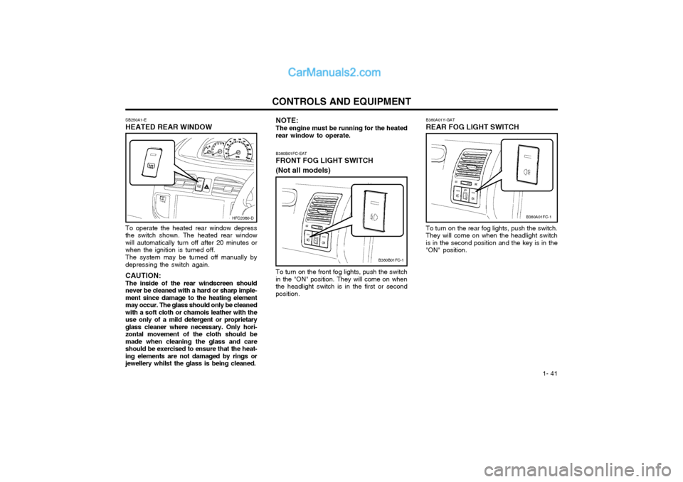
SB250A1-E HEATED REAR WINDOW To operate the heated rear window depress the switch shown. The heated rear windowwill automatically turn off after 20 minutes orwhen the ignition is turned off. The system may be turned off manually by depressing the switch again. CAUTION: The inside of the rear windscreen shouldnever be cleaned with a hard or sharp imple-ment since damage to the heating elementmay occur. The glass should only be cleanedwith a soft cloth or chamois leather with theuse only of a mild detergent or proprietaryglass cleaner where necessary. Only hori-zontal movement of the cloth should bemade when cleaning the glass and careshould be exercised to ensure that the heat-ing elements are not damaged by rings orjewellery whilst the glass is being cleaned. B360A01Y-GAT REAR FOG LIGHT SWITCH To turn on the rear fog lights, push the switch. They will come on when the headlight switchis in the second position and the key is in the"ON" position.
HFC2080-D
B360B01FC-1
B360B01FC-EAT
FRONT FOG LIGHT SWITCH (Not all models)
To turn on the front fog lights, push the switch
in the "ON" position. They will come on when the headlight switch is in the first or secondposition.
B360A01FC-1
Page 52 of 407
CONTROLS AND EQUIPMENT
1- 44 SB330A2-E
SUNROOF (Not all models)
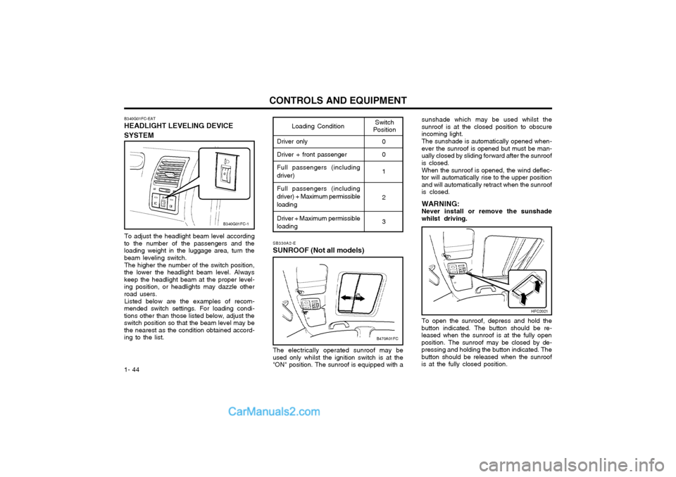
To adjust the headlight beam level according
to the number of the passengers and the loading weight in the luggage area, turn thebeam leveling switch.
The higher the number of the switch position,
the lower the headlight beam level. Alwayskeep the headlight beam at the proper level-ing position, or headlights may dazzle otherroad users.
Listed below are the examples of recom-
mended switch settings. For loading condi-tions other than those listed below, adjust theswitch position so that the beam level may bethe nearest as the condition obtained accord-ing to the list.
Switch
PositionLoading Condition
Driver only Driver + front passengerFull passengers (including
driver)
Full passengers (including
driver) + Maximum permissible loading
Driver + Maximum permissible
loading 0 0 1 2 3
B340G01FC-EAT HEADLIGHT LEVELING DEVICE SYSTEM
sunshade which may be used whilst the sunroof is at the closed position to obscureincoming light. The sunshade is automatically opened when- ever the sunroof is opened but must be man-ually closed by sliding forward after the sunroofis closed. When the sunroof is opened, the wind deflec- tor will automatically rise to the upper positionand will automatically retract when the sunroofis closed. WARNING: Never install or remove the sunshadewhilst driving. To open the sunroof, depress and hold the
button indicated. The button should be re- leased when the sunroof is at the fully openposition. The sunroof may be closed by de-pressing and holding the button indicated. Thebutton should be released when the sunroofis at the fully closed position.
HFC2021
B470A01FC
B340G01FC-1
The electrically operated sunroof may be used only whilst the ignition switch is at the"ON" position. The sunroof is equipped with a
Page 57 of 407
1- 49
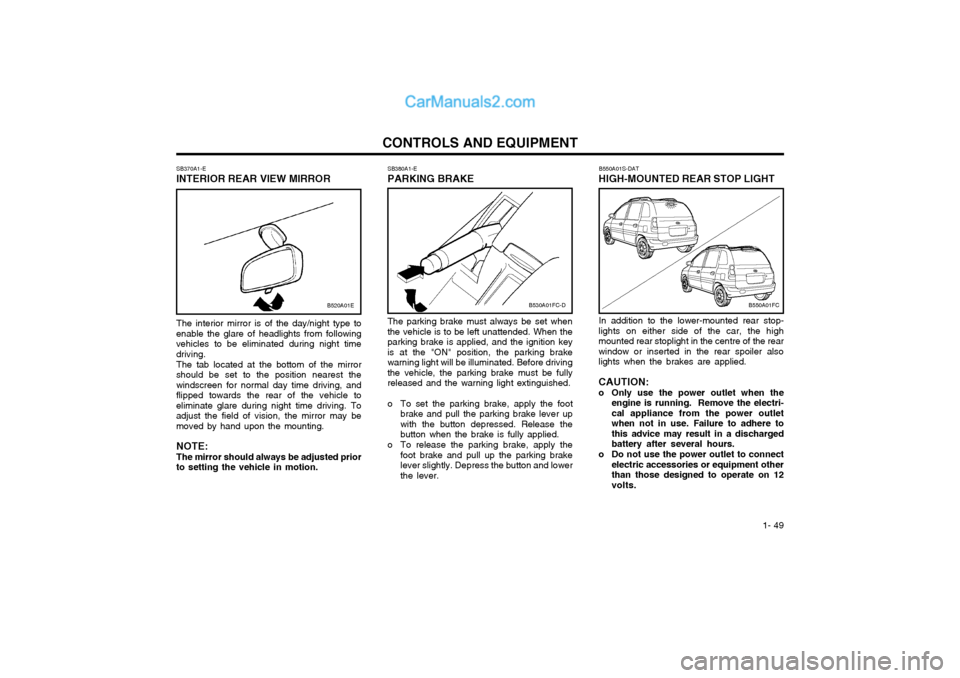
CONTROLS AND EQUIPMENTSB380A1-E PARKING BRAKE The parking brake must always be set when the vehicle is to be left unattended. When theparking brake is applied, and the ignition keyis at the "ON" position, the parking brakewarning light will be illuminated. Before drivingthe vehicle, the parking brake must be fullyreleased and the warning light extinguished.
o To set the parking brake, apply the foot brake and pull the parking brake lever up with the button depressed. Release thebutton when the brake is fully applied.
o To release the parking brake, apply the foot brake and pull up the parking brakelever slightly. Depress the button and lowerthe lever.
SB370A1-E
INTERIOR REAR VIEW MIRROR
The interior mirror is of the day/night type to
enable the glare of headlights from followingvehicles to be eliminated during night timedriving.
The tab located at the bottom of the mirror
should be set to the position nearest thewindscreen for normal day time driving, andflipped towards the rear of the vehicle toeliminate glare during night time driving. Toadjust the field of vision, the mirror may bemoved by hand upon the mounting.
NOTE:The mirror should always be adjusted prior
to setting the vehicle in motion.
B530A01FC-DB550A01FC
B520A01E
B550A01S-DAT
HIGH-MOUNTED REAR STOP LIGHT
In addition to the lower-mounted rear stop-
lights on either side of the car, the high
mounted rear stoplight in the centre of the rearwindow or inserted in the rear spoiler alsolights when the brakes are applied. CAUTION:
o Only use the power outlet when the engine is running. Remove the electri-cal appliance from the power outletwhen not in use. Failure to adhere tothis advice may result in a dischargedbattery after several hours.
o Do not use the power outlet to connect electric accessories or equipment otherthan those designed to operate on 12volts.
Page 131 of 407

OWNER MAINTENANCE
6-24 G270A02A-GAT HEADLIGHT BULB Replacement instructions:
G270A01FC
1. Allow the bulb to cool. Wear eye protection.
2. Always grasp the bulb by its plastic base, avoid touching the glass.
SG250A1-E
REPLACING LIGHT BULBS
In the event of bulb failure being experienced, ensure that the relative lighting circuit is turnedoff prior to attempting to replace the bulb. Theillustrations on the following page will assist inlocating and removing the various bulbs. En-sure that the replacement bulb has the samecap configuration and wattage as the original. CAUTION: Keep the lamps out of contact with petro- leum products, such as oil, petrol, etc.
1. Loosen the drain plug at the bottom of the
fuel filter.
2. Tighten the drain plug when water no longer comes out.
3. Check to be sure that the warning lamp illuminates when the ignition key is turnedto "ON", and that it goes off when theengine is started. If in doubt, consult your nearest Hyundai authorised repairer.
NOTE: It is recommended that water accumu- lated in the fuel filter should be removedby an authorized Hyundai authorised re-pairer. WARNING:
o Do not smoke or have any other open flame near the vehicle while bleeding the fuel system.
o Be sure to carefully wipe away any water drained out in this manner, be-cause the fuel mixed in the water mightbe ignited and result in a fire.
G300B02FC
If the fuel filter warning lamp illuminates during driving, it indicates that water has accumu-lated in the fuel filter. If this occurs, remove thewater as described.
G300A01B-GAT REMOVAL OF WATER FROM THE FUEL FILTER (Diesel engine)
G300A02FC
Page 132 of 407
OWNER MAINTENANCE 6-25
5. Push the bulb spring for removing the
headlight bulb.
6. Remove the protective cap from the re- placement bulb and install the new bulb by matching the plastic base with the headlighthole. Install the dust cover after retighteningthe bulb spring and reconnect the powercord.
7. Use the protective cap and carton to dis- pose of the old bulb.
8. Check for proper headlight aim.
WARNING The halogen bulb contains gas under
pressure and if impacted could shatter, resulting in flying fragments. Always weareye protection when servicing the bulb.
G270A02FC
3. Disconnect the power cord from the bulb base in the back of the headlight.
4. Remove the dust cover.
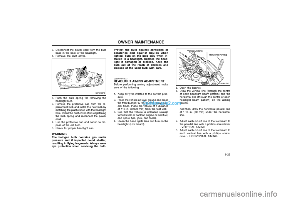
5. Open the bonnet.
6. Draw the vertical line (through the centreof each headlight beam pattern) and the horizontal line (through the centre of eachheadlight beam pattern) on the aimingscreen. And then, draw the horizontal parallel line at 1.18 in. (30 mm) under the horizontalline.
7. Adjust each cut-off line of the low beam to the parallel line with a phillips screwdriver- VERTICAL AIMING
8. Adjust each cut-off line of the low beam to each vertical line with a phillips screw-driver - HORIZONTAL AIMING.
G290A01FC-EAT
HEADLIGHT AIMING ADJUSTMENT
Before performing aiming adjustment, makesure of the following.
1. Keep all tyres inflated to the correct pres- sure.
2. Place the vehicle on level ground and press the front bumper & rear bumper down sev-eral times. Place the vehicle at a distanceof 118 in. (3,000 mm) from the test wall.
3. See that the vehicle is unloaded (except for full levels of coolant, engine oil and fuel,and spare tyre, jack, and tools).
4. Clean the head lights lens and turn on the headlight (Low beam).
G290A01FC
Horizontal Aiming
Vertical Aiming
Protect the bulb against abrasions or scratches and against liquids whenlighted. Turn on the bulb only when in-stalled in a headlight. Replace the head-light if damaged or cracked. Keep thebulb out of the reach of children anddispose of the used bulb with care.
Page 133 of 407
OWNER MAINTENANCE
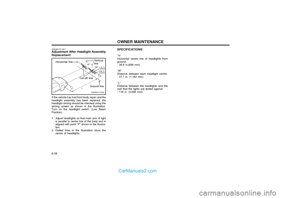
6-26 SPECIFICATIONS: "H" Horizontal centre line of headlights from ground. : 26.8 in.(656 mm) "W" Distance between each headlight centre.: 47.7 in. (1,164 mm) "L" Distance between the headlights and thewall that the lights are tested against. : 118 in. (3,000 mm).
G290B01FC-EAT
Adjustment After Headlight Assembly Replacement
Horizontal line
If the vehicle has had front body repair and the
headlight assembly has been replaced, the headlight aiming should be checked using theaiming screen as shown in the illustration.Turn on the headlight switch. (Low BeamPosition)
1. Adjust headlights so that main axis of light is parallel to centre line of the body and is aligned with point "P" shown in the illustra-tion.
2. Dotted lines in the illustration show the centre of headlights. G290B01S-DAGVertical line
W
0.59 in. (15mm)"P" 1.18 in. (30mm)
Cut-off line
Ground line H
H L