steering Hyundai Matrix 2005 Owner's Manual
[x] Cancel search | Manufacturer: HYUNDAI, Model Year: 2005, Model line: Matrix, Model: Hyundai Matrix 2005Pages: 407, PDF Size: 10.31 MB
Page 32 of 407
CONTROLS AND EQUIPMENT
1- 24
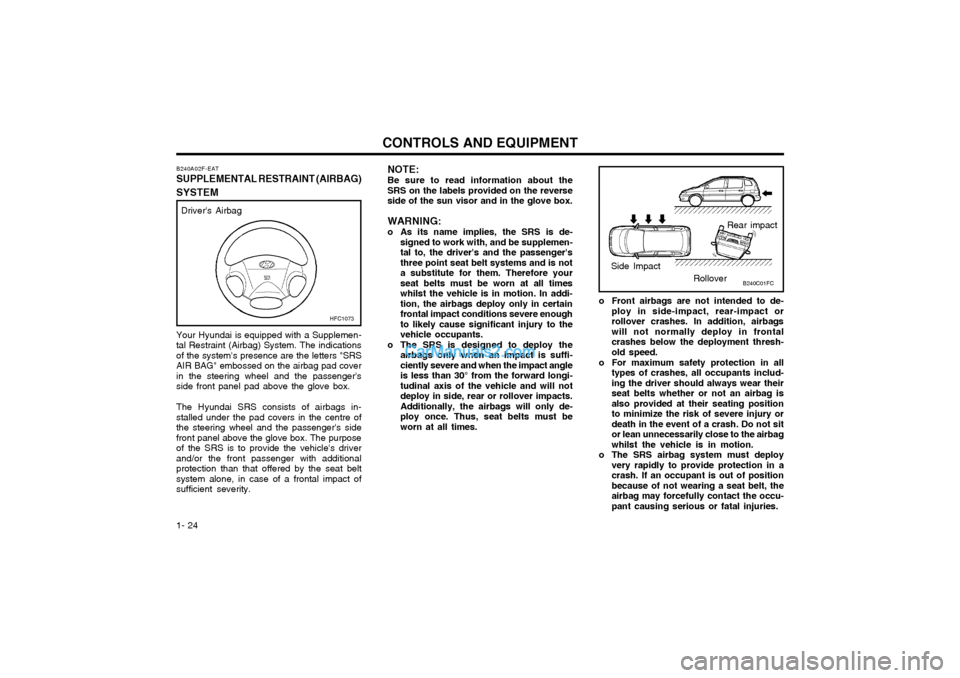
Your Hyundai is equipped with a Supplemen- tal Restraint (Airbag) System. The indicationsof the system's presence are the letters "SRSAIR BAG" embossed on the airbag pad coverin the steering wheel and the passenger'sside front panel pad above the glove box. The Hyundai SRS consists of airbags in- stalled under the pad covers in the centre ofthe steering wheel and the passenger's sidefront panel above the glove box. The purposeof the SRS is to provide the vehicle's driverand/or the front passenger with additionalprotection than that offered by the seat beltsystem alone, in case of a frontal impact ofsufficient severity. NOTE: Be sure to read information about the SRS on the labels provided on the reverseside of the sun visor and in the glove box. WARNING:
o As its name implies, the SRS is de-
signed to work with, and be supplemen- tal to, the driver's and the passenger'sthree point seat belt systems and is nota substitute for them. Therefore yourseat belts must be worn at all timeswhilst the vehicle is in motion. In addi-tion, the airbags deploy only in certainfrontal impact conditions severe enoughto likely cause significant injury to thevehicle occupants.
o The SRS is designed to deploy the airbags only when an impact is suffi-ciently severe and when the impact angleis less than 30° from the forward longi-tudinal axis of the vehicle and will notdeploy in side, rear or rollover impacts.Additionally, the airbags will only de-ploy once. Thus, seat belts must beworn at all times.
Driver's Airbag
B240A02F-EAT
SUPPLEMENTAL RESTRAINT (AIRBAG)
SYSTEM
HFC1073
Rear impact
Side Impact RolloverB240C01FC
o Front airbags are not intended to de-
ploy in side-impact, rear-impact or rollover crashes. In addition, airbagswill not normally deploy in frontalcrashes below the deployment thresh-old speed.
o For maximum safety protection in all types of crashes, all occupants includ-ing the driver should always wear theirseat belts whether or not an airbag isalso provided at their seating positionto minimize the risk of severe injury ordeath in the event of a crash. Do not sitor lean unnecessarily close to the airbagwhilst the vehicle is in motion.
o The SRS airbag system must deploy very rapidly to provide protection in acrash. If an occupant is out of positionbecause of not wearing a seat belt, theairbag may forcefully contact the occu-pant causing serious or fatal injuries.
Page 33 of 407
1- 25
CONTROLS AND EQUIPMENT
Passenger's Airbag
B240B04FC-D
Upon deployment, tear seams molded di-
rectly into the pad covers will separate under pressure from the expansion of the airbags.Further opening of the covers then allows fullinflation of the airbags.
A fully inflated airbag in combination with a
properly worn seat belt slows the driver's orthe passenger's forward motion, thus reduc-ing the risk of head or chest injury.
CAUTION: Do not install or place any accessories
(drink holder, cassette holder, sticker, etc) on the front passenger's panel above theglove box in a vehicle with passenger'sside air bag. Such objects may become When the SRSCM detects a considerable
impact to the front of the vehicle, it will auto-matically deploy the airbags.
B240B02L-D
The SRS service reminder indicator (SRI) on the instrument panel will blink for about 6seconds after the ignition key is turned to the"ON" position or after the engine is started,after which the SRI should go out.
B240B03L-D
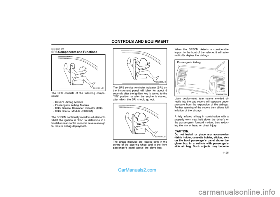
The airbag modules are located both in the centre of the steering wheel and in the frontpassenger's panel above the glove box.
B240B03A-DAT
SRS Components and Functions
B240B01L-D
The SRS consists of the following compo-
nents:
- Driver's Airbag Module
- Passenger's Airbag Module
- SRS Service Reminder Indicator (SRI)
- SRS Control Module (SRSCM)
The SRSCM continually monitors all elements
whilst the ignition is "ON" to determine if a frontal or near-frontal impact is severe enoughto require airbag deployment.
Page 35 of 407
1- 27
CONTROLS AND EQUIPMENT
YT10355A
WARNING:
o Extreme Hazard! Do not use a rearwardfacing child restraint on a seat pro- tected by an airbag in front of it!
o Do not install a child restraint system in the front passenger seat position.
A child restraint system must never beplaced in the front seat. The infant orchild could be severely injured by anairbag deployment in case of an accident.
o Modification to SRS components or wiring, including the addition of anykind of badges to the pad covers ormodifications to the body structure,can adversely affect SRS performanceand lead to possible injury.
WARNING:
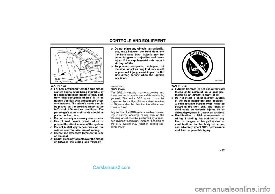
o For best protection from the side airbag
system and to avoid being injured is by the deploying side impact airbag, both front seat occupants should sit in an upright position with the seat belt prop-erly fastened. The driver's hands shouldbe placed on the steering wheel at the9:00 and 3:00 o'clock positions. Thepassenger's arms and hands should beplaced in their laps.
o Do not use any accessory seat covers.
o Use of seat covers could reduce or prevent the effectiveness of the system.
o Do not install any accessories on the side or near the side impact airbag.
o Do not use excessive force on the side of the seat.
o Do not place any objects over the airbag or between the airbag and yourself. B240C03Y-GAT SRS Care The SRS is virtually maintenance-free and there are no parts you can safely service byyourself. The entire SRS system must beinspected by an Hyundai authorised repairerin 10 years after the date that the vehicle wasmanufactured. Any work on the SRS system, such as remov- ing, installing, repairing, or any work on thesteering wheel must be performed by a quali-fied Hyundai technician. Improper handling ofthe SRS system may result in serious per-sonal injury.
HFC2092-DSide airbag sensor
o Do not place any objects (an umbrella,
bag, etc.) between the front door and the front seat. Such objects may be-come dangerous projectiles and causeinjury if the supplemental side impactair bag inflates.
o To prevent unexpected deployment of the side impact air bag that may resultin personal injury, avoid impact to theside airbag sensor when the ignitionkey is on.
Page 36 of 407
CONTROLS AND EQUIPMENT
1- 28
o For cleaning the airbag pad covers,
use only a soft, dry cloth or one which has been moistened with plain water.Solvents or cleaners could adverselyaffect the airbag covers and properdeployment of the system.
o No objects should be placed over or near the airbag modules on the steeringwheel, instrument panel, and the frontpassenger's panel above the glove box,because any such object could causeharm if the vehicle is in a crash severeenough to cause the airbags to inflate.
o If the airbags inflate, they must be re- placed by an Hyundai authorised re-pairer.
o Do not tamper with or disconnect SRS wiring, or other components of the SRSsystem. Doing so could result in injury,due to accidental firing of the airbags orby rendering the SRS inoperative.
o If components of the airbag system must be discarded, or if the vehicle must bescrapped, certain safety precautionsmust be observed. Your Hyundai dealerknows these precautions and can giveyou the necessary information. Failureto follow these precautions and proce-dures could increase the risk of per-sonal injury. o If you sell your vehicle, be sure to
inform the new owner of these impor-tant points and make certain that thismanual is transferred to the new owner.
o If your car was flooded and has soaked carpeting or water on flooring, youshouldn't try to start engine; have thecar towed to Hyundai authorised re-pairer.
o Do not replace the bumper or the bumper guard with the one other thanthe Hyundai genuine parts. Otherwise,it can adversely affect SRS performanceand lead to unexpected injury.
Page 46 of 407
CONTROLS AND EQUIPMENT
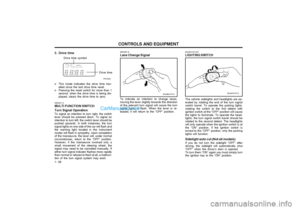
1- 38 The vehicle sidelights and headlights are op- erated by rotating the end of the turn signalswitch barrel. To operate the parking lights,rotating the switch to the first detent withignition switch at the "OFF" position will causethe lights to illuminate. To operate the head-lights, the turn signal switch barrel should berotated to the second detent. The headlightswill only operate when the ignition switch is atthe "ON" position. If the ignition switch isturned to the "OFF" position, only the parkinglights will function. Sidelight auto cut (Not all models) If you do not turn the sidelight "OFF" after driving, the sidelight will automatically shut"OFF" when the driver's door is opened. To turn them "ON" again you must simply turn the ignition key to the "ON" position.
B340C01FC-EAT
LIGHTING SWITCH
SB220A1-E MULTI FUNCTION SWITCH Turn Signal Operation To signal an intention to turn right, the switch lever should be pressed down. To signal anintention to turn left, the switch lever should bepushed upwards. In both instances, the turnsignal lights on one side of the car will flash andthe warning light located in the instrumentcluster will flash in sympathy. Upon completionof the manoeuvre, the lever will, under normal
circumstances, return to the "OFF" position.However, if the manoeuvre involved only asmall movement of the steering wheel, thesignal may need to be cancelled manually. Ifeither turn signal indicator flashes more rapidlythan normal or refuses to flash at all, a malfunc-tion of the turn signal system may exist. SB220B1-E Lane Change Signal To indicate an intention to change lanes, moving the lever slightly towards the directionof the relevant turn signal will cause the turnsignal lights to flash. When the lever is re-leased, it will return to the "OFF" position.
3. Drive time
Drive time symbol
Drive timeHFC2054
o This mode indicates the drive time trav- elled since the last drive time reset.
o Pressing the reset switch for more than 1 second, when the drive time is being dis- played, clears the drive time to zero. B340C01FC-D
B340B01FC-D
Page 47 of 407
1- 39
CONTROLS AND EQUIPMENT
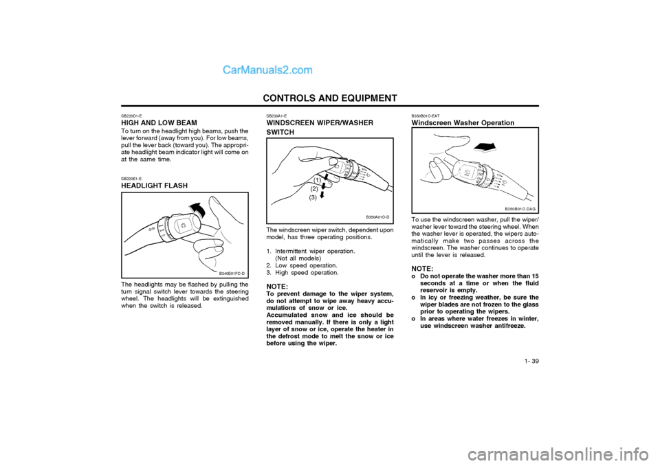
The windscreen wiper switch, dependent upon model, has three operating positions.
1. Intermittent wiper operation.(Not all models)
2. Low speed operation.
3. High speed operation. NOTE: To prevent damage to the wiper system,do not attempt to wipe away heavy accu-mulations of snow or ice. Accumulated snow and ice should be removed manually. If there is only a lightlayer of snow or ice, operate the heater inthe defrost mode to melt the snow or icebefore using the wiper.
SB230A1-E WINDSCREEN WIPER/WASHER SWITCH
SB220E1-E HEADLIGHT FLASH The headlights may be flashed by pulling the turn signal switch lever towards the steeringwheel. The headlights will be extinguishedwhen the switch is released.
SB220D1-E HIGH AND LOW BEAM To turn on the headlight high beams, push the lever forward (away from you). For low beams,pull the lever back (toward you). The appropri-ate headlight beam indicator light will come onat the same time.
B340E01FC-D
B350A01O-D
(1)
(2)
(3)
B350B01O-EAT Windscreen Washer Operation To use the windscreen washer, pull the wiper/ washer lever toward the steering wheel. Whenthe washer lever is operated, the wipers auto-matically make two passes across thewindscreen. The washer continues to operateuntil the lever is released. NOTE:
o Do not operate the washer more than 15 seconds at a time or when the fluid reservoir is empty.
o In icy or freezing weather, be sure the wiper blades are not frozen to the glassprior to operating the wipers.
o In areas where water freezes in winter, use windscreen washer antifreeze. B350B01O.DAG
Page 62 of 407
CONTROLS AND EQUIPMENT
1- 54 B610A01S-DAT HORN (With Airbag) Press the pad of the steering wheel to sound the horn.
B580A01E-EAT
SUN-VISOR
Sun visors are fitted to both the driver and
passenger side of the vehicle. Certain deriva-tives are equipped with a vanity mirror whichis located on the back of the driver andpassenger visor. The visor may be lowered toreduce the amount of glare from directly ahead,or may be moved towards the side window toreduce glare from the side of the vehicle, oncethe inner pivot has been unclipped from thebracket.
NOTE: The Supplemental Restraint System (SRS)
label containing useful information can be found on the back of each sun visor.
WARNING: Do not place the sun-visor in such a man-
ner that it obscures visibility of the road- way, traffic or other objects. SB520A1-F
STEERING WHEEL TILT LEVER
HFC2099HFC2041HFC2094-D
Vanity mirror
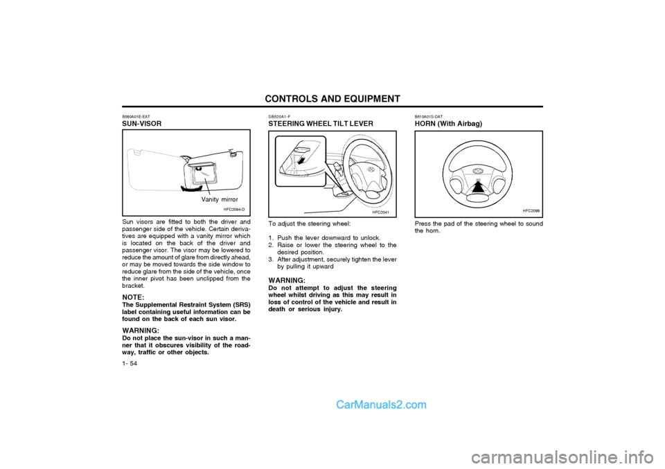
To adjust the steering wheel:
1. Push the lever downward to unlock.
2. Raise or lower the steering wheel to the
desired position.
3. After adjustment, securely tighten the lever by pulling it upward
WARNING: Do not attempt to adjust the steeringwheel whilst driving as this may result inloss of control of the vehicle and result indeath or serious injury.
Page 74 of 407
DRIVING YOUR HYUNDAI
2- 2
C020A01O-EAT BEFORE STARTING THE ENGINEBefore you start the engine, you should al- ways:
1. Look around the vehicle to be sure there
are no flat tyres, puddles of oil or water or other indications of possible trouble.
2. After entering the car, check to be sure the parking brake is engaged.
3. Check that all windows, and lights are clean.
4. Check that the interior and exterior mirrors are clean and in position.
5. Check your seat, seatback and headrestraint to be sure they are in their proper positions.
6. Close all doors.
7. Fasten your seat belt and be sure that all other occupants have fastened theirs.
8. Turn off all lights and accessories that are not needed.
9. When you turn the ignition switch to "ON" check that all appropriate warning lights areoperating and that you have sufficient fuel.
10.Check the operation of warning lights and all bulbs when key is in the "ON" position.
WARNING: (DIESEL ENGINE)To ensure that sufficient vacuum exists within the brake system during cold weath- er start-up conditions, it is necessary to run the engine at idle for several seconds after starting the engine. SC040A1-F COMBINATION IGNITION SWITCH AND STEERING LOCK To Start the Engine
o If your Hyundai is equipped with a manual
transaxle, place the shift lever in neutral and depress the clutch pedal fully.
o If your Hyundai has an automatic transaxle, place the shift lever in "P" (park).
o To start the engine, insert the ignition key and turn it to the "START" position. Re- lease it as soon as the engine starts. Do not hold the key in the "START" position for more that 15 seconds.
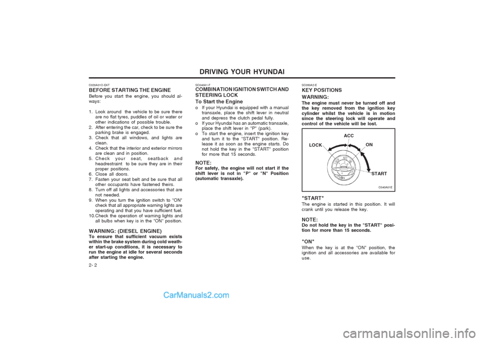
NOTE:For safety, the engine will not start if the shift lever is not in "P" or "N" Position (automatic transaxle). SC050A2-E KEY POSITIONS WARNING: The engine must never be turned off and the key removed from the ignition key cylinder whilst the vehicle is in motion since the steering lock will operate and control of the vehicle will be lost. "START" The engine is started in this position. It will crank until you release the key. NOTE: Do not hold the key in the "START" posi- tion for more than 15 seconds. "ON" When the key is at the "ON" position, the ignition and all accessories are available for use.
C040A01E
LOCK
ACC
ON
START
Page 75 of 407
DRIVING YOUR HYUNDAI 2- 3
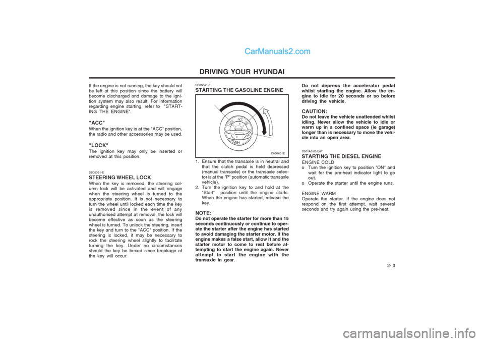
SB050B1-E STEERING WHEEL LOCKWhen the key is removed, the steering col- umn lock will be activated and will engage when the steering wheel is turned to the appropriate position. It is not necessary to turn the wheel until locked each time the key is removed since in the event of any unauthorised attempt at removal, the lock will become effective as soon as the steering wheel is turned. To unlock the steering, insert the key and turn to the "ACC" position. If the steering is locked, it may be necessary to rock the steering wheel slightly to facilitate turning the key. Under no circumstances should the key be forced since breakage of the key will occur. SC060A1-E STARTING THE GASOLINE ENGINE
1. Ensure that the transaxle is in neutral and
that the clutch pedal is held depressed (manual transaxle) or the transaxle selec- tor is at the "P" position (automatic transaxle vehicle).
2. Turn the ignition key to and hold at the "Start" position until the engine starts.When the engine has started, release the key.
NOTE:Do not operate the starter for more than 15seconds continuously or continue to oper- ate the starter after the engine has started to avoid damaging the starter motor. If the engine makes a false start, allow it and the starter motor to come to rest before at- tempting to start the engine again. Never attempt to start the engine with the transaxle in gear.
C050A01E
If the engine is not running, the key should not be left at this position since the battery will become discharged and damage to the igni- tion system may also result. For information regarding engine starting, refer to "START- ING THE ENGINE". "ACC" When the ignition key is at the "ACC" position, the radio and other accessories may be used. "LOCK" The ignition key may only be inserted or removed at this position. Do not depress the accelerator pedal whilst starting the engine. Allow the en- gine to idle for 20 seconds or so before driving the vehicle. CAUTION: Do not leave the vehicle unattended whilstidling. Never allow the vehicle to idle or warm up in a confined space (ie garage) longer than is necessary to move the vehi- cle into an open area.
C051A01O-EAT
STARTING THE DIESEL ENGINE ENGINE COLD
o Turn the ignition key to position "ON" and
wait for the pre-heat indicator light to goout.
o Operate the starter until the engine runs. ENGINE WARM Operate the starter. If the engine does not
respond on the first attempt, wait several seconds and try again using the pre-heat.
Page 77 of 407
DRIVING YOUR HYUNDAI 2- 5
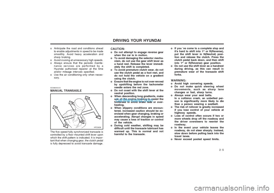
SC090A03-E MANUAL TRANSAXLE
HFC3029
The five speed fully synchronized transaxle is controlled by a floor mounted shift lever upon which the shift pattern is indicated. It is impor- tant that when changing gear, the clutch pedal is fully depressed to avoid transaxle damage. CAUTION:
o Do not attempt to engage reverse gear
when the car is in motion.
o To avoid damaging the selector mecha- nism, do not use the gear shift lever as a hand rest. Release the lever immedi- ately the shift is completed.
o To avoid premature clutch wear, do not use the clutch pedal as a foot rest, anddo not hold the vehicle on a gradient using the clutch.
o Ensure that the engine is not over-revved by upshifting before the tachometerneedle enters the red zone.
o Do not coast with the shift lever at the neutral position.
o When descending long gradients, make use of the engine braking to assist thefootbrake to avoid brake fade or over- heating.
o When slippery conditions are encoun- tered, increased caution should be ex-ercised when gear changing, braking or accelerating. Abrupt changes in speed may cause a loss of traction or control of the vehicle.
o During cold weather, shifting may be difficult until the transaxle lubricant haswarmed up. This is normal and not harmful to the transaxle.
o Anticipate the road and conditions ahead
to enable adjustments in speed to be madesmoothly. Avoid heavy acceleration and sharp braking.
o Avoid cruising at unnecessary high speeds.
o Always ensure that the periodic mainte- nance services are performed by aHyundai authorised repairer at the time and/or mileage intervals specified.
o Use the air conditioning only when neces- sary.
o If you 've come to a complete stop and
it's hard to shift into 1 st
or R(Reverse),
put the shift lever in N(Neutral) posi- tion and release the clutch. Press the clutch pedal back down, and then shift into 1 st
or R(Reverse) gear position.
o Do not use the shift lever as a handrest during driving, as this can result inpremature wear of the transaxle shift forks.
WARNING:
o Avoid high cornering speeds.
o Do not make quick steering wheel movements, such as sharp lanechanges or fast, sharp turns.
o Always wear your seat belts. In a collision crash, an unbelted per- son is significantly more likely to die than a person wearing a seatbelt.
o The risk of rollover is greatly increased
if you lose control of your vehicle at highway speeds.
o Loss of control often occurs if two or
more wheels drop off the roadway andthe driver oversteers to reenter the roadway.
o In the event your vehicle leaves the roadway, do not steer sharply. Instead,slow down before pulling back into the travel lanes.
o Never exceed posted speed limits.