Hyundai Santa Fe 2009 Owner's Manual - RHD (UK, Australia)
Manufacturer: HYUNDAI, Model Year: 2009, Model line: Santa Fe, Model: Hyundai Santa Fe 2009Pages: 269, PDF Size: 9.78 MB
Page 221 of 269
6DO-IT-YOURSELF MAINTENANCE
14
!
FILLING THE WASHER RESERVOIR
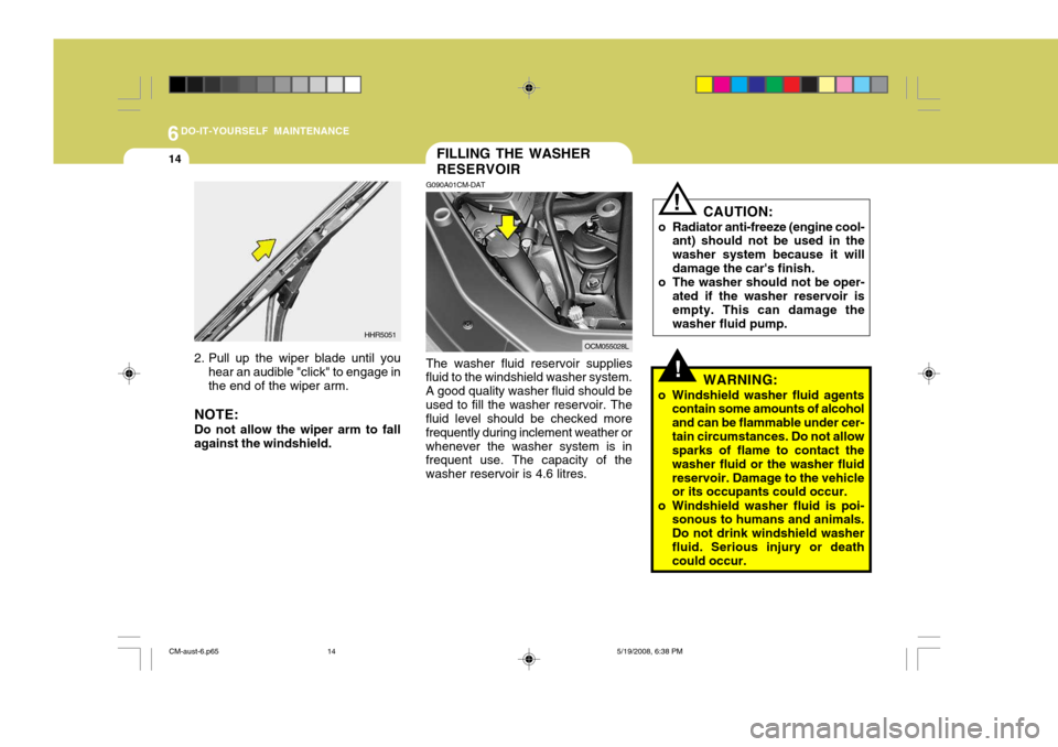
G090A01CM-DAT The washer fluid reservoir supplies
fluid to the windshield washer system. A good quality washer fluid should beused to fill the washer reservoir. The fluid level should be checked more frequently during inclement weather orwhenever the washer system is in frequent use. The capacity of the washer reservoir is 4.6 litres.
2. Pull up the wiper blade until you
hear an audible "click" to engage in the end of the wiper arm.
NOTE: Do not allow the wiper arm to fall against the windshield. HHR5051
OCM055028LCAUTION:
o Radiator anti-freeze (engine cool- ant) should not be used in the washer system because it willdamage the car's finish.
o The washer should not be oper-
ated if the washer reservoir isempty. This can damage the washer fluid pump.
!
WARNING:
o Windshield washer fluid agents contain some amounts of alcohol and can be flammable under cer-tain circumstances. Do not allow sparks of flame to contact the washer fluid or the washer fluidreservoir. Damage to the vehicle or its occupants could occur.
o Windshield washer fluid is poi- sonous to humans and animals. Do not drink windshield washerfluid. Serious injury or death could occur.
CM-aust-6.p65 5/19/2008, 6:38 PM
14
Page 222 of 269
6
DO-IT-YOURSELF MAINTENANCE
15
!
G110C01CM-GAT Transaxle Fluid Capacity See page 9-4.
WARNING:
The transaxle fluid level should be checked when the engine is at nor-mal operating temperature. This means that the engine, radiator, exhaust system etc., are very hot.Exercise great care not to burn your- self during this procedure.
G110B04A-AAT
Recommended Fluid
Your Hyundai automatic transaxle is specially designed to operate with Hyundai Genuine ATF SP-III, DIA- MOND ATF SP-III, SK ATF SP-III orother brands approved by Hyundai Motor Co., Damage caused by a nonspecified fluid is not covered byyour new vehicle limited warranty.
CHECKING THE TRANSAXLE FLUID (AUTOMATIC)
G110A02E-AAT Transaxle fluid in the automatic transaxle should be changed at those intervals specified in the vehicle main-tenance schedule in Section 5. NOTE: Automatic transaxle fluid is a red in color. As driving distance increases, the fluid color turns darkish redgradually. It is a normal condition and you should not judge the need to replace based upon the changingcolor.You must replace the automatictransaxle fluid in accordance withintervals specified in the vehicle maintenance schedule in section 5.
CM-aust-6.p65 5/19/2008, 6:38 PM
15
Page 223 of 269
6DO-IT-YOURSELF MAINTENANCE
16
OCM055037L
G110D02CM-DAT
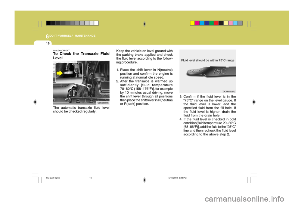
To Check the Transaxle Fluid Level Keep the vehicle on level ground with
the parking brake applied and check the fluid level according to the follow- ing procedure.
1. Place the shift lever in N(neutral)
position and confirm the engine is running at normal idle speed.
2. After the transaxle is warmed up
sufficiently [fluid temperature70~80°C (158~176°F)], for example by 10 minutes usual driving, move the shift lever through all positionsthen place the shift lever in N(neutral) or P(park) position.
The automatic transaxle fluid levelshould be checked regularly.
OCM055006 3. Confirm if the fluid level is in the
“75°C” range on the level gauge. If the fluid level is lower, add the specified fluid from the fill hole. Ifthe fluid level is higher, drain the fluid from the drain hole.
4. If the fluid level is checked in cold condition[fluid temperature 20~30°C (68~86°F)], add the fluid to the “25°C”line and then recheck the fluid level according to the above step 2.
Fluid level should be within 75°C range
CM-aust-6.p65
5/19/2008, 6:38 PM
16
Page 224 of 269
6
DO-IT-YOURSELF MAINTENANCE
17
!WARNING:
The cooling fan is controlled by engine coolant temperature and may sometimes operate even when the engine is not running. Use extremecaution when working near the blades of the cooling fan, so that you are not injured by a rotating fanblade. As the engine coolant tem- perature decreases, the fan will au- tomatically shut off. This is a nor-mal condition.
CHECKING THE BRAKES
G120A01A-AAT
! CAUTION:
Because brakes are essential to the
safe operation of the car, it is sug- gested that they be checked andinspected by your Hyundai dealer. The brakes should be checked and inspected for wear at those intervalsspecified in the vehicle maintenance schedule in Section 5.!WARNING (DIESEL ONLY):
Never work on injection system with
engine running or within 30 sec- onds after shutting off engine. High pressure pump, rail, injectors andhigh pressure pipes are subject to high pressure even after the engine stopped. The fuel jet produced byfuel leaks may cause serious injury, if it touch the body. People using pacemakers should not move than30cm closer to the ECU or wiring harness within the engine room while engine is running, since the high currents in the Common Rail system produce considerable mag-netic fields.
CM-aust-6.p65 5/19/2008, 6:38 PM
17
Page 225 of 269
6DO-IT-YOURSELF MAINTENANCE
18
!
G120E02A-DAT
Adding Brake Fluid
WARNING:
Handle brake fluid carefully. It can
damage your vision if it gets into your eyes. Use only DOT 3 or DOT 4 specification fluid from a sealed container. Do not allow the fluidbottle or reservoir to remain open any longer than required. This will avoid entry of dirt and moisturewhich can damage the brake sys- tem and cause improper operation. To add brake fluid, first wipe away any dirt then unscrew the fluid reservoir cap. Slowly pour the recommendedfluid into the reservoir. Do not overfill. Carefully replace the cap on the reser- voir and tighten.
G120D01CM-AAT
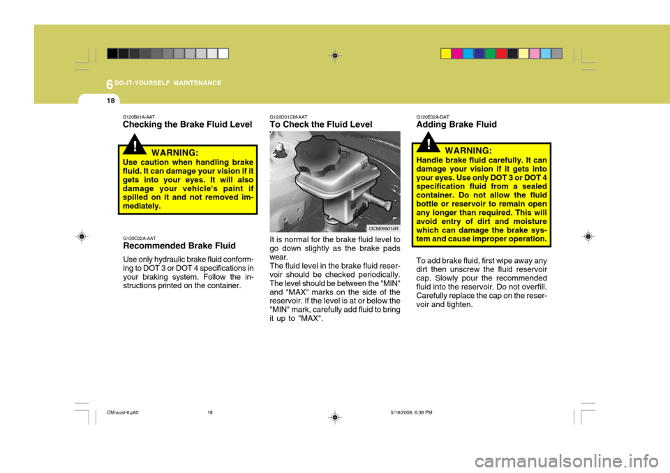
To Check the Fluid Level It is normal for the brake fluid level to
go down slightly as the brake pads wear.
The fluid level in the brake fluid reser-
voir should be checked periodically.The level should be between the "MIN"and "MAX" marks on the side of the reservoir. If the level is at or below the "MIN" mark, carefully add fluid to bringit up to "MAX".
OCM055014R
G120C02A-AAT
Recommended Brake Fluid
Use only hydraulic brake fluid conform- ing to DOT 3 or DOT 4 specifications inyour braking system. Follow the in- structions printed on the container.
!
G120B01A-AAT Checking the Brake Fluid Level
WARNING:
Use caution when handling brake fluid. It can damage your vision if it gets into your eyes. It will alsodamage your vehicle's paint if spilled on it and not removed im- mediately.
CM-aust-6.p65 5/19/2008, 6:38 PM
18
Page 226 of 269
6
DO-IT-YOURSELF MAINTENANCE
19CHANGING THE CLIMATE CONTROL AIR FILTER
B145A01CM-DAT
(For Evaporator and Blower Unit)
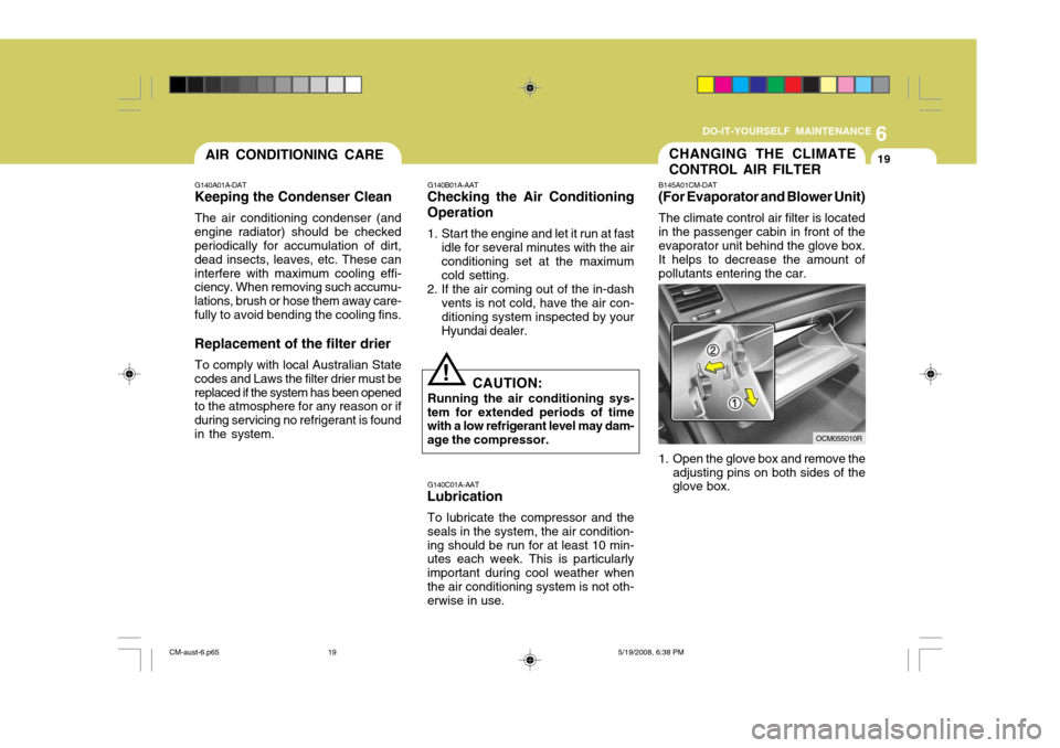
The climate control air filter is located in the passenger cabin in front of the evaporator unit behind the glove box. It helps to decrease the amount of pollutants entering the car.
1. Open the glove box and remove the adjusting pins on both sides of the glove box.
G140C01A-AAT
Lubrication
To lubricate the compressor and the seals in the system, the air condition-ing should be run for at least 10 min- utes each week. This is particularly important during cool weather whenthe air conditioning system is not oth- erwise in use.
!
G140B01A-AAT
Checking the Air Conditioning Operation
1. Start the engine and let it run at fast
idle for several minutes with the air conditioning set at the maximum cold setting.
2. If the air coming out of the in-dash vents is not cold, have the air con-ditioning system inspected by yourHyundai dealer.
CAUTION:
Running the air conditioning sys-
tem for extended periods of time with a low refrigerant level may dam- age the compressor.
OCM055010R
AIR CONDITIONING CARE
G140A01A-DAT
Keeping the Condenser Clean
The air conditioning condenser (and
engine radiator) should be checked periodically for accumulation of dirt, dead insects, leaves, etc. These caninterfere with maximum cooling effi- ciency. When removing such accumu- lations, brush or hose them away care-fully to avoid bending the cooling fins. Replacement of the filter drier
To comply with local Australian State
codes and Laws the filter drier must be replaced if the system has been opened to the atmosphere for any reason or if during servicing no refrigerant is foundin the system.
CM-aust-6.p65 5/19/2008, 6:38 PM
19
Page 227 of 269
6DO-IT-YOURSELF MAINTENANCE
20
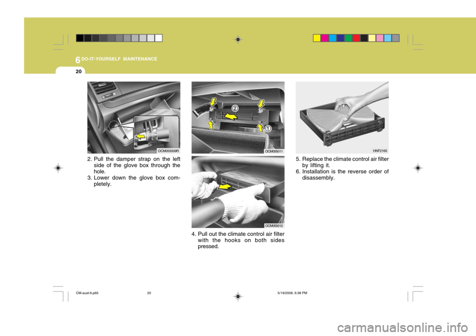
5. Replace the climate control air filterby lifting it.
6. Installation is the reverse order of disassembly.
4. Pull out the climate control air filter with the hooks on both sides pressed.
2. Pull the damper strap on the left
side of the glove box through the hole.
3. Lower down the glove box com-
pletely.
OCM055009ROCM055011
OCM055012
HNF2165
CM-aust-6.p65 5/19/2008, 6:38 PM
20
Page 228 of 269
6
DO-IT-YOURSELF MAINTENANCE
21
G200B02HP-AAT
Replacing Accessory Fuse
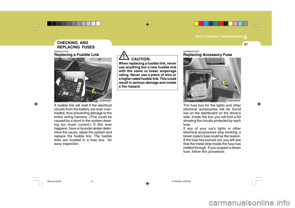
The fuse box for the lights and other electrical accessories will be found low on the dashboard on the driver'sside. Inside the box you will find a list showing the circuits protected by each fuse. If any of your car's lights or other electrical accessories stop working, a blown (open) fuse could be the reason.If the fuse has burned out, you will see that the metal strip inside the fuse has melted through. If you suspect a blownfuse, follow this procedure:
CAUTION:
When replacing a fusible link, never
use anything but a new fusible link with the same or lower amperage rating. Never use a piece of wire ora higher-rated fusible link. This could result in serious damage and create a fire hazard.
!
CHECKING AND REPLACING FUSES
A fusible link will melt if the electrical circuits from the battery are ever over- loaded, thus preventing damage to theentire wiring harness. (This could be caused by a short in the system draw- ing too much current.) If this everhappens, have a Hyundai dealer deter- mine the cause, repair the system and replace the fusible link. The fusiblelinks are located in a fuse box for easy inspection. G200A01A-AAT
Replacing a Fusible Link
OCM054003OCM054002R
CM-aust-6.p65 5/19/2008, 6:38 PM
21
Page 229 of 269
6DO-IT-YOURSELF MAINTENANCE
22
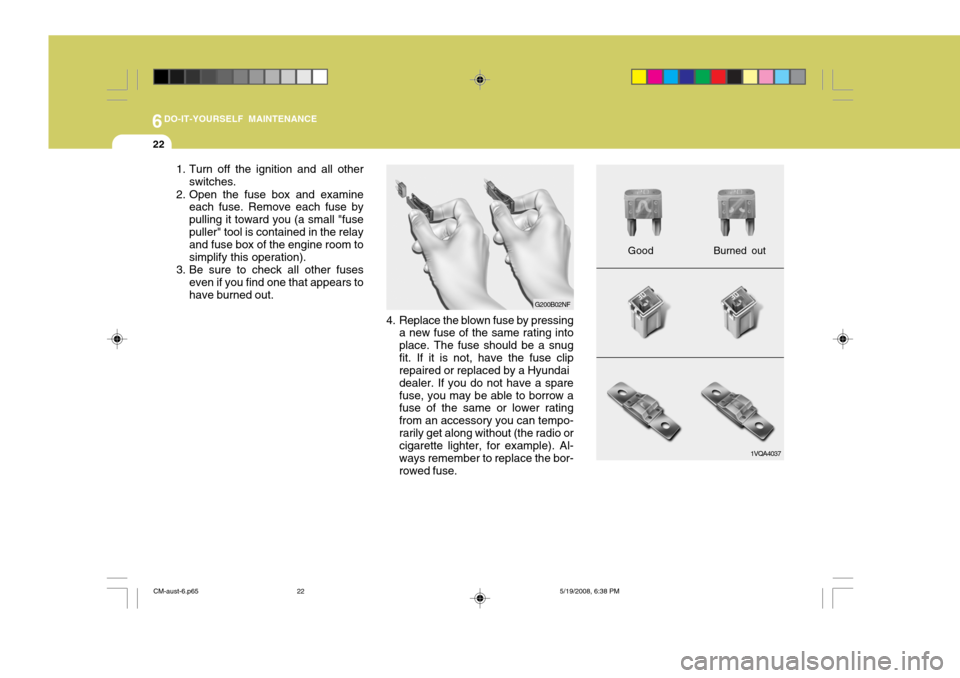
1. Turn off the ignition and all otherswitches.
2. Open the fuse box and examine each fuse. Remove each fuse by pulling it toward you (a small "fusepuller" tool is contained in the relay and fuse box of the engine room to simplify this operation).
3. Be sure to check all other fuses
even if you find one that appears tohave burned out.
4. Replace the blown fuse by pressinga new fuse of the same rating intoplace. The fuse should be a snugfit. If it is not, have the fuse clip repaired or replaced by a Hyundai dealer. If you do not have a sparefuse, you may be able to borrow a fuse of the same or lower rating from an accessory you can tempo-rarily get along without (the radio or cigarette lighter, for example). Al- ways remember to replace the bor-rowed fuse.
G200B02NF
1VQA4037
Good
Burned out
CM-aust-6.p65 5/19/2008, 6:38 PM
22
Page 230 of 269
6
DO-IT-YOURSELF MAINTENANCE
23
CAUTION:
A burned-out fuse indicates that there is a problem in the electrical circuit. If you replace a fuse and it blows as soon as the accessory isturned on, the problem is serious and should be referred to a Hyundai dealer for diagnosis and repair.Never replace a fuse with anything except a fuse with the same or a lower amperage rating. A highercapacity fuse could cause damage and create a fire hazard.
!
NOTE: See page 6-38 for the fuse panel
descriptions. G200C01CM-GAT
Power connector NOTE:
o If the power connector is pulled
out of the fuse panel, the warning chime, audio, clock and interior lamps, etc., will not operate. The following items must be reset af-ter replacement.- Digital clock - Trip computer
- Automatic heating and cooling
control system
- Audio
o Even though the power connec- tor is pulled out, the battery can still be discharged by operation of the headlights or other electri-cal devices.
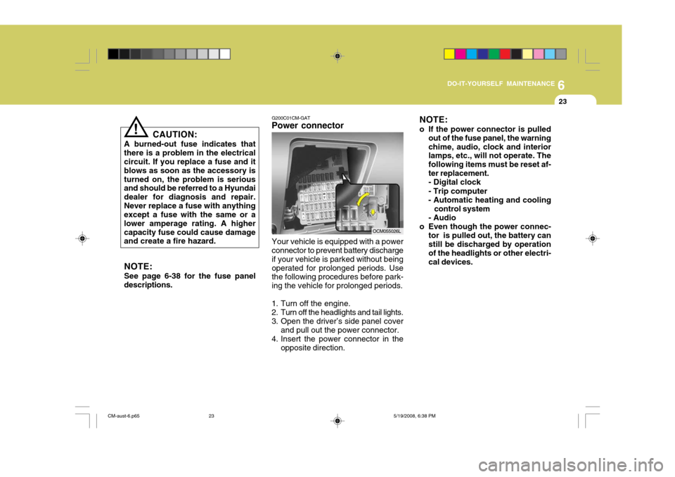
Your vehicle is equipped with a power connector to prevent battery discharge if your vehicle is parked without beingoperated for prolonged periods. Use the following procedures before park- ing the vehicle for prolonged periods.
1. Turn off the engine.
2. Turn off the headlights and tail lights.
3. Open the driver’s side panel cover and pull out the power connector.
4. Insert the power connector in the opposite direction.
OCM055026L
CM-aust-6.p65 5/19/2008, 6:38 PM
23