Hyundai Santa Fe Sport 2017 Owner's Manual
Manufacturer: HYUNDAI, Model Year: 2017, Model line: Santa Fe Sport, Model: Hyundai Santa Fe Sport 2017Pages: 614, PDF Size: 18.99 MB
Page 171 of 614
Features of your vehicle
74
4
5. At the garage door opener receiv-
er (motor-head unit) in the garage,
locate the "learn" or "smart" but-
ton. This can usually be found
where the hanging antenna wire is
attached to the motor-head unit.
6. Firmly press and release the "learn" or "smart" button. (The
name and color of the button vary
by manufacturer). There are 30
seconds to initiate step 7.
7. Return to the vehicle and firmly press, hold for 2 seconds and
release the programmed
HomeLink
®button. Repeat the
"press/hold/release" sequence a
second time, and, depending on
the brand of the garage door
opener (or other rolling code
equipped device), repeat this
sequence a third time to complete
the programming process.
HomeLink
®should now activate your
rolling code equipped device. Gate operator & Canadian
programming
During programming, your handheld
transmitter may automatically stop
transmitting. Continue to press the
Integrated HomeLink
®Wireless
Control System button (note steps 2
through 3 in the Programming por-
tion of this document) while you
press and re-press ("cycle") your
handheld transmitter every two sec-
onds until the frequency signal has
been learned. The indicator light will
flash slowly and then rapidly after
several seconds upon successful
training.
Operating HomeLink
®
To operate, simply press and release
the programmed HomeLink®button.
Activation will now occur for the
trained device (i.e. garage door
opener, gate operator, security sys-
tem, entry door lock, home/office
lighting, etc.). For convenience, the
hand-held transmitter of the device
may also be used at any time. Reprogramming a single
HomeLink
®button
To program a device to HomeLink®
using a HomeLink®button previously
trained, follow these steps:
1.Press and hold the desired HomeLink
®button. DO NOT
release the button.
2.The indicator light will begin to flash after 20 seconds. Without releasing
the HomeLink
®button, proceed
with "Programming" step 2.
For questions or comments, contact
HomeLink
®at www.homelink.comor
1-800-355-3515.
Page 172 of 614
475
Features of your vehicle
Erasing HomeLink®buttons
Individual buttons cannot be erased.
However, to erase all three pro-
grammed buttons:
1. Press and hold the two outer HomeLink
®buttons until the indi-
cator light begins to flash after 10
seconds.
2. Release both buttons. Do not hold for longer than 20 seconds.
The Integrated HomeLink
®Wireless
Control System is now in the training
(learn) mode and can be pro-
grammed at any time following the
appropriate steps in the
Programming sections above. FCC ID: NZLTLMHL4
IC: 4112A-TLMHL4
This device complies with Part 15
of the FCC Rules.
Operation is subject to the following
two conditions:
1. This device may not cause harm-
ful interference, and
2. This device must accept any inter- ference received, including inter-
ference that may cause undesired
operation. NVS
®is a registered trademark and
Z-Nav™ is a trademark of the
Gentex Corporation, Zeeland,
Michigan. HomeLink
®is a registered
trademark owned by Johnson
Controls, Incorporated, Milwaukee,
Wisconsin.
CAUTION
The transceiver has been tested and complies with FCC andIndustry Canada rules. Changesor modifications not expresslyapproved by the party responsi-ble for compliance could voidthe user's authority to operatethe device.
Page 173 of 614
Features of your vehicle
76
4
Side view mirrors
Be sure to adjust mirror angles
before driving.
Your vehicle is equipped with both
left-hand and right-hand side view
mirrors. The mirrors can be adjusted
remotely with the remote switch. The
mirror heads can be folded back to
prevent damage during an automatic
car wash or when passing in a nar-
row street.
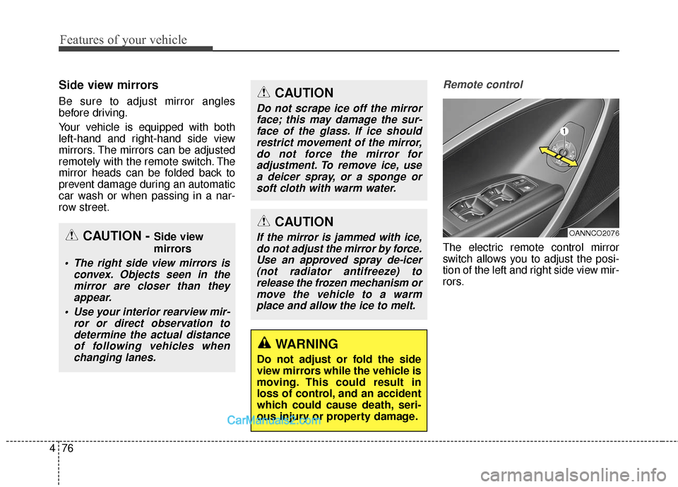
Remote control
The electric remote control mirror
switch allows you to adjust the posi-
tion of the left and right side view mir-
rors.
CAUTION
If the mirror is jammed with ice,
do not adjust the mirror by force.Use an approved spray de-icer(not radiator antifreeze) torelease the frozen mechanism ormove the vehicle to a warmplace and allow the ice to melt.
WARNING
Do not adjust or fold the side
view mirrors while the vehicle is
moving. This could result in
loss of control, and an accident
which could cause death, seri-
ous injury or property damage.
CAUTION
Do not scrape ice off the mirrorface; this may damage the sur-face of the glass. If ice shouldrestrict movement of the mirror,do not force the mirror foradjustment. To remove ice, usea deicer spray, or a sponge orsoft cloth with warm water.
OANNCO2076CAUTION - Side view
mirrors
The right side view mirrors is convex. Objects seen in themirror are closer than theyappear.
Use your interior rearview mir- ror or direct observation todetermine the actual distanceof following vehicles whenchanging lanes.
Page 174 of 614
477
Features of your vehicle
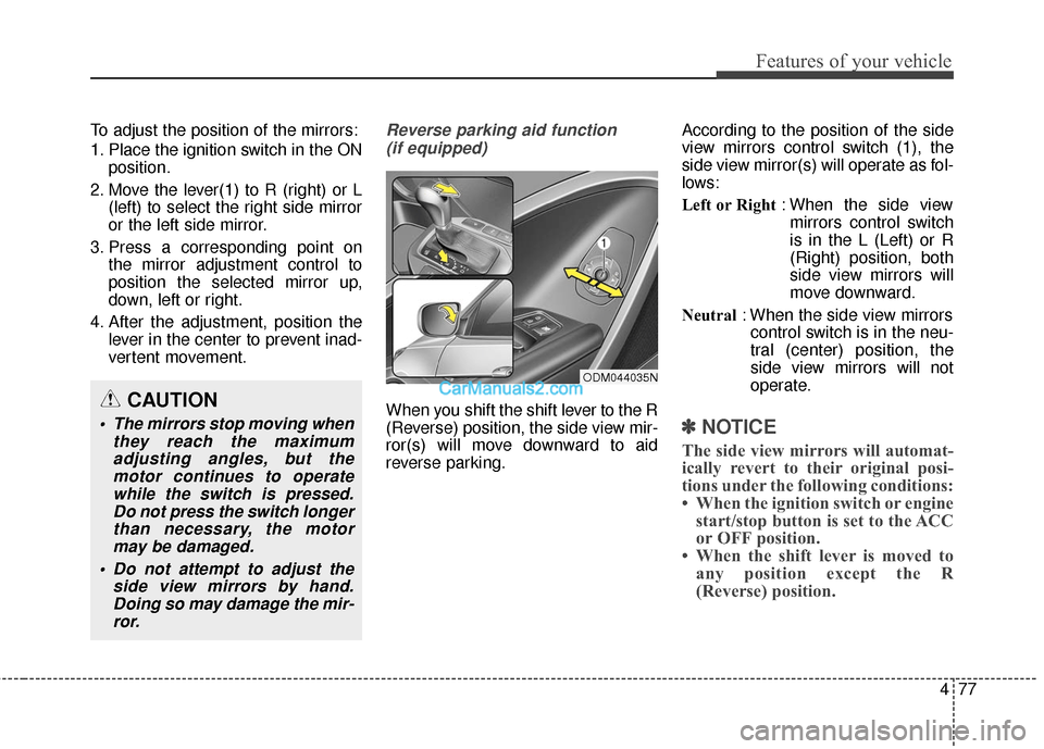
To adjust the position of the mirrors:
1. Place the ignition switch in the ONposition.
2. Move the lever(1) to R (right) or L (left) to select the right side mirror
or the left side mirror.
3. Press a corresponding point on the mirror adjustment control to
position the selected mirror up,
down, left or right.
4. After the adjustment, position the lever in the center to prevent inad-
vertent movement.Reverse parking aid function
(if equipped)
When you shift the shift lever to the R
(Reverse) position, the side view mir-
ror(s) will move downward to aid
reverse parking. According to the position of the side
view mirrors control switch (1), the
side view mirror(s) will operate as fol-
lows:
Left or Right
: When the side view
mirrors control switch
is in the L (Left) or R
(Right) position, both
side view mirrors will
move downward.
Neutral : When the side view mirrors
control switch is in the neu-
tral (center) position, the
side view mirrors will not
operate.
✽ ✽ NOTICE
The side view mirrors will automat-
ically revert to their original posi-
tions under the following conditions:
• When the ignition switch or engine
start/stop button is set to the ACC
or OFF position.
• When the shift lever is moved to any position except the R
(Reverse) position.
CAUTION
The mirrors stop moving when
they reach the maximumadjusting angles, but themotor continues to operatewhile the switch is pressed.Do not press the switch longerthan necessary, the motormay be damaged.
Do not attempt to adjust the side view mirrors by hand.Doing so may damage the mir-ror.
ODM044035N
Page 175 of 614
Features of your vehicle
78
4
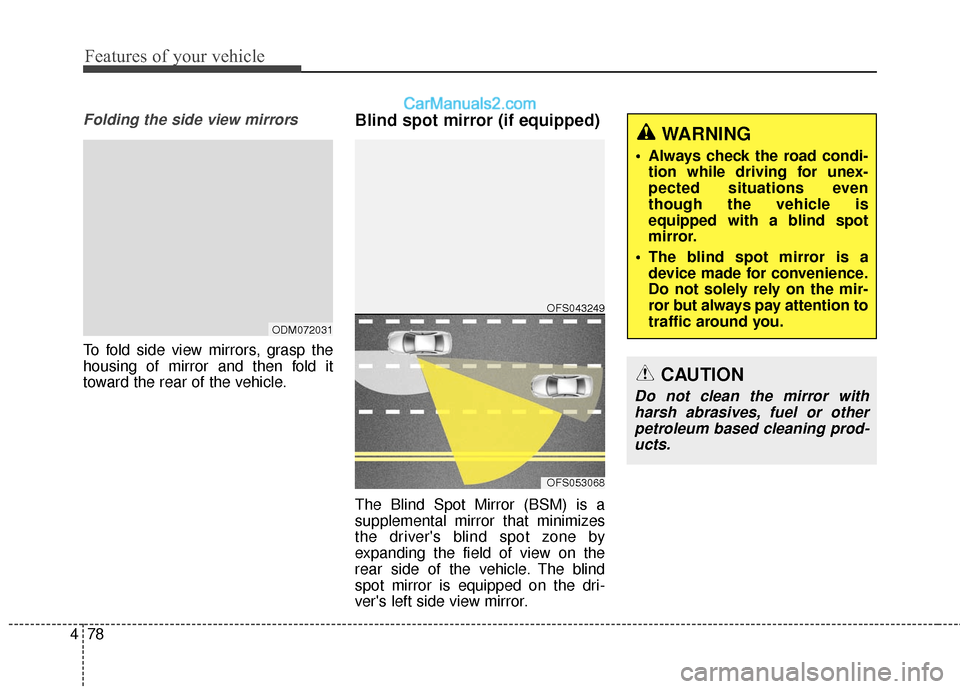
Folding the side view mirrors
To fold side view mirrors, grasp the
housing of mirror and then fold it
toward the rear of the vehicle.
Blind spot mirror (if equipped)
The Blind Spot Mirror (BSM) is a
supplemental mirror that minimizes
the driver's blind spot zone by
expanding the field of view on the
rear side of the vehicle. The blind
spot mirror is equipped on the dri-
ver's left side view mirror.
ODM072031
OFS053068
OFS043249
WARNING
Always check the road condi-
tion while driving for unex-
pected situations even
though the vehicle is
equipped with a blind spot
mirror.
The blind spot mirror is a device made for convenience.
Do not solely rely on the mir-
ror but always pay attention to
traffic around you.
CAUTION
Do not clean the mirror withharsh abrasives, fuel or otherpetroleum based cleaning prod-ucts.
Page 176 of 614
479
Features of your vehicle
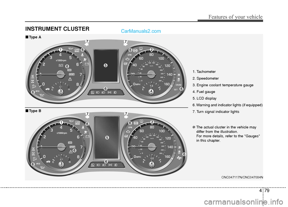
INSTRUMENT CLUSTER
1. Tachometer
2. Speedometer
3. Engine coolant temperature gauge
4. Fuel gauge
5. LCD display
6. Warning and indicator lights (if equipped)
7. Turn signal indicator lights
ONC047117N/ONC047084N
■
■Type A
❈The actual cluster in the vehicle may
differ from the illustration.
For more details, refer to the "Gauges"
in this chapter.
■
■ Type B
Page 177 of 614
Features of your vehicle
80
4
Instrument Cluster Control
Adjusting Instrument Cluster
Illumination
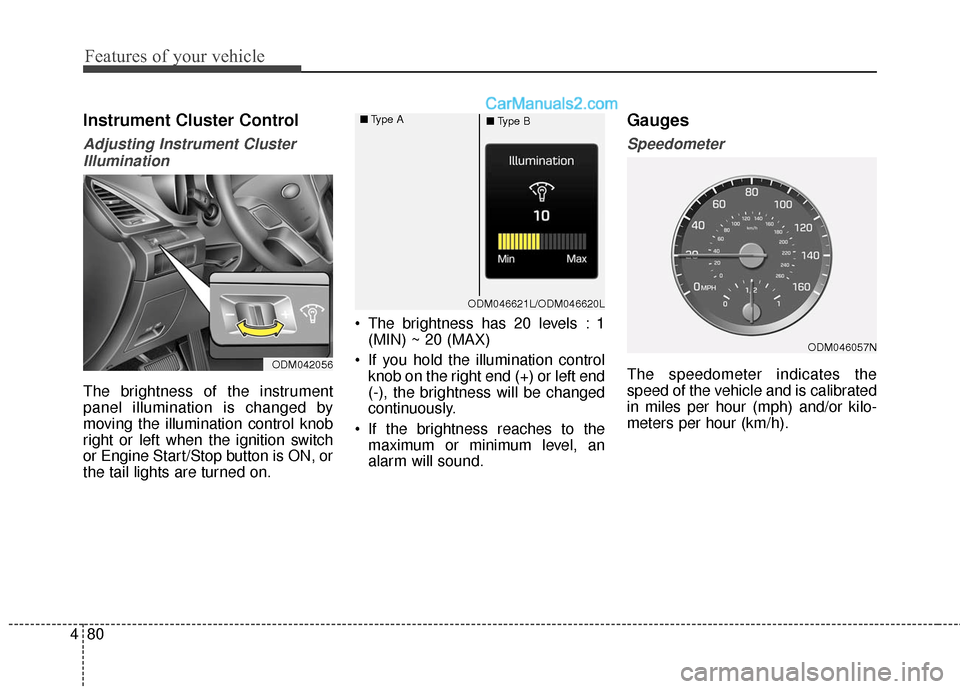
The brightness of the instrument
panel illumination is changed by
moving the illumination control knob
right or left when the ignition switch
or Engine Start/Stop button is ON, or
the tail lights are turned on. The brightness has 20 levels : 1
(MIN) ~ 20 (MAX)
If you hold the illumination control knob on the right end (+) or left end
(-), the brightness will be changed
continuously.
If the brightness reaches to the maximum or minimum level, an
alarm will sound.
Gauges
Speedometer
The speedometer indicates the
speed of the vehicle and is calibrated
in miles per hour (mph) and/or kilo-
meters per hour (km/h).ODM042056
ODM046057N
ODM046621L/ODM046620L
■
Type A
■Type B
Page 178 of 614
481
Features of your vehicle
Tachometer
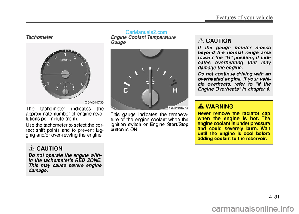
The tachometer indicates the
approximate number of engine revo-
lutions per minute (rpm).
Use the tachometer to select the cor-
rect shift points and to prevent lug-
ging and/or over-revving the engine.
Engine Coolant TemperatureGauge
This gauge indicates the tempera-
ture of the engine coolant when the
ignition switch or Engine Start/Stop
button is ON.
CAUTION
Do not operate the engine with-in the tachometer's RED ZONE.This may cause severe enginedamage.
ODM046733
ODM046734WARNING
Never remove the radiator cap
when the engine is hot. The
engine coolant is under pressure
and could severely burn. Wait
until the engine is cool before
adding coolant to the reservoir.
CAUTION
If the gauge pointer movesbeyond the normal range areatoward the “H” position, it indi-cates overheating that maydamage the engine.
Do not continue driving with anoverheated engine. If your vehi-cle overheats, refer to “If theEngine Overheats” in chapter 6.
Page 179 of 614
Features of your vehicle
82
4
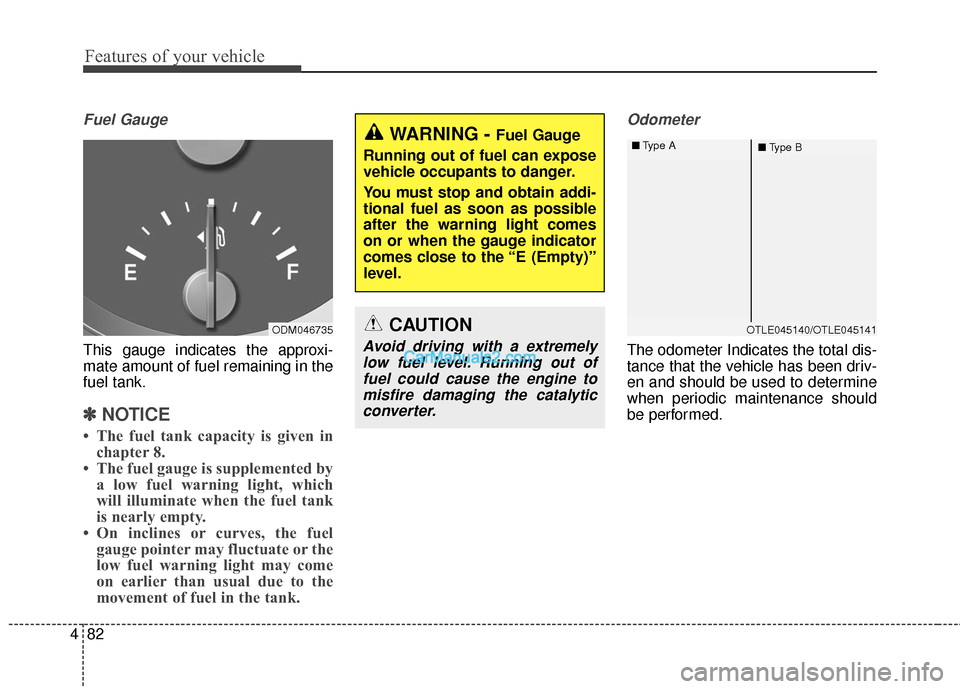
Fuel Gauge
This gauge indicates the approxi-
mate amount of fuel remaining in the
fuel tank.
✽ ✽
NOTICE
• The fuel tank capacity is given in
chapter 8.
• The fuel gauge is supplemented by a low fuel warning light, which
will illuminate when the fuel tank
is nearly empty.
• On inclines or curves, the fuel gauge pointer may fluctuate or the
low fuel warning light may come
on earlier than usual due to the
movement of fuel in the tank.
Odometer
The odometer Indicates the total dis-
tance that the vehicle has been driv-
en and should be used to determine
when periodic maintenance should
be performed.
ODM046735
WARNING - Fuel Gauge
Running out of fuel can expose
vehicle occupants to danger.
You must stop and obtain addi-
tional fuel as soon as possible
after the warning light comes
on or when the gauge indicator
comes close to the “E (Empty)”
level.
CAUTION
Avoid driving with a extremely low fuel level. Running out offuel could cause the engine tomisfire damaging the catalyticconverter.
OTLE045140/OTLE045141
■
Type A
■Type B
Page 180 of 614
483
Features of your vehicle
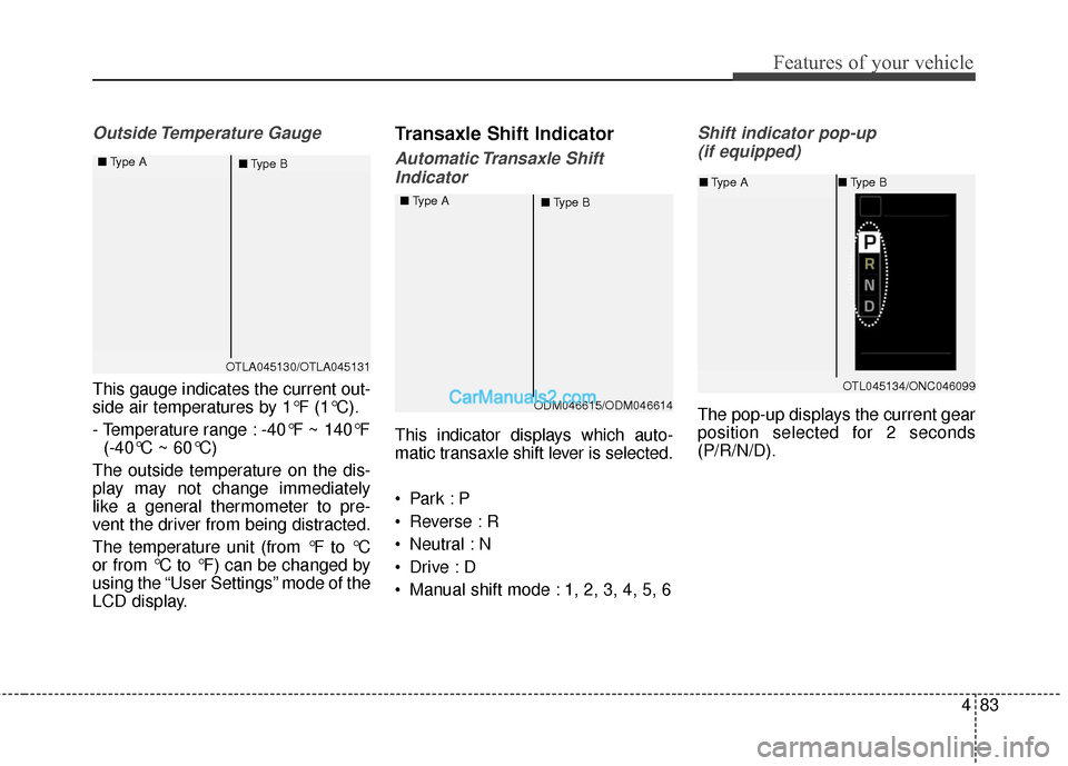
Outside Temperature Gauge
This gauge indicates the current out-
side air temperatures by 1°F (1°C).
- Temperature range : -40°F ~ 140°F (-40°C ~ 60°C)
The outside temperature on the dis-
play may not change immediately
like a general thermometer to pre-
vent the driver from being distracted.
The temperature unit (from °F to °C
or from °C to °F) can be changed by
using the “User Settings” mode of the
LCD display.
Transaxle Shift Indicator
Automatic Transaxle Shift Indicator
This indicator displays which auto-
matic transaxle shift lever is selected.
Reverse : R
Neutral : N
Manual shift mode : 1, 2, 3, 4, 5, 6
Shift indicator pop-up (if equipped)
The pop-up displays the current gear
position selected for 2 seconds
(P/R/N/D).
OTLA045130/OTLA045131
■
Type A
■Type B
ODM046615/ODM046614
■
Type A
■Type B
OTL045134/ONC046099
■Type A ■Type B