Hyundai Terracan 2005 Owner's Manual
Manufacturer: HYUNDAI, Model Year: 2005, Model line: Terracan, Model: Hyundai Terracan 2005Pages: 539, PDF Size: 18.03 MB
Page 361 of 539
1CONTROLS AND EQUIPMENT
56
!
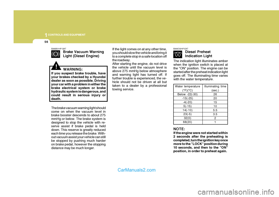
B265B01HP-GAT
Brake Vacuum Warning Light (Diesel Engine)
The brake vacuum warning light should come on when the vacuum level in brake booster descends to about 275 mmHg or below. The brake system isdesigned to stop the vehicle with re- serve assist if brake pedal is held down. This reserve is greatly reducedeach time you release the brake. With- out vacuum assist your vehicle can still be stopped by pushing much harderon brake pedal, however the stopping distance may be much longer. WARNING:
If you suspect brake trouble, have your brakes checked by a Hyundai dealer as soon as possible. Driving your car with a problem in either thebrake electrical system or brake hydraulic system is dangerous, and could result in serious injury ordeath.If the light comes on at any other time, you should slow the vehicle and bring itto a complete stop in a safe location off the roadway. After starting the engine, do not drivethe vehicle until the vacuum level is above 275 mmHg below atmosphere and warning light has turned off. Iffurther trouble is experienced, the ve- hicle should not be driven at all but taken to a dealer by a professionaltowing service. B265C02HP-EAT
Diesel Preheat Indication Light
Water temperature
(°F)(°C)
Below -22(-30) -13(-25)
-4(-20)5(-15)
14(-10) 23(-5)32(0)
68(20) Illuminating time
(sec.)26 201510
5.53.5 21
NOTE: If the engine were not started within 2 seconds after the preheating is completed, turn the ignition key once more to the "LOCK" position during10 seconds, and then to the "ON" position, in order to preheat again.
The indication light illuminates amber when the ignition switch is placed at the "ON" position. The engine can be started after the preheat indication lightgoes off. The illuminating time varies with the water temperature.
Page 362 of 539
1
CONTROLS AND EQUIPMENT
57
!
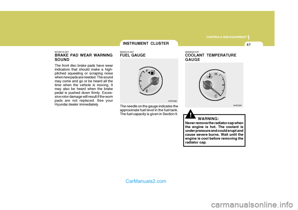
B270A01A-GAT BRAKE PAD WEAR WARNING SOUND The front disc brake pads have wear indicators that should make a high-pitched squealing or scraping noise when new pads are needed. The sound may come and go or be heard all thetime when the vehicle is moving. It may also be heard when the brake pedal is pushed down firmly. Exces-sive rotor damage will result if the worn pads are not replaced. See your Hyundai dealer immediately. B290A02A-EAT COOLANT TEMPERATURE GAUGE
The needle on the gauge indicates the approximate fuel level in the fuel tank. The fuel capacity is given in Section 9. WARNING:
Never remove the radiator cap when the engine is hot. The coolant is under pressure and could erupt and cause severe burns. Wait until theengine is cool before removing the radiator cap.
INSTRUMENT CLUSTER
B280A01A-AAT FUEL GAUGE
HHP2080
HHP2081
Page 363 of 539
1CONTROLS AND EQUIPMENT
58
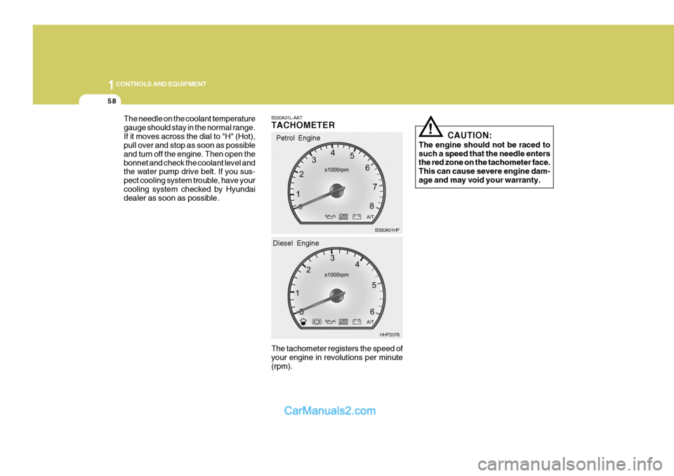
The needle on the coolant temperature gauge should stay in the normal range.If it moves across the dial to "H" (Hot), pull over and stop as soon as possible and turn off the engine. Then open thebonnet and check the coolant level and the water pump drive belt. If you sus- pect cooling system trouble, have yourcooling system checked by Hyundai dealer as soon as possible.
! CAUTION:
The engine should not be raced to such a speed that the needle enters the red zone on the tachometer face. This can cause severe engine dam-age and may void your warranty.
B330A01L-AAT TACHOMETER The tachometer registers the speed of your engine in revolutions per minute (rpm).Petrol Engine
B330A01HP
HHP2078
Diesel Engine
Page 364 of 539
1
CONTROLS AND EQUIPMENT
59
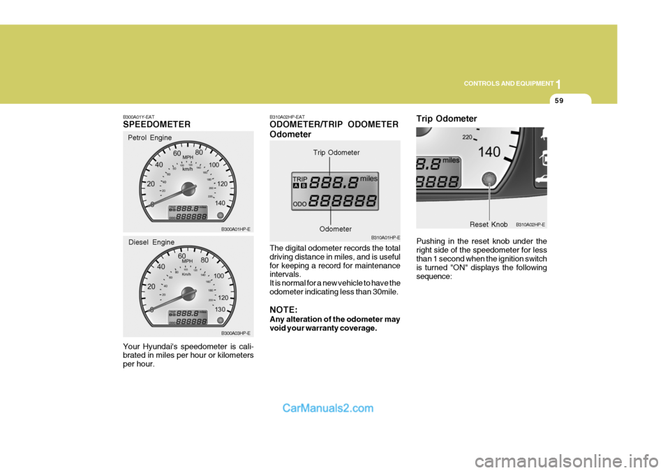
B300A01Y-EAT SPEEDOMETER Your Hyundai's speedometer is cali- brated in miles per hour or kilometers per hour. Petrol Engine
B300A01HP-E B300A03HP-E
Diesel EngineB310A02HP-EAT ODOMETER/TRIP ODOMETER Odometer The digital odometer records the total driving distance in miles, and is usefulfor keeping a record for maintenance intervals. It is normal for a new vehicle to have theodometer indicating less than 30mile. NOTE: Any alteration of the odometer may void your warranty coverage. B310A01HP-E
Trip Odometer
Odometer
B310A02HP-E
Reset Knob
Trip Odometer Pushing in the reset knob under the right side of the speedometer for less than 1 second when the ignition switch is turned "ON" displays the followingsequence:
Page 365 of 539
1CONTROLS AND EQUIPMENT
60
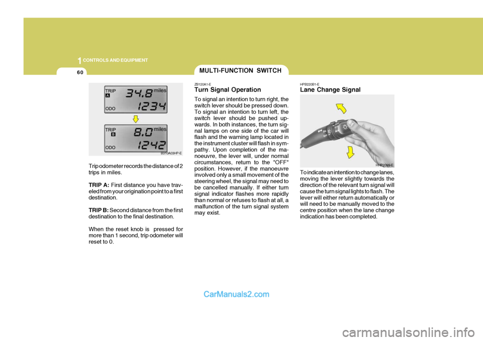
HPB220B1-E Lane Change Signal To indicate an intention to change lanes, moving the lever slightly towards the direction of the relevant turn signal will cause the turn signal lights to flash. Thelever will either return automatically or will need to be manually moved to the centre position when the lane changeindication has been completed.MULTI-FUNCTION SWITCH
ZB120A1-E Turn Signal Operation To signal an intention to turn right, the switch lever should be pressed down.To signal an intention to turn left, the switch lever should be pushed up- wards. In both instances, the turn sig-nal lamps on one side of the car will flash and the warning lamp located in the instrument cluster will flash in sym-pathy. Upon completion of the ma- noeuvre, the lever will, under normal circumstances, return to the "OFF"position. However, if the manoeuvre involved only a small movement of the steering wheel, the signal may need tobe cancelled manually. If either turn signal indicator flashes more rapidly than normal or refuses to flash at all, amalfunction of the turn signal system may exist.
HHP2099-E
B310A03HP-E
Trip odometer records the distance of 2 trips in miles. TRIP A: First distance you have trav-
eled from your origination point to a first destination. TRIP B: Second distance from the first
destination to the final destination.When the reset knob is pressed for more than 1 second, trip odometer will reset to 0.
Page 366 of 539
1
CONTROLS AND EQUIPMENT
61
ZB120D1-E HIGH AND LOW BEAM
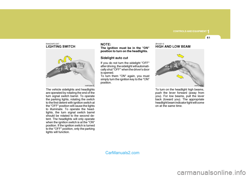
B340C03FC-EATLIGHTING SWITCH The vehicle sidelights and headlights are operated by rotating the end of the turn signal switch barrel. To operate the parking lights, rotating the switchto the first detent with ignition switch at the "OFF" position will cause the lights to illuminate. To operate the head-lights, the turn signal switch barrel should be rotated to the second de- tent. The headlights will only operatewhen the ignition switch is at the "ON" position. If the ignition switch is turned to the "OFF" position, only the parkinglights will function.
HHP2094-E NOTE: The ignition must be in the "ON" position to turn on the headlights. Sidelight auto cut If you do not turn the sidelight "OFF" after driving, the sidelight will automati-cally shut "OFF" when the driver's door is opened. To turn them "ON" again, you mustsimply turn the ignition key to the "ON" position.HHP2097-E
To turn on the headlight high beams, push the lever forward (away from you). For low beams, pull the lever back (toward you). The appropriateheadlight beam indicator light will come on at the same time.
Page 367 of 539
1CONTROLS AND EQUIPMENT
62FOG LIGHT SWITCH
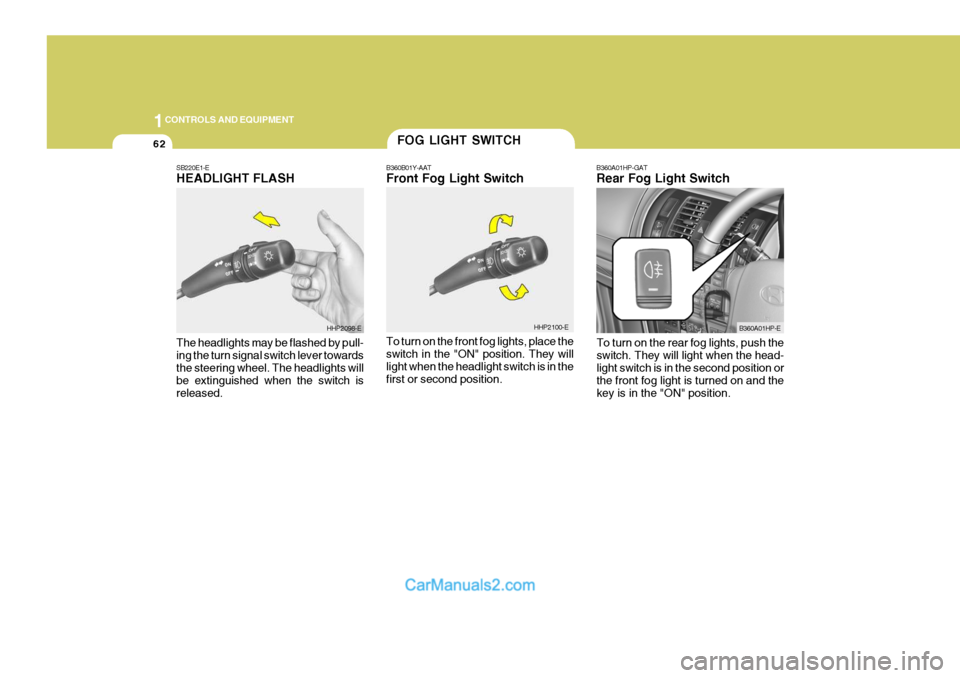
B360B01Y-AAT Front Fog Light Switch To turn on the front fog lights, place the switch in the "ON" position. They will light when the headlight switch is in thefirst or second position. B360A01HP-GAT Rear Fog Light Switch
HHP2100-E B360A01HP-E
SB220E1-EHEADLIGHT FLASH The headlights may be flashed by pull- ing the turn signal switch lever towards the steering wheel. The headlights will be extinguished when the switch isreleased.
HHP2098-E
To turn on the rear fog lights, push the switch. They will light when the head- light switch is in the second position or the front fog light is turned on and thekey is in the "ON" position.
Page 368 of 539
1
CONTROLS AND EQUIPMENT
63
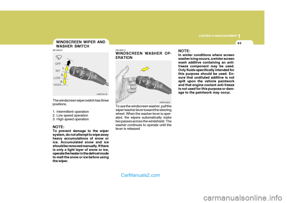
The windscreen wiper switch has three positions.
1. Intermittent operation
2. Low speed operation
3. High speed operation NOTE: To prevent damage to the wiper system, do not attempt to wipe awayheavy accumulations of snow or ice. Accumulated snow and ice should be removed manually. If thereis only a light layer of snow or ice, operate the heater in the defrost mode to melt the snow or ice before usingthe wiper.WINDSCREEN WIPER AND WASHER SWITCH
ZB130A2-E
HHP2101-E
1
OB130B1-E WINDSCREEN WASHER OP- ERATION To use the windscreen washer, pull the wiper/washer lever toward the steeringwheel. When the washer lever is oper- ated, the wipers automatically make two passes across the windshield. Thewasher continues to operate until the lever is released. NOTE: In winter conditions where screen washer icing occurs, a winter screen wash additive containing an anti-freeze component may be used. Only fluids specifically intended for this purpose should be used. En-sure that undiluted additive is not spilt upon the vehicle paintwork and that engine coolant anti-freezeis not used for this purpose or dam- age to the paintwork may occur.
HHP2103-E
2 3
Page 369 of 539
1CONTROLS AND EQUIPMENT
64
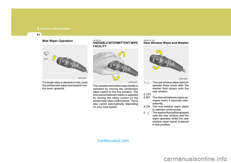
OB140A1-E VARIABLE INTERMITTENT WIPE FACILITY The variable intermittent wipe facility is operated by moving the windscreen wiper switch to the first position. The time period between wipes is adjustedby moving the rotary control on the windscreen wiper switch barrel. This is also varied automatically dependingon your road speed.
HHP2102-E
HHP2108-E
Mist Wiper Operation If a single wipe is desired in mist, push the windscreen wiper and washer con- trol lever upwards.HHP2104-E
B390A01E-EAT Rear Window Wiper and Washer
1. : The rear window wiper starts to
operate three times after the washer fluid sprays onto the rear window.
2.OFF 3.INT: The interval between wipes op- erates every 5 seconds inter-mittently.
4.ON : The rear window wiper starts
to operate continuously.
5. : The washer fluid will be sprayed onto the rear window and thewiper operates whilst the rearwindow wiper barrel is placed in this position.
Page 370 of 539
1
CONTROLS AND EQUIPMENT
65
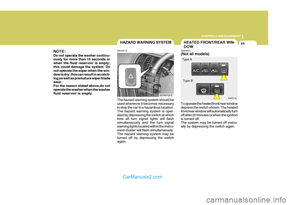
The hazard warning system should be used whenever it becomes necessary to stop the car in a hazardous location. The hazard warning system is oper-ated by depressing the switch at which time all turn signal lights will flash simultaneously and the turn signalwarning lights located within the instru- ment cluster will flash simultaneously. The hazard warning system may beturned off by depressing the switch again.HAZARD WARNING SYSTEM
SB240A1-E
B370A01HP-E
NOTE: Do not operate the washer continu- ously for more than 15 seconds or when the fluid reservoir is empty;this could damage the system. Do not operate the wiper when the win- dow is dry; this can result in scratch-ing as well as premature wiper blade wear. For the reason stated above,do notoperate the washer when the washer fluid reservoir is empty.
To operate the heated front/rear window depress the switch shown. The heated front/rear window will automatically turn off after 20 minutes or when the ignitionis turned off. The system may be turned off manu- ally by depressing the switch again.
HEATED FRONT/REAR WIN- DOW
SB250A2-E (Not all models)
HHP2119
Type A
Type B