driver seat adjustment Hyundai Terracan 2006 Owner's Manual
[x] Cancel search | Manufacturer: HYUNDAI, Model Year: 2006, Model line: Terracan, Model: Hyundai Terracan 2006Pages: 539, PDF Size: 18.11 MB
Page 35 of 539
1
FEATURES OF YOUR HYUNDAI
21
!
!
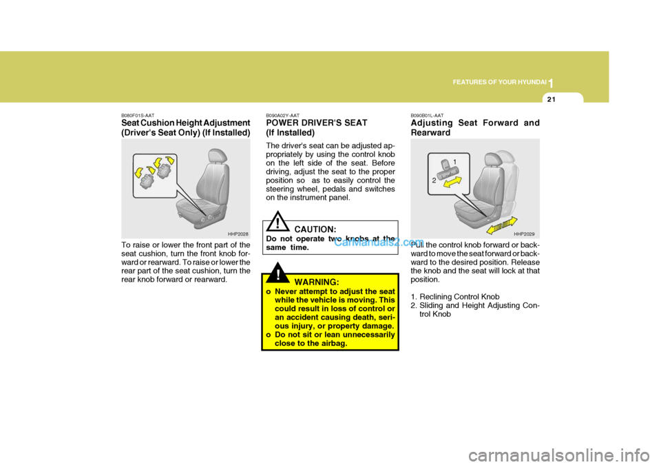
B090A02Y-AAT POWER DRIVER'S SEAT (If Installed) The driver's seat can be adjusted ap- propriately by using the control knobon the left side of the seat. Before driving, adjust the seat to the proper position so as to easily control thesteering wheel, pedals and switches on the instrument panel.
CAUTION:
Do not operate two knobs at the same time.
WARNING:
o Never attempt to adjust the seat while the vehicle is moving. Thiscould result in loss of control oran accident causing death, seri- ous injury, or property damage.
o Do not sit or lean unnecessarily close to the airbag. B090B01L-AAT Adjusting Seat Forward and Rearward Pull the control knob forward or back- ward to move the seat forward or back-ward to the desired position. Release the knob and the seat will lock at that position.
1. Reclining Control Knob
2. Sliding and Height Adjusting Con-
trol Knob
B080F01S-AAT Seat Cushion Height Adjustment (Driver's Seat Only) (If Installed) To raise or lower the front part of the seat cushion, turn the front knob for-ward or rearward. To raise or lower the rear part of the seat cushion, turn the rear knob forward or rearward.
HHP2028
HHP2029
1
2
Page 36 of 539
1FEATURES OF YOUR HYUNDAI
22
!
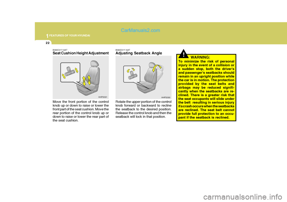
B090D01Y-AAT Adjusting Seatback Angle Rotate the upper portion of the control knob forward or backward to recline the seatback to the desired position.Release the control knob and then the seatback will lock in that position. WARNING:
To minimize the risk of personal injury in the event of a collision or a sudden stop, both the driver's and passenger's seatbacks shouldremain in an upright position while the car is in motion. The protection provided by the seat belts andairbags may be reduced signifi- cantly when the seatbacks are re- clined. There is a greater risk thatthe seat occupants will slide under the belt resulting in serious injury if a crash occurs when the seatbacksare reclined. The seat belt cannot provide full protection to an occu- pant if the seatback is reclined.
B090C01Y-AAT Seat Cushion Height Adjustment Move the front portion of the control knob up or down to raise or lower the front part of the seat cushion. Move therear portion of the control knob up or down to raise or lower the rear part of the seat cushion.
HHP2031
HHP2030
Page 48 of 539
1FEATURES OF YOUR HYUNDAI
34
will extend and let you move around. If there is a sudden stop or impact, how-ever, the belt will lock into position. It will also lock if you try to lean forward too quickly. B180A02Y-GAT SEAT BELTS-3-Point System with Emergency Locking Retrac- tor (If Installed) To Fasten Your Belt
!
lower it, push it down while pressing the height adjuster button.Release the button to lock the anchor into position. Try sliding the height adjuster to make sure that it has lockedinto the position.
WARNING:
o The height adjuster must be in the locked position when thevehicle is moving.
o Misadjustment of shoulder belt
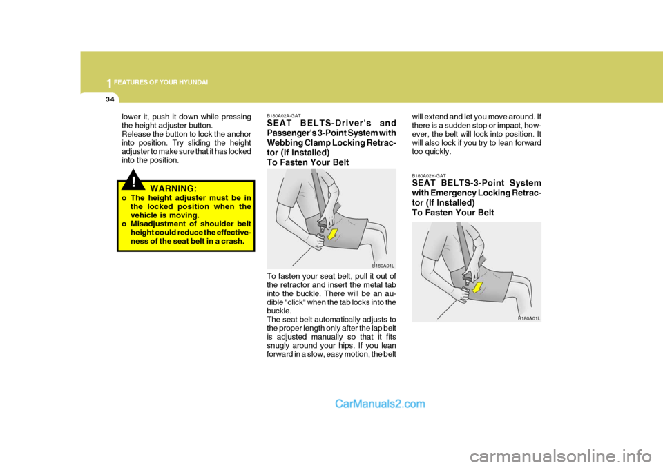
height could reduce the effective- ness of the seat belt in a crash. B180A02A-GAT SEAT BELTS-Driver's and Passenger's 3-Point System withWebbing Clamp Locking Retrac-tor (If Installed)To Fasten Your Belt To fasten your seat belt, pull it out of the retractor and insert the metal tab into the buckle. There will be an au-dible "click" when the tab locks into the buckle. The seat belt automatically adjusts tothe proper length only after the lap belt is adjusted manually so that it fits snugly around your hips. If you leanforward in a slow, easy motion, the belt
B180A01L
B180A01L
Page 267 of 539
6 DO-IT-YOURSELF MAINTENANCE
40
1. Keep all tires inflated to the correct
pressure.
2. Place the vehicle on level ground and press the front bumper & rear bumper down several times. Placevehicle at a distance of 3m (118.1 in.) from the test wall.
3. See that the vehicle is unloaded (except for full levels of coolant, engine oil and fuel, and spare tire,jack, and tools). Have the driver or equivalent weight placed in driver's seat.
4. Clean the headlight lens and turn on the headlight.
5. Open the hood.
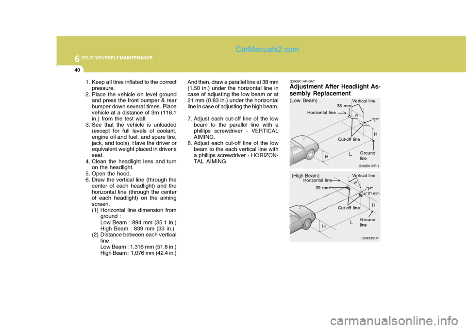
6. Draw the vertical line (through the center of each headlight) and thehorizontal line (through the center of each headlight) on the aiming screen.
(1) Horizontal line dimension from
ground : Low Beam : 894 mm (35.1 in.) High Beam : 839 mm (33 in.)
(2) Distance between each vertical line : Low Beam : 1,316 mm (51.8 in.) High Beam : 1,076 mm (42.4 in.) And then, draw a parallel line at 38 mm
(1.50 in.) under the horizontal line incase of adjusting the low beam or at 21 mm (0.83 in.) under the horizontal line in case of adjusting the high beam.
7. Adjust each cut-off line of the low beam to the parallel line with a phillips screwdriver - VERTICAL AIMING.
8. Adjust each cut-off line of the low beam to the each vertical line witha phillips screwdriver - HORIZON-TAL AIMING. G290B01HP-GAT
Adjustment After Headlight As- sembly Replacement
G290B02HP
LW
H Cut-off line
"P"
Vertical line
Horizontal line
Ground line
21 mm39 mm
(High Beam)
H
G290B01HP-1
LW
"P"
38 mm
H
H
(Low Beam)
Vertical line
Ground line
Cut-off line
Horizontal line
Page 327 of 539
1
CONTROLS AND EQUIPMENT
19
!
!
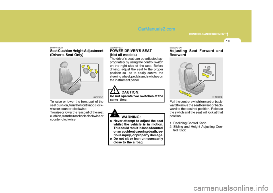
B080F01S-EAT Seat Cushion Height Adjustment (Driver's Seat Only) To raise or lower the front part of the seat cushion, turn the front knob clock- wise or counter-clockwise. To raise or lower the rear part of the seatcushion, turn the rear knob clockwise or counter-clockwise. B090A02Y-EAT POWER DRIVER'S SEAT (Not all models) The driver's seat can be adjusted ap- propriately by using the control switch on the right side of the seat. Beforedriving, adjust the seat to the proper position so as to easily control the steering wheel, pedals and switches onthe instrument panel.
CAUTION:
Do not operate two switches at thesame time.
WARNING:
o Never attempt to adjust the seat whilst the vehicle is in motion.This could result in loss of controlor an accident causing death, se- rious injury, or property damage.
o Do not sit or lean unnecessarily close to the airbag.
HHP2028-E B090B01L-EAT Adjusting Seat Forward and Rearward Pull the control switch forward or back- ward to move the seat forward or back- ward to the desired position. Release the switch and the seat will lock at thatposition.
1. Reclining Control Knob
2. Sliding and Height Adjusting Con-
trol KnobHHP2029-E
2
1
Page 328 of 539
1CONTROLS AND EQUIPMENT
20
!
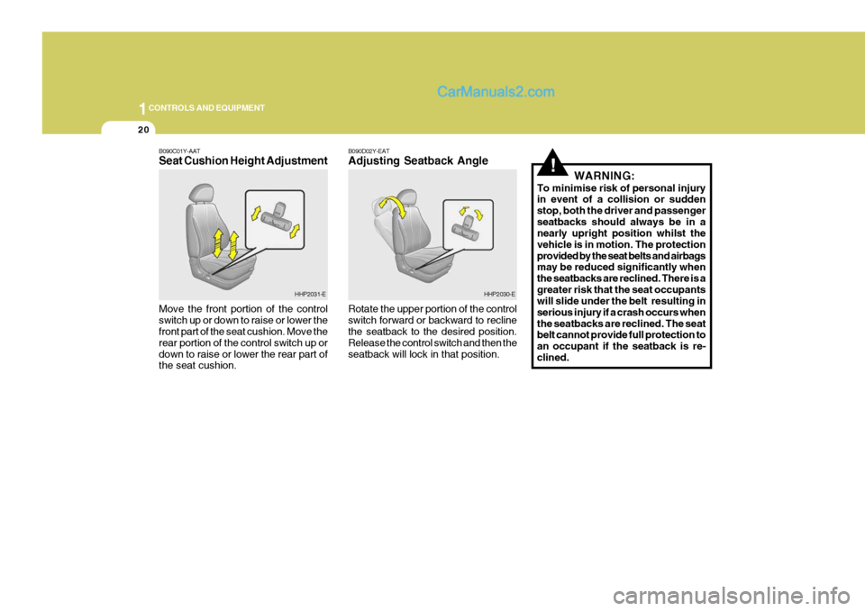
B090C01Y-AAT Seat Cushion Height Adjustment Move the front portion of the control switch up or down to raise or lower the front part of the seat cushion. Move the rear portion of the control switch up ordown to raise or lower the rear part of the seat cushion. B090D02Y-EAT Adjusting Seatback Angle Rotate the upper portion of the control switch forward or backward to recline the seatback to the desired position. Release the control switch and then theseatback will lock in that position.
WARNING:
To minimise risk of personal injury in event of a collision or sudden stop, both the driver and passengerseatbacks should always be in a nearly upright position whilst the vehicle is in motion. The protectionprovided by the seat belts and airbags may be reduced significantly when the seatbacks are reclined. There is agreater risk that the seat occupants will slide under the belt resulting in serious injury if a crash occurs whenthe seatbacks are reclined. The seat belt cannot provide full protection to an occupant if the seatback is re-clined.
HHP2031-EHHP2030-E
Page 511 of 539
6
OWNER MAINTENANCE
33
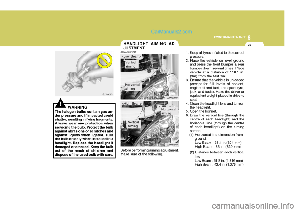
Before performing aiming adjustment, make sure of the following.HEADLIGHT AIMING AD- JUSTMENT
G290A01HP-EAT
1. Keep all tyres inflated to the correct
pressure.
2. Place the vehicle on level ground and press the front bumper & rear bumper down several times. Placevehicle at a distance of 118.1 in. (3m) from the test wall.
3. Ensure that the vehicle is unloaded (except for full levels of coolant, engine oil and fuel, and spare tyre,jack, and tools). Have the driver or equivalent weight placed in driver's seat.
4. Clean the headlight lens and turn on the headlight.
5. Open the bonnet.
6. Draw the vertical line (through the centre of each headlight) and thehorizontal line (through the centre of each headlight) on the aiming screen.
(1) Horizontal line dimension from
Horizontal aiming
Vertical aiming
G290B01HP
G290B02HP
Horizontal aiming
Vertical aiming
ground :Low Beam : 35.1 in.(894 mm) High Beam : 33 in. (839 mm)
(2) Distance between each vertical line :Low Beam : 51.8 in. (1,316 mm) High Beam : 42.4 in. (1,076 mm)
!WARNING:
The halogen bulbs contain gas un-
der pressure and if impacted could shatter, resulting in flying fragments.Always wear eye protection when servicing the bulb. Protect the bulb against abrasions or scratches andagainst liquids when lighted. Turn the bulb on only when installed in a headlight. Replace the headlight ifdamaged or cracked. Keep the bulb out of the reach of children and dispose of the used bulb with care. G270A03O
Page 536 of 539
10
INDEX
3
Coolant temperature gauge .....................................1-57
If the engine overheats ............................................. 3-4
Number ..................................................................... 8-2
Oil ............................................................................. 6-4 Starting ..................................................................... 2-5
Engine Exhaust Can Be Dangerous! ........................... 2-2
Exhaust Gas Warning .................................................. 7-2
F Fan Speed Control ................. .........................1-91, 1-102
Fog Light Switch
Front ....................................................................... 1-62
Rear ........................................................................ 1-62
Four-Wheel Drive(4WD) ............................................. 2-14
Front Door Edge Warning Light ................................. 1-85
Front Seats Adjustable head restraints ...................................... 1-17
Adjusting seatback angle ....................................... 1-17
Driver's seat lumbar support control .......................1-18
Seat adjust ment ..................................................... 1-16
Seat cushion height adjustment ............................. 1-19
Seat fore/aft adjustment ......................................... 1-16
Fuel
Capacity ................................................................... 9-2
Gauge ..................................................................... 1-57
Recommendations .................................................... 1-2
Fuel-Filler Flap
Remote release ...................................................... 1-82
Full-time 4WD Operation ............................................ 2-17
Fusible Links ............................................................. 6-25G
Glove Box ................................................................. 1-73
H Hatchback Door ......................................................... 1-78
Hazard Warning System ............................................ 1-65
Headlight Aiming Adjustment..................................... 6-33
Headlight Bulbs Replacement ....................................6-31
Headlight Leveling Device S ystem ............................1-86
Heated Front/Rear Window .. ......................................1-65
Heating and Cooling Control ......................................1-90
Heating and Ventilation
Air flow control ............................................. 1-92, 1-103
Air intake control ......................................... 1-92, 1-102
Defrosting/Defogging ............................................... 1-96
Fan speed control ........................................ 1-91, 1-102
Temperature control ................................................ 1-94
High-Mounted Rear Stop Light ...................................1-82
Horn ........................................................................... 1-85
I Ignition Switch ............................................................. 2-4
Illuminated ignition switch ......................................... 1-8
Immobiliser System ..................................................... 1-5
Indicator and Warning Lights ..................................... 1-50
Instrument Cluster and Indicator Lights ..................... 1-46
Interior Light ............................................................... 1-72
Interior Rearview Mirror .............................................. 1-77
Intermittent Wi pe Facility ........................................... 1-64