diagram INFINITI FX35 2004 Manual Online
[x] Cancel search | Manufacturer: INFINITI, Model Year: 2004, Model line: FX35, Model: INFINITI FX35 2004Pages: 4449, PDF Size: 99.66 MB
Page 1280 of 4449
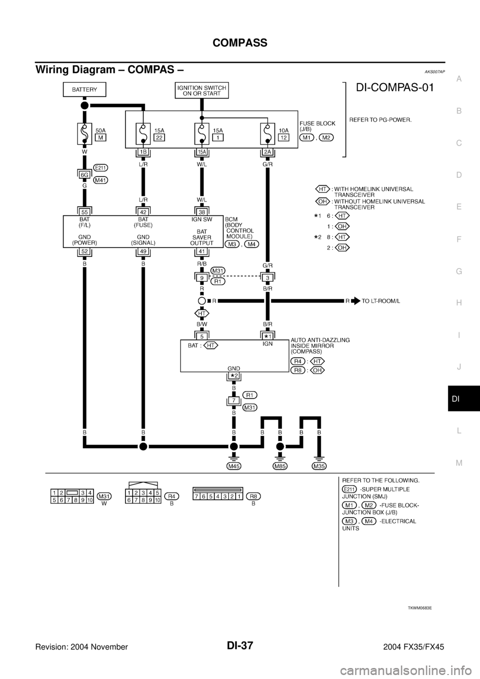
COMPASS
DI-37
C
D
E
F
G
H
I
J
L
MA
B
DI
Revision: 2004 November 2004 FX35/FX45
Wiring Diagram – COMPAS –AKS007AP
TKWM0683E
Page 1283 of 4449
DI-40
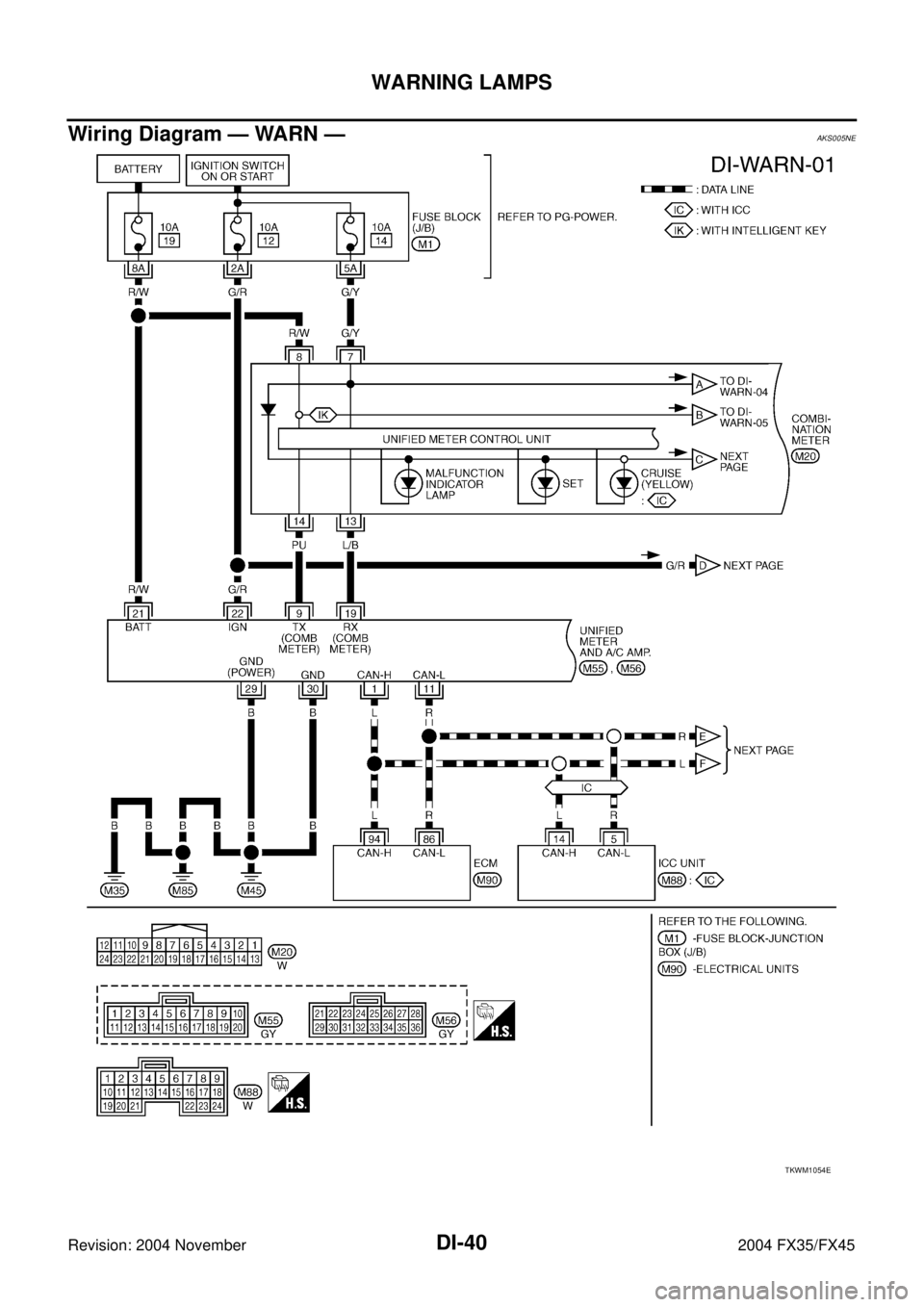
WARNING LAMPS
Revision: 2004 November 2004 FX35/FX45
Wiring Diagram — WARN —AKS005NE
TKWM1054E
Page 1294 of 4449
A/T INDICATOR
DI-51
C
D
E
F
G
H
I
J
L
MA
B
DI
Revision: 2004 November 2004 FX35/FX45
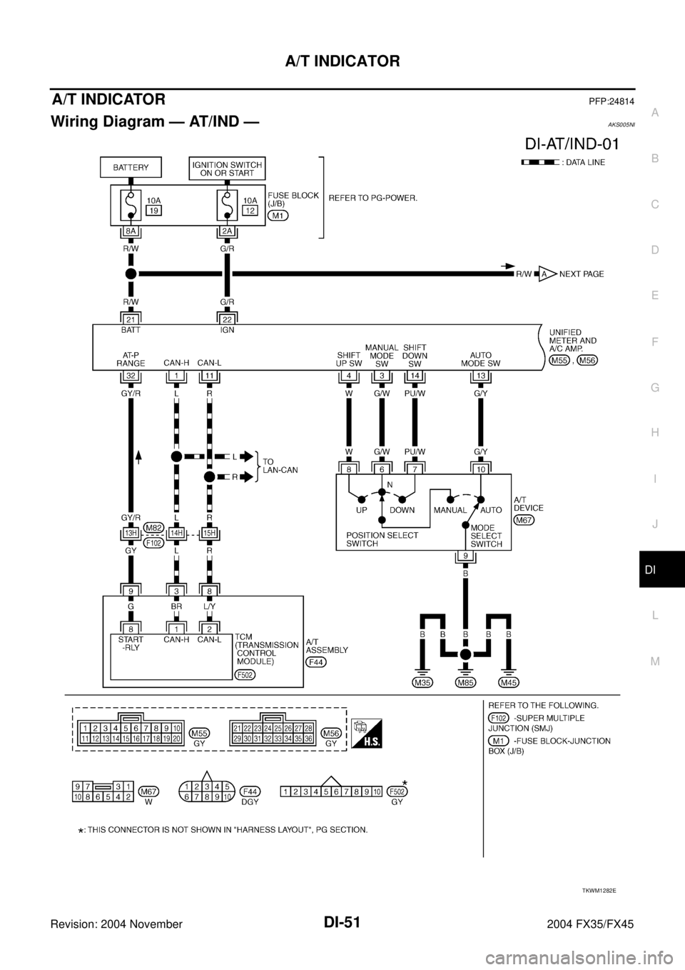
A/T INDICATORPFP:24814
Wiring Diagram — AT/IND —AKS005NI
TKWM1282E
Page 1302 of 4449
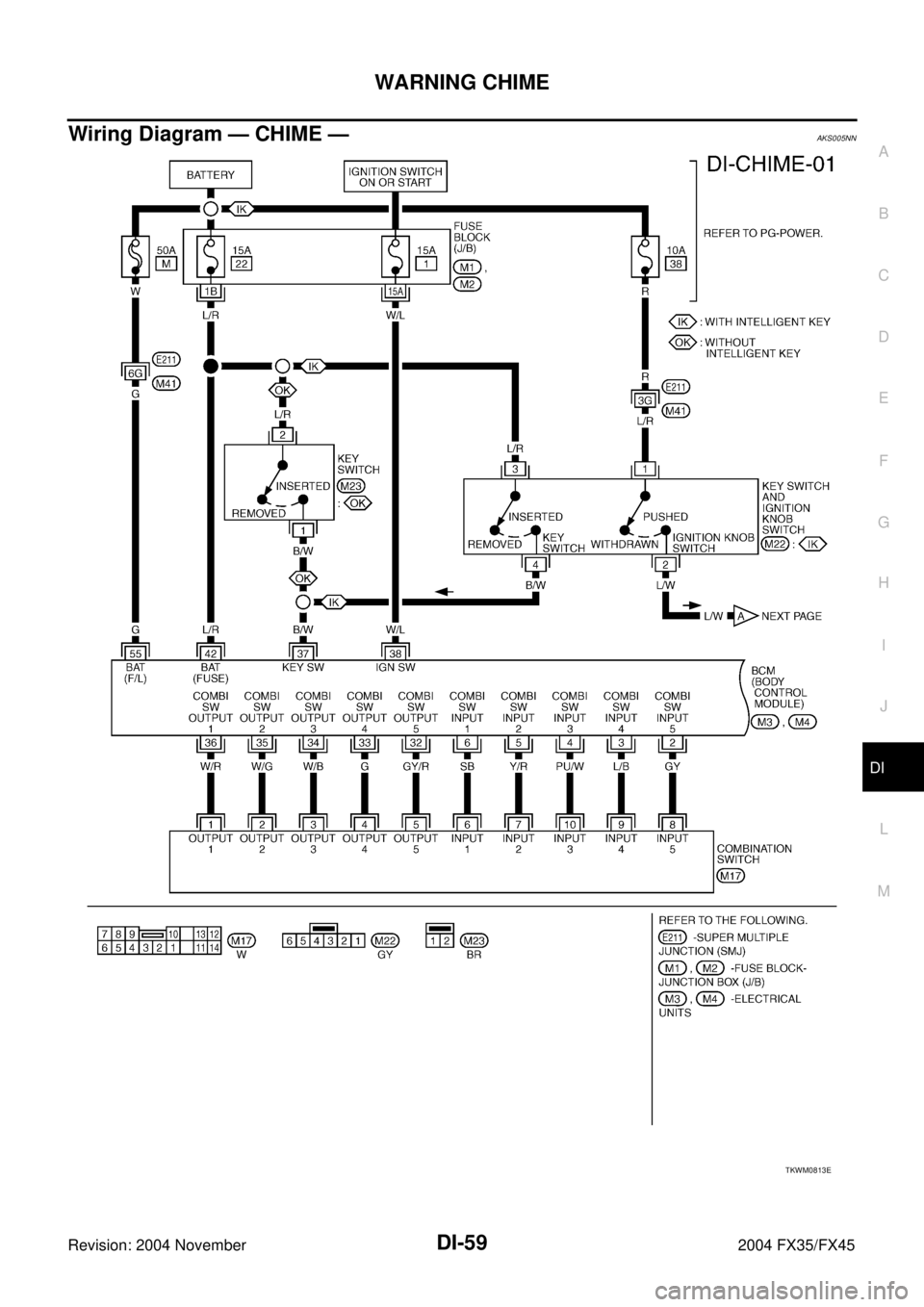
WARNING CHIME
DI-59
C
D
E
F
G
H
I
J
L
MA
B
DI
Revision: 2004 November 2004 FX35/FX45
Wiring Diagram — CHIME —AKS005NN
TKWM0813E
Page 1308 of 4449

WARNING CHIME
DI-65
C
D
E
F
G
H
I
J
L
MA
B
DI
Revision: 2004 November 2004 FX35/FX45
Preliminary CheckAKS005NS
CHECK POWER SUPPLY AND GROUND CIRCUIT
1. CHECK FUSE AND FUSIBLE LINK
Check BCM fuses and fusible link for blown-out.
Refer to DI-59, "Wiring Diagram — CHIME —" .
OK or NG
OK >> GO TO 2.
NG >> If fuse or fusible link is blown, be sure to eliminate cause of malfunction before installing new fuse
or fusible link. Refer to PG-3, "
POWER SUPPLY ROUTING CIRCUIT" .
2. CHECK POWER SUPPLY CIRCUIT
1. Disconnect BCM connector.
2. Check voltage between BCM harness connector terminals and
ground.
OK or NG
OK >> GO TO 3.
NG >> Check harness for open between BCM and fuse or fusible link.
3. CHECK GROUND CIRCUIT
1. Turn ignition switch OFF.
2. Check continuity between BCM harness connector M4 terminals
49 (B), 52 (B) and ground.
OK or NG
OK >> INSPECTION END
NG >> Repair harness or connector.
Unit Power source Fuse and fusible link No.
BCMBatteryM
22
Ignition switch ON or START 1
Terminals Ignition switch position
(+)
(–) OFF ACC ON
ConnectorTerminal
(Wire color)
M455 (G)
GroundBattery
voltageBattery
voltageBattery
voltage
42 (L/R)Battery
voltageBattery
voltageBattery
voltage
M3 38 (W/L) 0V 0VBattery
voltage
Continuity should exist.
SKIA5041E
Page 1315 of 4449

DI-72
WARNING CHIME
Revision: 2004 November 2004 FX35/FX45
5. CHECK KEY SWITCH CIRCUIT
1. Disconnect BCM connector.
2. Check continuity between BCM harness connector M3 terminal
37 (B/W) and key switch harness connector M23 terminal 1 (B/
W).
3. Check continuity between BCM harness connector M3 terminal
37 (B/W) and ground.
OK or NG
OK >> GO TO 6.
NG >> Repair harness or connector.
6. CHECK KEY SWITCH POWER SUPPLY CIRCUIT
Check voltage between key switch harness connector M23 terminal
2 (L/R) and ground.
OK or NG
OK >> Replace BCM. Refer to BCS-15, "Removal and Installa-
tion of BCM" .
NG >> Check harness for open or short between key switch
and fuse.
Key Warning Chime Does Not Operate (With Intelligent Key, When Mechanical
Key Is Used)
AKS0079U
1. CHECK FUSE
Check if the key switch and ignition knob switch 10A fuse (No. 38, located in the fuse and fusible link box) is
blown. Refer to DI-59, "
Wiring Diagram — CHIME —" .
Is the fuse blown?
YES >> Replace fuse. Be sure to repair the cause of malfunction before installing new fuse.
NO >> GO TO 2.
2. CHECK WARNING CHIME OPERATION
Check the chime under conditions in exception of key warning chime (when mechanical key is used) opera-
tion.
Does warning chime sound?
YES >> GO TO 3.
NO >> Go to DI-68, "
All Warnings Are Not Operated" or DI-69, "Key Warning Chime and Light Warning
Chime Does Not Operate (Seat Belt Warning Chime Does Operate)" . Continuity should exist.
Continuity should not exist.
SKIA5050E
Battery voltage should exist.
SKIA5051E
Page 1322 of 4449
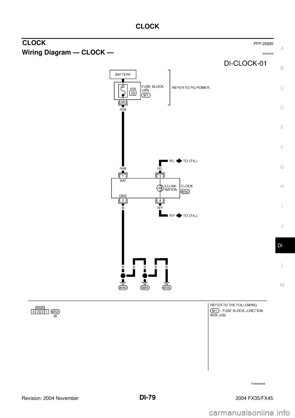
CLOCK
DI-79
C
D
E
F
G
H
I
J
L
MA
B
DI
Revision: 2004 November 2004 FX35/FX45
CLOCKPFP:25820
Wiring Diagram — CLOCK —AKS0056I
TKWM0699E
Page 1327 of 4449
DI-84
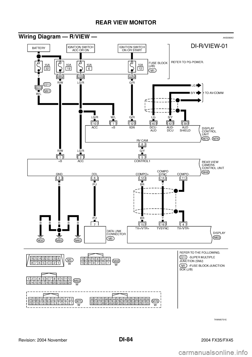
REAR VIEW MONITOR
Revision: 2004 November 2004 FX35/FX45
Wiring Diagram — R/VIEW —AKS0068G
TKWM0701E
Page 1342 of 4449

EC-1
ENGINE CONTROL SYSTEM
B ENGINE
CONTENTS
C
D
E
F
G
H
I
J
K
L
M
SECTION EC
A
EC
Revision: 2004 November 2004 FX35/FX45
ENGINE CONTROL SYSTEM
VQ35DE
INDEX FOR DTC ...................................................... 15
Alphabetical Index .................................................. 15
DTC No. Index ....................................................... 19
PRECAUTIONS ........................................................ 23
Precautions for Supplemental Restraint System
(SRS) “AIR BAG” and “SEAT BELT PRE-TEN-
SIONER” ................................................................ 23
On Board Diagnostic (OBD) System of Engine and
A/T .......................................................................... 23
Precaution .............................................................. 23
Wiring Diagrams and Trouble Diagnosis ................ 26
PREPARATION ......................................................... 27
Special Service Tools ............................................. 27
Commercial Service Tools ...................................... 28
ENGINE CONTROL SYSTEM .................................. 29
System Diagram ..................................................... 29
Vacuum Hose Drawing ........................................... 30
System Chart ......................................................... 31
Multiport Fuel Injection (MFI) System .................... 32
Electronic Ignition (EI) System ............................... 34
Air Conditioning Cut Control ................................... 35
Fuel Cut Control (at No Load and High Engine
Speed) .................................................................... 35
CAN communication .............................................. 36
BASIC SERVICE PROCEDURE .............................. 37
Idle Speed and Ignition Timing Check .................... 37
Idle Speed/Ignition Timing/Idle Mixture Ratio
Adjustment ............................................................. 38
Accelerator Pedal Released Position Learning ...... 49
Throttle Valve Closed Position Learning ................ 49
Idle Air Volume Learning ........................................ 49
Fuel Pressure Check .............................................. 51
ON BOARD DIAGNOSTIC (OBD) SYSTEM ............ 53
Introduction ............................................................ 53
Two Trip Detection Logic ........................................ 53
Emission-Related Diagnostic Information .............. 54
IVIS (Infiniti Vehicle Immobilizer System — NATS) ... 68
Malfunction Indicator Lamp (MIL) ........................... 68
OBD System Operation Chart ................................ 72TROUBLE DIAGNOSIS ............................................ 77
Trouble Diagnosis Introduction ............................... 77
DTC Inspection Priority Chart ................................. 80
Fail-Safe Chart ....................................................... 82
Basic Inspection ..................................................... 83
Symptom Matrix Chart ............................................ 88
Engine Control Component Parts Location ............ 92
Circuit Diagram ....................................................... 98
ECM Harness Connector Terminal Layout ...........100
ECM Terminals and Reference Value ...................100
CONSULT-II Function ...........................................109
Generic Scan Tool (GST) Function .......................122
CONSULT-II Reference Value in Data Monitor .....125
Major Sensor Reference Graph in Data Monitor
Mode .....................................................................129
TROUBLE DIAGNOSIS - SPECIFICATION VALUE .131
Description ............................................................131
Testing Condition ..................................................131
Inspection Procedure ............................................131
Diagnostic Procedure ...........................................132
TROUBLE DIAGNOSIS FOR INTERMITTENT INCI-
DENT .......................................................................135
Description ............................................................135
Diagnostic Procedure ...........................................135
POWER SUPPLY AND GROUND CIRCUIT ...........136
Wiring Diagram .....................................................136
Diagnostic Procedure ...........................................137
Ground Inspection ................................................141
DTC U1000, U1001 CAN COMMUNICATION LINE .142
Description ............................................................142
On Board Diagnosis Logic ....................................142
DTC Confirmation Procedure ...............................142
Wiring Diagram .....................................................143
Diagnostic Procedure ...........................................144
DTC P0011, P0021 IVT CONTROL ........................145
Description ............................................................145
CONSULT-II Reference Value in Data Monitor Mode
.145
On Board Diagnosis Logic ....................................146
Page 1343 of 4449

EC-2Revision: 2004 November 2004 FX35/FX45DTC Confirmation Procedure ...............................146
Diagnostic Procedure ...........................................148
DTC P0031, P0032, P0051, P0052 HO2S1 HEATER .149
Description ............................................................149
CONSULT-II Reference Value in Data Monitor Mode
.149
On Board Diagnosis Logic ....................................149
DTC Confirmation Procedure ...............................150
Wiring Diagram .....................................................151
Diagnostic Procedure ...........................................154
Component Inspection ..........................................156
Removal and Installation ......................................156
DTC P0037, P0038, P0057, P0058 HO2S2 HEATER .157
Description ............................................................157
CONSULT-II Reference Value in Data Monitor Mode
.157
On Board Diagnosis Logic ....................................157
DTC Confirmation Procedure ...............................158
Wiring Diagram .....................................................159
Diagnostic Procedure ...........................................162
Component Inspection ..........................................164
Removal and Installation ......................................164
DTC P0101 MAF SENSOR .....................................165
Component Description ........................................165
CONSULT-II Reference Value in Data Monitor Mode
.165
On Board Diagnosis Logic ....................................165
DTC Confirmation Procedure ...............................166
Overall Function Check ........................................167
Wiring Diagram .....................................................168
Diagnostic Procedure ...........................................169
Component Inspection ..........................................172
Removal and Installation ......................................172
DTC P0102, P0103 MAF SENSOR .........................173
Component Description ........................................173
CONSULT-II Reference Value in Data Monitor Mode
.173
On Board Diagnosis Logic ....................................173
DTC Confirmation Procedure ...............................174
Wiring Diagram .....................................................175
Diagnostic Procedure ...........................................176
Component Inspection ..........................................179
Removal and Installation ......................................179
DTC P0112, P0113 IAT SENSOR ...........................180
Component Description ........................................180
On Board Diagnosis Logic ....................................180
DTC Confirmation Procedure ...............................180
Wiring Diagram .....................................................182
Diagnostic Procedure ...........................................183
Component Inspection ..........................................184
Removal and Installation ......................................184
DTC P0117, P0118 ECT SENSOR ..........................185
Component Description ........................................185
On Board Diagnosis Logic ....................................185
DTC Confirmation Procedure ...............................186
Wiring Diagram .....................................................187
Diagnostic Procedure ...........................................188
Component Inspection ..........................................189
Removal and Installation ......................................189DTC P0122, P0123 TP SENSOR ............................190
Component Description ........................................190
CONSULT-II Reference Value in Data Monitor Mode
.190
On Board Diagnosis Logic ....................................190
DTC Confirmation Procedure ................................191
Wiring Diagram .....................................................192
Diagnostic Procedure ............................................193
Component Inspection ..........................................196
Removal and Installation .......................................196
DTC P0125 ECT SENSOR ......................................197
Component Description ........................................197
On Board Diagnosis Logic ....................................197
DTC Confirmation Procedure ................................198
Diagnostic Procedure ............................................198
Component Inspection ..........................................199
Removal and Installation .......................................199
DTC P0127 IAT SENSOR ........................................200
Component Description ........................................200
On Board Diagnosis Logic ....................................200
DTC Confirmation Procedure ................................200
Diagnostic Procedure ............................................201
Component Inspection ..........................................202
Removal and Installation .......................................202
DTC P0128 THERMOSTAT FUNCTION .................203
On Board Diagnosis Logic ....................................203
DTC Confirmation Procedure ................................203
Diagnostic Procedure ............................................203
Component Inspection ..........................................204
Removal and Installation .......................................204
DTC P0132, P0152 HO2S1 .....................................205
Component Description ........................................205
CONSULT-II Reference Value in Data Monitor Mode
.205
On Board Diagnosis Logic ....................................205
DTC Confirmation Procedure ................................206
Wiring Diagram .....................................................207
Diagnostic Procedure ............................................210
Component Inspection ..........................................212
Removal and Installation .......................................213
DTC P0133, P0153 HO2S1 .....................................214
Component Description ........................................214
CONSULT-II Reference Value in Data Monitor Mode
.214
On Board Diagnosis Logic ....................................214
DTC Confirmation Procedure ................................215
Overall Function Check .........................................216
Wiring Diagram .....................................................217
Diagnostic Procedure ............................................220
Component Inspection ..........................................224
Removal and Installation .......................................225
DTC P0134, P0154 HO2S1 .....................................226
Component Description ........................................226
CONSULT-II Reference Value in Data Monitor Mode
.226
On Board Diagnosis Logic ....................................226
DTC Confirmation Procedure ................................227
Overall Function Check .........................................228
Wiring Diagram .....................................................229