installation INFINITI FX35 2008 Service Manual
[x] Cancel search | Manufacturer: INFINITI, Model Year: 2008, Model line: FX35, Model: INFINITI FX35 2008Pages: 3924, PDF Size: 81.37 MB
Page 881 of 3924

BACK DOOR LOCK ASSEMBLYBL-147
< SERVICE INFORMATION >
C
DE
F
G H
J
K L
M A
B
BL
N
O P
Through hole is as shown in the figure.
5. Disconnect back door opener switch harness connector (and rear view camera if equipped).
6. Remove opener switch from back door through hole.
INSTALLATION
Install in the reverse order of removal.
CAUTION:
After installing, check operation.
Disassembly and AssemblyINFOID:0000000001327887
BACK DOOR LOCK & CLOSURE ASSEMBLY
CAUTION:
Be sure to remove or install the back door clos ure motor with the back door lock & closure assembly.
1. Remove the back door closure motor.
PIIB1645E
PIIB1647E
PIIA6080E
3AA93ABC3ACD3AC03ACA3AC03AC63AC53A913A773A893A873A873A8E3A773A983AC73AC93AC03AC3
3A893A873A873A8F3A773A9D3AAF3A8A3A8C3A863A9D3AAF3A8B3A8C
Page 896 of 3924

BL-162
< SERVICE INFORMATION >
BACK DOOR AUTO CLOSURE SYSTEM
2.CHECK HARNESS CONTINUITY
1. Disconnect back door closure control uni t and back door closure motor connector.
2. Check continuity between back door closure control unit con-
nector D106 terminals 2, 3 and back door closure motor connec-
tor D109 terminals 1, 2.
3. Check continuity between back door closure control unit con- nector D106 terminals 2, 3 and ground.
OK or NG
OK >> Replace back door closure motor.
NG >> Repair or replace harness.
Removal and Installation of Back Door Closer Control UnitINFOID:0000000001327903
1. Remove the back door finisher. EI-47, "Component Parts Location".
2. Disconnect the back door closer control unit harness, remove the screw and back door closer control unit.
2 (PU) – 1 (PU) : Cont
inuity should exist.
3 (G) – 2 (G) : Conti nuity should exist.
2 (PU) – Ground : Continuity should not exist.
3 (G) – Ground : Continuity should not exist.
PIIA6186E
3AA93ABC3ACD3AC03ACA3AC03AC63AC53A913A773A893A873A873A8E3A773A983AC73AC93AC03AC3
3A893A873A873A8F3A773A9D3AAF3A8A3A8C3A863A9D3AAF3A8B3A8C
Page 914 of 3924

BL-180
< SERVICE INFORMATION >
VEHICLE SECURITY (THEFT WARNING) SYSTEM
4.CHECK BCM OUTPUT SIGNAL
1. Connect BCM connector.
2. Check voltage between BCM connector M3, B14 terminals 12, 13, 62, 63 and ground.
OK or NG
OK >> Check condition of harness and connector.
NG >> Replace BCM.
1 – 2 HOOD SWITCH CHECK
1.CHECK HOOD SWITCH
Check hood switch and hood fitting condition.
OK or NG
OK >> GO TO 2.
NG >> Adjust installation of hood switch.
2.CHECK HOOD SWITCH INPUT SIGNAL
With CONSULT-III
Check (“HOOD SW”) in “DATA MONITOR” mode with CONSULT-III.
Without CONSULT-III
Check voltage between IPDM E/R connector and ground.
OK or NG
OK >> Hood switch is OK, and go to “1 – 3 BACK DOOR SWITCH CHECK”.
NG >> GO TO 3.
3.CHECK HOOD SWITCH
1. Turn ignition switch OFF.
2. Disconnect hood switch connector. 12 (P/B) – Ground : Battery voltage
13 (P/L) – Ground : Battery voltage
62 (W) – Ground : Battery voltage
63 (P) – Ground : Battery voltage
PIIA6223E
Monitor item Condition
HOOD SW OPEN : ON
CLOSE : OFF
Connector Terminals (Wire color)
ConditionVoltage (V)
(Approx.)
(+) (-)
E9 56 (LG) Ground OPEN 0
CLOSE Battery voltage
PIIA6228E
3AA93ABC3ACD3AC03ACA3AC03AC63AC53A913A773A893A873A873A8E3A773A983AC73AC93AC03AC3
3A893A873A873A8F3A773A9D3AAF3A8A3A8C3A863A9D3AAF3A8B3A8C
Page 932 of 3924

BL-198
< SERVICE INFORMATION >
IVIS (INFINITI VEHICLE IMMOBILIZER SYSTEM-NATS)
“LOCK MODE” displayed on CONSULT-III screen
1.CONFIRM SELF-DIAGNOSTIC RESULTS
Confirm SELF-DIAGNOSTIC RESULTS “LOCK MO DE” is displayed on CONSULT-III screen.
Does CONSULT-III screen disp lay as shown in figure?
YES >> GO TO 2.
NO >> Refer to BL-195, "
Trouble Diagnosis Symptom Chart".
2.ESCAPE FROM LOCK MODE
1. Turn ignition switch OFF.
2. Turn ignition switch ON with registered key. (Do not start engine.) Wait 5 seconds.
3. Return the key to OFF position. Wait 5 seconds.
4. Repeat steps 2 and 3 twice (total of three cycles).
5. Start the engine.
Does engine start?
YES >> System is OK (Now system is escaped from “LOCK MODE”).
NO >> GO TO 3.
3.PERFORM INITIALIZATION WITH CONSULT-III
Perform initialization with CONSULT-III.
For initialization, refer to “CONSULT -III Operation Manual NATS-IVIS/NVIS”.
NOTE:
If the initialization is not completed or malf unction, CONSULT-III shows the message on the screen.
Can the system be initialized?
YES >> System is OK.
NO >> GO TO 4.
4.PERFORM INITIALIZATION WITH CONSULT-III AGAIN
1. Replace BCM.
2. Perform initialization with CONSULT-III. For initialization, refer to “CONSULT -III Operation Manual NATS-IVIS/NVIS”.
NOTE:
If the initialization is not completed or malf unctions, CONSULT-III shows the message on the screen.
Can the system be initialized?
YES >> System is OK. BCM is malfunctioning. Replace BCM.
Perform initialization with CONSULT-III.
For initialization, refer to “CONSULT -III Operation Manual NATS-IVIS/NVIS”.
NO >> ECM is malfunctioning. Replace ECM.
Perform initialization or re-communicating function.
- For initialization, refer to “CONSULT -III Operation Manual NATS-IVIS/NVIS”.
- For re-communicating function, refer to BL-187, "
ECM Re-Communicating Function".
Diagnosis Procedure 5INFOID:0000000001327938
Self-diagnostic results:
“CHAIN OF IMMU-KEY” is displayed on CONSULT-III screen
1.CONFIRM SELF-DIAGNOSTIC RESULTS
Confirm self-diagnostic results “CHAIN OF IM MU-KEY” is displayed on CONSULT-III screen.
Does CONSULT-III screen display as shown?
YES >> GO TO 2.
NO >> Refer to BL-195, "
Trouble Diagnosis Symptom Chart".
2.CHECK NATS ANTENNA AMP. INSTALLATION
Check NATS antenna amp. installation. Refer to BL-201, "
Removal and Installation NATS Antenna Amp".
OK or NG
OK >> GO TO 3.
3AA93ABC3ACD3AC03ACA3AC03AC63AC53A913A773A893A873A873A8E3A773A983AC73AC93AC03AC3
3A893A873A873A8F3A773A9D3AAF3A8A3A8C3A863A9D3AAF3A8B3A8C
Page 935 of 3924

IVIS (INFINITI VEHICLE IMMOBILIZER SYSTEM-NATS)
BL-201
< SERVICE INFORMATION >
C
D E
F
G H
J
K L
M A
B
BL
N
O P
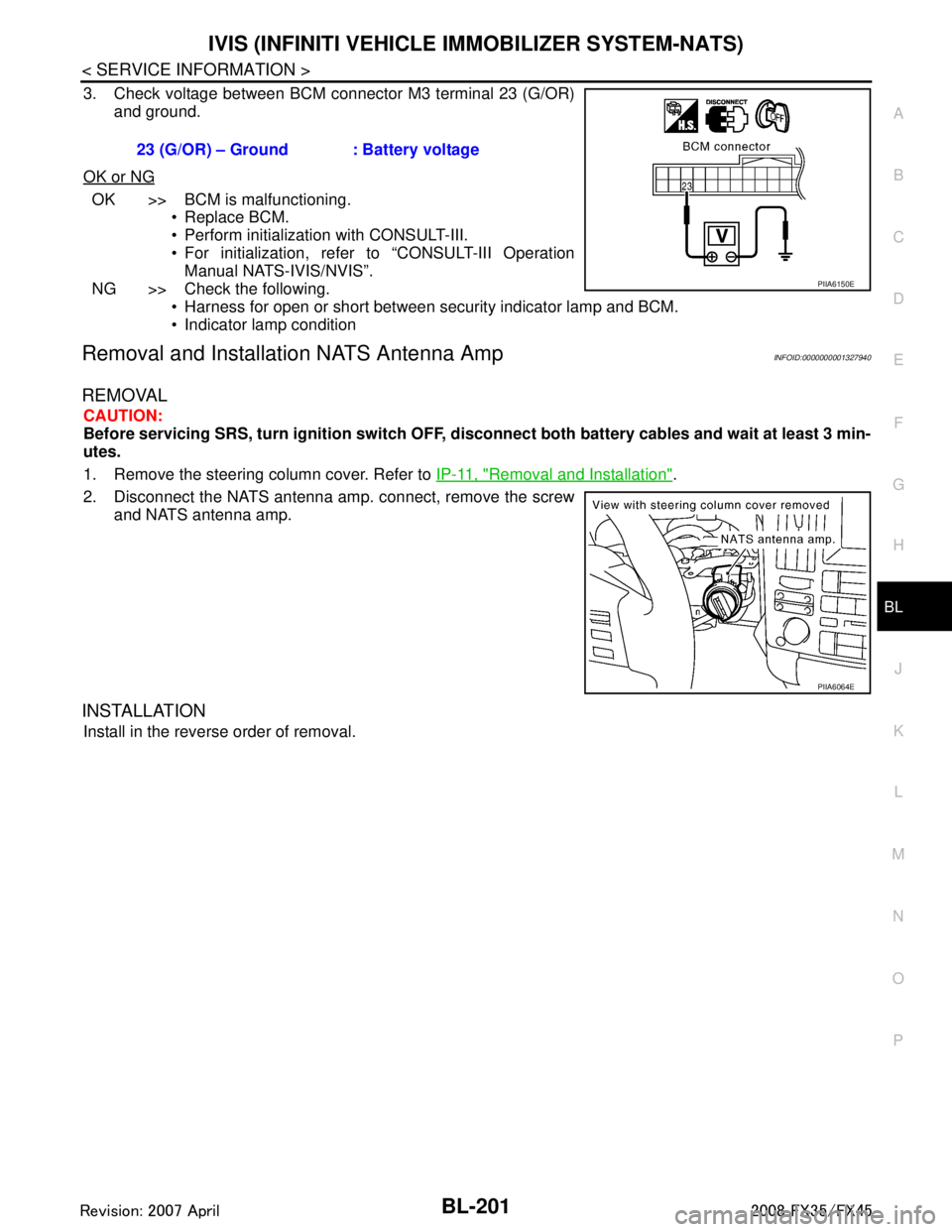
3. Check voltage between BCM connector M3 terminal 23 (G/OR) and ground.
OK or NG
OK >> BCM is malfunctioning. Replace BCM.
Perform initialization with CONSULT-III.
For initialization, refer to “CONSULT-III OperationManual NATS-IVIS/NVIS”.
NG >> Check the following. Harness for open or short between security indicator lamp and BCM.
Indicator lamp condition
Removal and Installa tion NATS Antenna AmpINFOID:0000000001327940
REMOVAL
CAUTION:
Before servicing SRS, turn ignition switch OFF, disconnect both battery cables and wait at least 3 min-
utes.
1. Remove the steering column cover. Refer to IP-11, "
Removal and Installation".
2. Disconnect the NATS antenna amp. connect, remove the screw and NATS antenna amp.
INSTALLATION
Install in the reverse order of removal. 23 (G/OR) – Ground : Battery voltage
PIIA6150E
PIIA6064E
3AA93ABC3ACD3AC03ACA3AC03AC63AC53A913A773A893A873A873A8E3A773A983AC73AC93AC03AC3
3A893A873A873A8F3A773A9D3AAF3A8A3A8C3A863A9D3AAF3A8B3A8C
Page 985 of 3924

BR-1
BRAKES
C
DE
G H
I
J
K L
M
SECTION BR
A
B
BR
N
O P
CONTENTS
BRAKE SYSTEM
SERVICE INFORMATION .. ..........................2
PRECAUTIONS .............................................. .....2
Precaution for Supplemental Restraint System
(SRS) "AIR BAG" and "SEAT BELT PRE-TEN-
SIONER" ............................................................. ......
2
Precaution for Procedure without Cowl Top Cover ......2
Precaution for Brake System ....................................2
PREPARATION ...................................................3
Commercial Service Tool .................................... ......3
NOISE, VIBRATION AND HARSHNESS
(NVH) TROUBLESHOOTING .............................
4
NVH Troubleshooting Chart ................................ ......4
BRAKE PEDAL .............................................. .....5
Inspection and Adjustment .................................. ......5
Component ................................................................6
Removal and Installation ...........................................6
BRAKE FLUID .....................................................8
On-Board Inspection ........................................... ......8
Drain and Refill ..........................................................8
Bleeding Brake System .............................................8
BRAKE TUBE AND HOSE ................................10
Hydraulic Circuit .................................................. ....10
Removal and Installation of Front Brake Tube and
Brake Hose .............................................................
10
Removal and Installation of Rear Brake Piping
and Brake Hose ......................................................
11
Inspection After Installation .....................................11
BRAKE MASTER CYLINDER ........................ ....12
On-Board Inspection ........................................... ....12
Component ..............................................................12
Removal and Installation .........................................12
Disassembly and Assembly ....................................13
BRAKE BOOSTER ...........................................14
On-Vehicle Service .............................................. ....14
Component ..............................................................14
Removal and Installation .........................................14
VACUUM LINES ...............................................16
Component ..............................................................16
Removal and Installation .........................................16
Inspection ................................................................16
FRONT DISC BRAKE .......................................18
On-Vehicle Inspection ......................................... ....18
Component ..............................................................18
Removal and Installation of Brake Pad ...................19
Removal and Installation of Brake Caliper Assem-
bly ........................................................................ ....
19
Disassembly and Assembly of Brake Caliper As-
sembly .....................................................................
20
Brake Burnishing Procedure ....................................23
REAR DISC BRAKE .........................................24
On-Vehicle Inspection ......................................... ....24
Component ..............................................................24
Removal and Installation of Brake Pad ...................25
Removal and Installation of Brake Caliper Assem-
bly ........................................................................ ....
25
Disassembly and Assembly of Brake Caliper As-
sembly .....................................................................
26
Brake Burnishing Procedure ....................................29
SERVICE DATA AND SPECIFICATIONS
(SDS) .................................................................
30
General Specification ..............................................30
Brake Pedal .............................................................30
Brake Booster ..........................................................30
Check Valve ............................................................30
Front Disc Brake ......................................................30
Rear Disc Brake ......................................................30
3AA93ABC3ACD3AC03ACA3AC03AC63AC53A913A773A893A873A873A8E3A773A983AC73AC93AC03AC3
3A893A873A873A8F3A773A9D3AAF3A8A3A8C3A863A9D3AAF3A8B3A8C
Page 986 of 3924

BR-2
< SERVICE INFORMATION >
PRECAUTIONS
SERVICE INFORMATION
PRECAUTIONS
Precaution for Supplemental Restraint System (SRS) "AIR BAG" and "SEAT BELT
PRE-TENSIONER"
INFOID:0000000001612918
The Supplemental Restraint System such as “A IR BAG” and “SEAT BELT PRE-TENSIONER”, used along
with a front seat belt, helps to reduce the risk or severi ty of injury to the driver and front passenger for certain
types of collision. This system includes seat belt switch inputs and dual stage front air bag modules. The SRS
system uses the seat belt switches to determine the front air bag deployment, and may only deploy one front
air bag, depending on the severity of a collision and w hether the front occupants are belted or unbelted.
Information necessary to service the system safely is included in the “SUPPLEMENTAL RESTRAINT SYS-
TEM” and “SEAT BELTS” of this Service Manual.
WARNING:
• To avoid rendering the SRS inopera tive, which could increase the risk of personal injury or death in
the event of a collision which would result in air bag inflation, all maintenance must be performed by
an authorized NISS AN/INFINITI dealer.
Improper maintenance, including in correct removal and installation of the SRS, can lead to personal
injury caused by unintent ional activation of the system. For re moval of Spiral Cable and Air Bag
Module, see the “SUPPLEMEN TAL RESTRAINT SYSTEM”.
Do not use electrical test equipmen t on any circuit related to the SRS unless instructed to in this
Service Manual. SRS wiring harnesses can be identi fied by yellow and/or orange harnesses or har-
ness connectors.
Precaution for Procedure without Cowl Top CoverINFOID:0000000001612920
When performing the procedure after removing cowl top cover, cover
the lower end of windshield with urethane, etc.
Precaution for Brake SystemINFOID:0000000001327604
Clean dust on front brake and rear brake with a vacuum dust collector. Do not blow with compressed air.
Recommended fluid is brake fluid “DOT 3”. MA-9, "
Fluids and Lubricants".
Do not reuse drained brake fluid.
Be careful not to splash brake fluid on painted areas.
To clean or wash all parts of master cylinder, disc brake caliper and wheel cylinder, use new brake fluid.
Do not use mineral oils such as gasoline or kerosene. They will ruin rubber parts of the hydraulic system.
Use a flare nut crowfoot and torque wrench when installing brake
tube.
When installing brake piping, be sure to check torque.
Before working, turn ignition switch OFF and disconnect connec- tors for ABS actuator and electric unit (control unit) or battery neg-
ative terminal.
Burnish the brake contact surfaces after refinishing or replacing drums or rotors, after replacing pads or linings, or if a soft pedal
occurs at very low mileage.
Refer to BR-23, "
Brake Burnishing Procedure" (Front disc brake),
BR-29, "
Brake Burnishing Procedure" (Rear disc brake).
WARNING:
Clean brake pads and shoes with a waste cl oth, then clean with a dust collector.
PIIB3706J
SBR686C
3AA93ABC3ACD3AC03ACA3AC03AC63AC53A913A773A893A873A873A8E3A773A983AC73AC93AC03AC3
3A893A873A873A8F3A773A9D3AAF3A8A3A8C3A863A9D3AAF3A8B3A8C
Page 990 of 3924

BR-6
< SERVICE INFORMATION >
BRAKE PEDAL
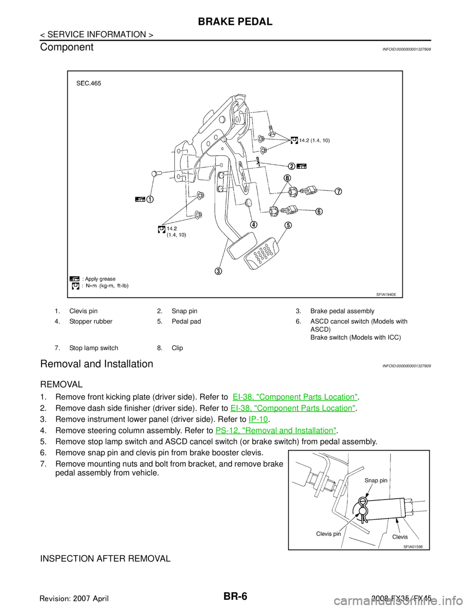
Component
INFOID:0000000001327608
Removal and InstallationINFOID:0000000001327609
REMOVAL
1. Remove front kicking plate (driver side). Refer to EI-38, "Component Parts Location".
2. Remove dash side finisher (driver side). Refer to EI-38, "
Component Parts Location".
3. Remove instrument lower panel (driver side). Refer to IP-10
.
4. Remove steering column assembly. Refer to PS-12, "
Removal and Installation".
5. Remove stop lamp switch and ASCD cancel s witch (or brake switch) from pedal assembly.
6. Remove snap pin and clevis pin from brake booster clevis.
7. Remove mounting nuts and bolt from bracket, and remove brake pedal assembly from vehicle.
INSPECTION AFTER REMOVAL
1. Clevis pin 2. Snap pin 3. Brake pedal assembly
4. Stopper rubber 5. Pedal pad 6. ASCD cancel switch (Models with
ASCD)
Brake switch (Models with ICC)
7. Stop lamp switch 8. Clip
SFIA1940E
SFIA0159E
3AA93ABC3ACD3AC03ACA3AC03AC63AC53A913A773A893A873A873A8E3A773A983AC73AC93AC03AC3
3A893A873A873A8F3A773A9D3AAF3A8A3A8C3A863A9D3AAF3A8B3A8C
Page 991 of 3924

BRAKE PEDALBR-7
< SERVICE INFORMATION >
C
DE
G H
I
J
K L
M A
B
BR
N
O P
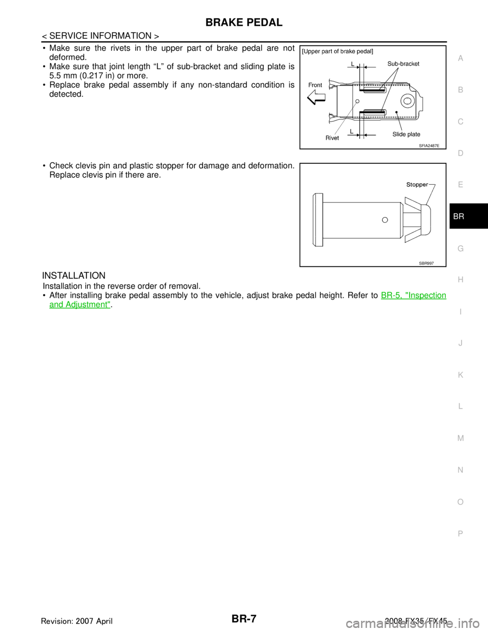
Make sure the rivets in the upper part of brake pedal are not deformed.
Make sure that joint length “L” of sub-bracket and sliding plate is
5.5 mm (0.217 in) or more.
Replace brake pedal assembly if any non-standard condition is detected.
Check clevis pin and plastic stopper for damage and deformation. Replace clevis pin if there are.
INSTALLATION
Installation in the reverse order of removal.
After installing brake pedal assembly to the vehicle, adjust brake pedal height. Refer to BR-5, "
Inspection
and Adjustment".
SFIA2487E
SBR997
3AA93ABC3ACD3AC03ACA3AC03AC63AC53A913A773A893A873A873A8E3A773A983AC73AC93AC03AC3
3A893A873A873A8F3A773A9D3AAF3A8A3A8C3A863A9D3AAF3A8B3A8C
Page 994 of 3924

BR-10
< SERVICE INFORMATION >
BRAKE TUBE AND HOSE
BRAKE TUBE AND HOSE
Hydraulic CircuitINFOID:0000000001327613
CAUTION:
All brake hoses and tubes must be free from excessive bending, twisting and pulling.
Make sure there is no interference with other part s when turning steering both clockwise and coun-
terclockwise.
The brake tubes and hoses is an important safety pa rt. If a brake fluid leak is detected, always disas-
semble the parts. Replace applicable part with a new one, if necessary.
Be careful not to splash brake fluid on painted areas; it way cause paint damage. If brake fluid is
splashed on painted surfaces of bo dy, immediately wipe it off and them wash it away with water
immediately.
Do not bend or twist brake hose sharply, or strongly pull it.
When removing components, cover br ake line connections so that no dirt, no dust, or other foreign
matter gets in.
Refill with new brake fluid “ DOT 3 ”.
Do not reuse drained brake fluid.
Removal and Installation of Fr ont Brake Tube and Brake HoseINFOID:0000000001327614
REMOVAL
1. Drain brake fluid. Refer to BR-8, "Drain and Refill".
2. Using a flare nut wrench, remove brake tube from brake hose.
3. Remove union bolt and remove brake hose from caliper assembly.
4. Remove lock plate and remove brake hose from vehicle.
INSTALLATION
1. Position brake hose by aligning with the protrusion on caliper assembly, and them tighten union bolt to the specified torque.
CAUTION:
Do not reuse copper washer.
2. Install brake hose to brake tube. Temporarily tighten flare nut by hand as much as possible. Secure them it to bracket with lock
plate.
3. Using a flare nut torque wrench, tighten flare nut to the specified
torque.
4. Refill brake fluid and bleed air. Refer to BR-8, "
Bleeding Brake
System".
PFIA0818E
SFIA1204E
3AA93ABC3ACD3AC03ACA3AC03AC63AC53A913A773A893A873A873A8E3A773A983AC73AC93AC03AC3
3A893A873A873A8F3A773A9D3AAF3A8A3A8C3A863A9D3AAF3A8B3A8C