tow INFINITI FX35 2008 User Guide
[x] Cancel search | Manufacturer: INFINITI, Model Year: 2008, Model line: FX35, Model: INFINITI FX35 2008Pages: 3924, PDF Size: 81.37 MB
Page 537 of 3924
ATC-132
< SERVICE INFORMATION >
REFRIGERANT LINES
Removal and Installation of High-pressu re Pipe 1 and 2 (Engine Compartment)
INFOID:0000000001328224
REMOVAL
1. Remove low-pressure pipe 1. Refer to ATC-131, "Removal and Installation of Low-Pressure Pipe 1
(Engine Compartment)".
2. Remove high-pressure flexible hose and low-pressure flexible hose. Refer to ATC-129, "
Removal and
Installation of High-pressure Flexible Hose" and ATC-128, "Removal and Installation of Low-Pressure
Flexible Hose".
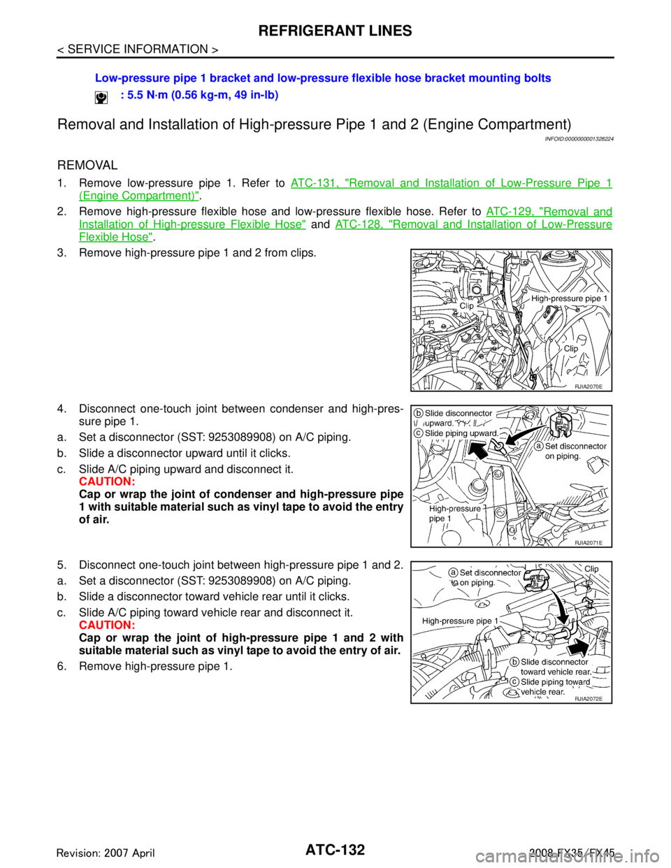
3. Remove high-pressure pipe 1 and 2 from clips.
4. Disconnect one-touch joint between condenser and high-pres- sure pipe 1.
a. Set a disconnector (SST: 9253089908) on A/C piping.
b. Slide a disconnector upward until it clicks.
c. Slide A/C piping upward and disconnect it. CAUTION:
Cap or wrap the joint of condenser and high-pressure pipe
1 with suitable material such as vinyl tape to avoid the entry
of air.
5. Disconnect one-touch joint between high-pressure pipe 1 and 2.
a. Set a disconnector (SST: 9253089908) on A/C piping.
b. Slide a disconnector toward vehicle rear until it clicks.
c. Slide A/C piping toward vehicle rear and disconnect it. CAUTION:
Cap or wrap the joint of hi gh-pressure pipe 1 and 2 with
suitable material such as vinyl tape to avoid the entry of air.
6. Remove high-pressure pipe 1. Low-pressure pipe 1 bracket and low-pressu
re flexible hose bracket mounting bolts
: 5.5 N·m (0.56 kg-m, 49 in-lb)
RJIA2070E
RJIA2071E
RJIA2072E
3AA93ABC3ACD3AC03ACA3AC03AC63AC53A913A773A893A873A873A8E3A773A983AC73AC93AC03AC3
3A893A873A873A8F3A773A9D3AAF3A8A3A8C3A863A9D3AAF3A8B3A8C
Page 538 of 3924
REFRIGERANT LINESATC-133
< SERVICE INFORMATION >
C
DE
F
G H
I
K L
M A
B
AT C
N
O P
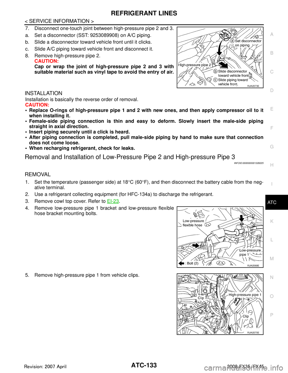
7. Disconnect one-touch joint between high-pressure pipe 2 and 3.
a. Set a disconnector (SST: 9253089908) on A/C piping.
b. Slide a disconnector toward vehicle front until it clicks.
c. Slide A/C piping toward vehicle front and disconnect it.
8. Remove high-pressure pipe 2. CAUTION:
Cap or wrap the joint of hi gh-pressure pipe 2 and 3 with
suitable material such as vinyl tape to avoid the entry of air.
INSTALLATION
Installation is basically the reverse order of removal.
CAUTION:
Replace O-rings of high-pressure pipe 1 and 2 wit h new ones, and then apply compressor oil to it
when installing it.
Female-side piping c onnection is thin and easy to deform. Slowly insert the male-side piping
straight in axial direction.
Insert piping securely until a click is heard.
After piping connection is comple ted, pull male-side piping by hand to make sure that connection
does not come loose.
When recharging refrigerant, check for leaks.
Removal and Installation of Low-Pressu re Pipe 2 and High-pressure Pipe 3
INFOID:0000000001328225
REMOVAL
1. Set the temperature (passenger side) at 18 °C (60 °F), and then disconnect the battery cable from the neg-
ative terminal.
2. Use a refrigerant collecting equipment (f or HFC-134a) to discharge the refrigerant.
3. Remove cowl top cover. Refer to EI-23
.
4. Remove low-pressure pipe 1 bracket and low-pressure flexible hose bracket mounting bolts.
5. Remove high-pressure pipe 1 from vehicle clips.
RJIA2073E
RJIA2068E
RJIA2070E
3AA93ABC3ACD3AC03ACA3AC03AC63AC53A913A773A893A873A873A8E3A773A983AC73AC93AC03AC3
3A893A873A873A8F3A773A9D3AAF3A8A3A8C3A863A9D3AAF3A8B3A8C
Page 539 of 3924
![INFINITI FX35 2008 User Guide
ATC-134
< SERVICE INFORMATION >
REFRIGERANT LINES
6. Disconnect one-touch joints.
a. Set a disconnector [high-pressure side (SST: 9253089908), low-pressure side (SST: 9253089916)] on A/C piping.
b. S INFINITI FX35 2008 User Guide
ATC-134
< SERVICE INFORMATION >
REFRIGERANT LINES
6. Disconnect one-touch joints.
a. Set a disconnector [high-pressure side (SST: 9253089908), low-pressure side (SST: 9253089916)] on A/C piping.
b. S](/img/42/57017/w960_57017-538.png)
ATC-134
< SERVICE INFORMATION >
REFRIGERANT LINES
6. Disconnect one-touch joints.
a. Set a disconnector [high-pressure side (SST: 9253089908), low-pressure side (SST: 9253089916)] on A/C piping.
b. Slide a disconnector toward vehicle front until it clicks.
c. Slide A/C piping toward vehicle front and disconnect it. CAUTION:
Cap or wrap the joint of low-pressure pipe 1 and high-pres-
sure pipe 2 with suitable material such as vinyl tape to
avoid the entry of air.
7. Remove blower unit. Refer to ATC-103
.
8. Remove mounting screws, and then remove air mix door motor (passenger side), mode door motor and evaporator cover.
9. Remove mounting bolt, and then remove low-pressure pipe 2 and high-pressure pipe 3.
CAUTION:
Cap or wrap the joint of expan sion valve with suitable mate-
rial such as vinyl tape to avoid the entry of air.
INSTALLATION
Installation is basically the reverse order of removal.
CAUTION:
Replace O-rings of low-pressure pipe 1, 2 and high-p ressure pipe 2, 3 with new ones, and then apply
compressor oil to it when installing it.
Female-side piping connection is thin and easy to deform. Slowly insert the male-side piping
straight in axial direction.
Insert piping securely until a click is heard.
After piping connection is comp leted, pull male-side piping by hand to make sure that connection
does not come loose.
When recharging refrigerant, check for leaks.
Removal and Installation of Liquid TankINFOID:0000000001328226
REMOVAL
1. Use a refrigerant collecting equipment (for HFC-134a) to discharge the refrigerant.
2. Remove front grille. Refer to EI-22
.
3. Clean liquid tank and its surrounding area, and remove dust and rust from liquid tank. CAUTION:
RJIA2037E
RJIA0940E
RJIA2038E
Low-pressure pipe 1 bracket and low-pressure flexible hose bracket mounting bolts
: 5.5 N·m (0.56 kg-m, 49 in-lb)
3AA93ABC3ACD3AC03ACA3AC03AC63AC53A913A773A893A873A873A8E3A773A983AC73AC93AC03AC3
3A893A873A873A8F3A773A9D3AAF3A8A3A8C3A863A9D3AAF3A8B3A8C
Page 750 of 3924
BL-16
< SERVICE INFORMATION >
HOOD
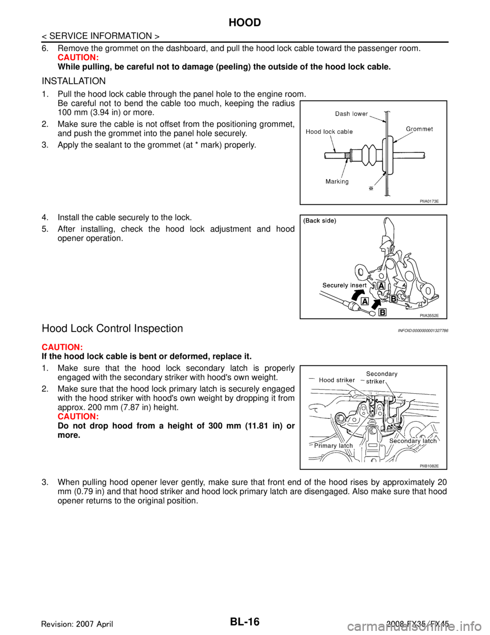
6. Remove the grommet on the dashboard, and pull the hood lock cable toward the passenger room.CAUTION:
While pulling, be careful not to damage (p eeling) the outside of the hood lock cable.
INSTALLATION
1. Pull the hood lock cable through the panel hole to the engine room.
Be careful not to bend the cable too much, keeping the radius
100 mm (3.94 in) or more.
2. Make sure the cable is not offset from the positioning grommet, and push the grommet into the panel hole securely.
3. Apply the sealant to the grommet (at * mark) properly.
4. Install the cable securely to the lock.
5. After installing, check the hood lock adjustment and hood opener operation.
Hood Lock Control InspectionINFOID:0000000001327786
CAUTION:
If the hood lock cable is bent or deformed, replace it.
1. Make sure that the hood lock secondary latch is properlyengaged with the secondary striker with hood's own weight.
2. Make sure that the hood lock primary latch is securely engaged with the hood striker with hood's own weight by dropping it from
approx. 200 mm (7.87 in) height.
CAUTION:
Do not drop hood from a he ight of 300 mm (11.81 in) or
more.
3. When pulling hood opener lever gently, make sure that front end of the hood rises by approximately 20 mm (0.79 in) and that hood striker and hood lock primary latch are disengaged. Also make sure that hood
opener returns to the original position.
PIIA0173E
PIIA3552E
PIIB1082E
3AA93ABC3ACD3AC03ACA3AC03AC63AC53A913A773A893A873A873A8E3A773A983AC73AC93AC03AC3
3A893A873A873A8F3A773A9D3AAF3A8A3A8C3A863A9D3AAF3A8B3A8C
Page 870 of 3924

BL-136
< SERVICE INFORMATION >
FRONT DOOR LOCK
Do not forcibly remove the TORX bolt.
5. Reach to separate the key cylinder rod connection (on the handle).
6. While pulling the outside handle, remove door key cylinder assembly (driver side) and outside handle escutcheon (passen-
ger side).
7. Disconnect the door request switch connector. (Intelligent Key only)
8. While pulling outside handle, slide toward rear of vehicle to remove outside handle.
9. Remove the front gasket and rear gasket.
PIIA3553E
PIIA3554E
PIIA3555E
PIIA3557E
3AA93ABC3ACD3AC03ACA3AC03AC63AC53A913A773A893A873A873A8E3A773A983AC73AC93AC03AC3
3A893A873A873A8F3A773A9D3AAF3A8A3A8C3A863A9D3AAF3A8B3A8C
Page 871 of 3924
FRONT DOOR LOCKBL-137
< SERVICE INFORMATION >
C
DE
F
G H
J
K L
M A
B
BL
N
O P
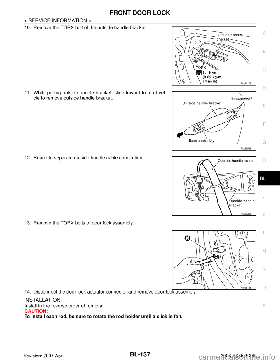
10. Remove the TORX bolt of the outside handle bracket.
11. While pulling outside handle bracket, slide toward front of vehi- cle to remove outside handle bracket.
12. Reach to separate outside handle cable connection.
13. Remove the TORX bolts of door lock assembly.
14. Disconnect the door lock actuator connector and remove door lock assembly.
INSTALLATION
Install in the reverse order of removal.
CAUTION:
To install each rod, be sure to rotate the rod holder until a click is felt.
PIIA7117E
PIIA3558E
PIIA6026E
PIIB5812E
3AA93ABC3ACD3AC03ACA3AC03AC63AC53A913A773A893A873A873A8E3A773A983AC73AC93AC03AC3
3A893A873A873A8F3A773A9D3AAF3A8A3A8C3A863A9D3AAF3A8B3A8C
Page 873 of 3924
REAR DOOR LOCKBL-139
< SERVICE INFORMATION >
C
DE
F
G H
J
K L
M A
B
BL
N
O P
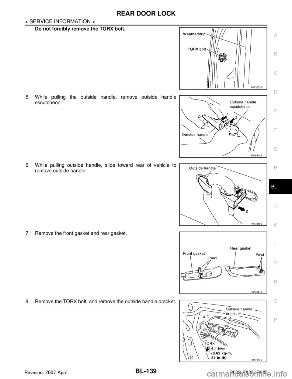
Do not forcibly remove the TORX bolt.
5. While pulling the outside handle, remove outside handle escutcheon.
6. While pulling outside handle, slide toward rear of vehicle to remove outside handle.
7. Remove the front gasket and rear gasket.
8. Remove the TORX bolt, and remove the outside handle bracket.
PIIA3553E
PIIA6344E
PIIA3555E
PIIA3557E
PIIA7117E
3AA93ABC3ACD3AC03ACA3AC03AC63AC53A913A773A893A873A873A8E3A773A983AC73AC93AC03AC3
3A893A873A873A8F3A773A9D3AAF3A8A3A8C3A863A9D3AAF3A8B3A8C
Page 874 of 3924
BL-140
< SERVICE INFORMATION >
REAR DOOR LOCK
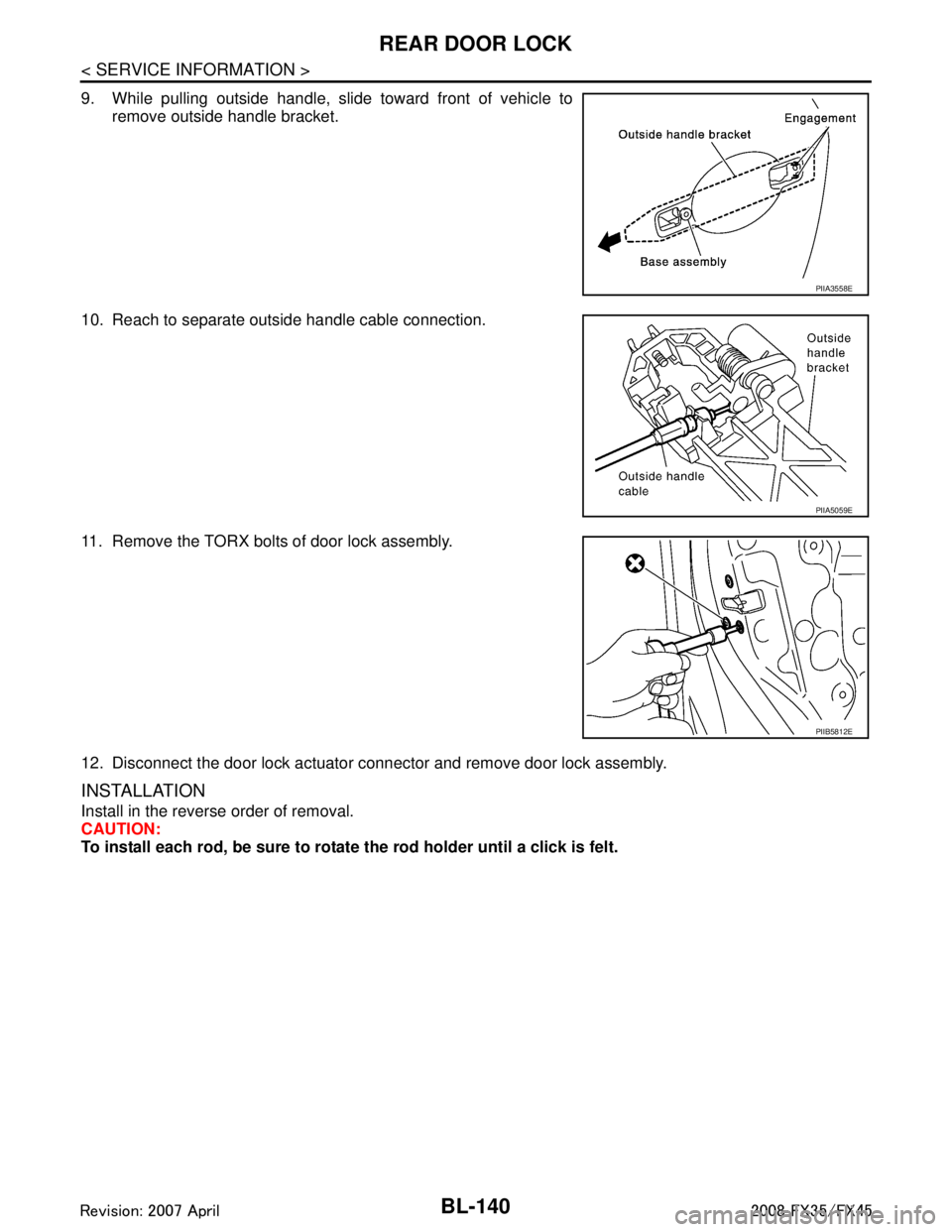
9. While pulling outside handle, slide toward front of vehicle toremove outside handle bracket.
10. Reach to separate outside handle cable connection.
11. Remove the TORX bolts of door lock assembly.
12. Disconnect the door lock actuator connector and remove door lock assembly.
INSTALLATION
Install in the reverse order of removal.
CAUTION:
To install each rod, be sure to rotate the rod holder until a click is felt.
PIIA3558E
PIIA5059E
PIIB5812E
3AA93ABC3ACD3AC03ACA3AC03AC63AC53A913A773A893A873A873A8E3A773A983AC73AC93AC03AC3
3A893A873A873A8F3A773A9D3AAF3A8A3A8C3A863A9D3AAF3A8B3A8C
Page 1021 of 3924
![INFINITI FX35 2008 User Guide
BRC-6
< SERVICE INFORMATION >[VDC/TCS/ABS]
PRECAUTIONS
If the following components are replaced with non-genui
ne components or converted, VDC OFF indicator
lamp and SLIP indicator lamp may turn on INFINITI FX35 2008 User Guide
BRC-6
< SERVICE INFORMATION >[VDC/TCS/ABS]
PRECAUTIONS
If the following components are replaced with non-genui
ne components or converted, VDC OFF indicator
lamp and SLIP indicator lamp may turn on](/img/42/57017/w960_57017-1020.png)
BRC-6
< SERVICE INFORMATION >[VDC/TCS/ABS]
PRECAUTIONS
If the following components are replaced with non-genui
ne components or converted, VDC OFF indicator
lamp and SLIP indicator lamp may turn on or the VDC system may not operate properly. Components
related to suspension (shock absorber, strut, spring, bushing, etc.), Tires, wheels (exclude specified size),
components related to brake (pad, rotor, caliper, etc. ), components related to engine (muffler, ECM, etc.),
components related to body reinforcement (roll bar, tower bar, etc.).
Driving in the condition of breakage or excessive wear of suspension, tires or components related to the
brakes may cause VDC OFF indicator lamp and SLIP indicator lamp turn on, and the VDC system may not
operate properly.
When the TCS or VDC is activated by sudden accele ration or sudden turn, some noise may occur. The
noise is a result of the normal operation of the TCS and VDC.
When driving on roads which have extreme slopes (s uch as mountainous roads) or high banks (such as
sharp carves on a freeway), the VDC may not operate nor mally, or VDC OFF indicator lamp and SLIP indi-
cator lamp may turn on. However, this is not a malfunction, if normal operation can be resumed after restart-
ing engine.
Sudden turns (such as spin turns, acceleration turns) , drifting, etc. When VDC function is OFF (VDC OFF
SW ON) may cause the G sensor system indicate a malf unction. However, this is not a malfunction, if nor-
mal operation can be resumed after restarting engine.
Change 4 tires at a time. Be sure to use specified- size tires that have the same brand name and pattern.
Wheel sensor errors can be detected be self-diagnosis when tires have wide abrasion variations or the size
is different from the genuine tires.
3AA93ABC3ACD3AC03ACA3AC03AC63AC53A913A773A893A873A873A8E3A773A983AC73AC93AC03AC3
3A893A873A873A8F3A773A9D3AAF3A8A3A8C3A863A9D3AAF3A8B3A8C
Page 1147 of 3924

COMBINATION METERSDI-21
< SERVICE INFORMATION >
C
DE
F
G H
I
J
L
M A
B
DI
N
O P
Fuel Gauge Pointer Fluctuates, Indicator Wrong Value or VariesINFOID:0000000001328449
1.CHECK FUEL GAUGE FLUCTUATION
Test drive vehicle to see if gauge fluctuates onl y during driving or at the instant of stopping.
Does the indication value vary only during driving or at the instant of stopping?
YES >> The pointer fluctuation may be caused by fuel level change in the fuel tank. Condition is normal.
NO >> Ask the customer about the situation when the symptom occurs in detail, and perform the trouble
diagnosis.
Fuel Gauge Does Not Move to FULL PositionINFOID:0000000001328450
1.QUESTION 1
Does it take a long time for the pointer to move to FULL position?
YES >> GO TO 2.
NO >> GO TO 3.
2.QUESTION 2
Was the vehicle fueled with the ignition switch ON?
YES >> Be sure to fuel the vehicle with the ignition swit ch OFF. Otherwise, it will take a long time to move
to FULL position because of the c haracteristic of the fuel gauge.
NO >> GO TO 3.
3.QUESTION 3
Is the vehicle parked on an incline?
YES >> Check the fuel level indication with vehicle on a level surface.
NO >> GO TO 4.
4.QUESTION 4
During driving, does the fuel gauge pointer move gradually toward EMPTY position?
YES >> Check the fuel level sensor unit. Refer to DI-21, "Electrical Component Inspection".
NO >> The float arm may interfere or bind with any of the components in the fuel tank.
Odo/Trip Meter and Illuminati on Control Switch InspectionINFOID:0000000001328451
Symptom: Illumination control does not operate.
1.CHECK ODO/TRIP METER AND I LLUMINATION CONTROL SWITCH
1. Remove odo/trip meter and illumination control switch. Refer to DI-24, "
Removal and Installation of Odo/
Trip Meter and Illumination Control Switch".
2. Check continuity odo/trip meter and illumination control switch. Refer to DI-21, "
Electrical Component
Inspection".
OK or NG
OK >> Replace combination meter.
NG >> Replace odo/trip meter and illumination control switch.
Electrical Component InspectionINFOID:0000000001328452
ODO/TRIP METER AND ILLUMINATION CONTROL SWITCH
3AA93ABC3ACD3AC03ACA3AC03AC63AC53A913A773A893A873A873A8E3A773A983AC73AC93AC03AC3
3A893A873A873A8F3A773A9D3AAF3A8A3A8C3A863A9D3AAF3A8B3A8C