warning INFINITI FX35 2008 Service Manual
[x] Cancel search | Manufacturer: INFINITI, Model Year: 2008, Model line: FX35, Model: INFINITI FX35 2008Pages: 3924, PDF Size: 81.37 MB
Page 3193 of 3924
TURN SIGNAL AND HAZARD WARNING LAMPSLT-91
< SERVICE INFORMATION >
C
DE
F
G H
I
J
L
M A
B
LT
N
O P
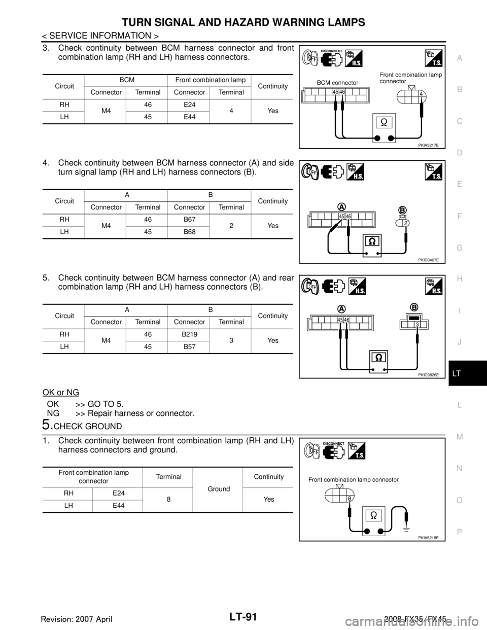
3. Check continuity between BCM harness connector and front combination lamp (RH and LH) harness connectors.
4. Check continuity between BCM harness connector (A) and side turn signal lamp (RH and LH) harness connectors (B).
5. Check continuity between BCM harness connector (A) and rear combination lamp (RH and LH) harness connectors (B).
OK or NG
OK >> GO TO 5.
NG >> Repair harness or connector.
5.CHECK GROUND
1. Check continuity between front combination lamp (RH and LH) harness connectors and ground.
Circuit BCM Front combination lamp
Continuity
Connector Terminal Connector Terminal
RH M4 46 E24
4Yes
LH 45 E44
PKIA5217E
Circuit AB
Continuity
Connector Terminal Connector Terminal
RH M4 46 B67
2Yes
LH 45 B68
PKID0467E
Circuit AB
Continuity
Connector Terminal Connector Terminal
RH M4 46 B219
3Yes
LH 45 B57
PKIC9826E
Front combination lamp
connector Terminal
GroundContinuity
RH E24 8Yes
LH E44
PKIA5218E
3AA93ABC3ACD3AC03ACA3AC03AC63AC53A913A773A893A873A873A8E3A773A983AC73AC93AC03AC3
3A893A873A873A8F3A773A9D3AAF3A8A3A8C3A863A9D3AAF3A8B3A8C
Page 3194 of 3924
LT-92
< SERVICE INFORMATION >
TURN SIGNAL AND HAZARD WARNING LAMPS
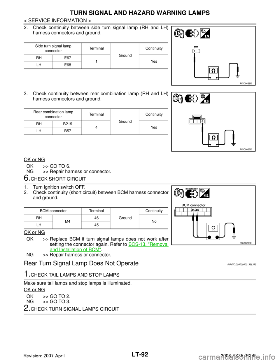
2. Check continuity between side turn signal lamp (RH and LH)harness connectors and ground.
3. Check continuity between rear combination lamp (RH and LH) harness connectors and ground.
OK or NG
OK >> GO TO 6.
NG >> Repair harness or connector.
6.CHECK SHORT CIRCUIT
1. Turn ignition switch OFF.
2. Check continuity (short circuit) between BCM harness connector and ground.
OK or NG
OK >> Replace BCM if turn signal lamps does not work after setting the connector again. Refer to BCS-13, "
Removal
and Installation of BCM".
NG >> Repair harness or connector.
Rear Turn Signal Lam p Does Not OperateINFOID:0000000001328355
1.CHECK TAIL LAMPS AND STOP LAMPS
Make sure tail lamps and stop lamps is illuminated.
OK or NG
OK >> GO TO 2.
NG >> GO TO 3.
2.CHECK TURN SIGNAL LAMPS CIRCUIT
Side turn signal lamp connector Te r m i n a l
GroundContinuity
RH E67 1Yes
LH E68
PKID0468E
Rear combination lamp
connector Te r m i n a l
GroundContinuity
RH B219 4Yes
LH B57
PKIC9827E
BCM connector Terminal
GroundContinuity
RH M4 46
No
LH 45
PKIA6289E
3AA93ABC3ACD3AC03ACA3AC03AC63AC53A913A773A893A873A873A8E3A773A983AC73AC93AC03AC3
3A893A873A873A8F3A773A9D3AAF3A8A3A8C3A863A9D3AAF3A8B3A8C
Page 3195 of 3924
TURN SIGNAL AND HAZARD WARNING LAMPSLT-93
< SERVICE INFORMATION >
C
DE
F
G H
I
J
L
M A
B
LT
N
O P
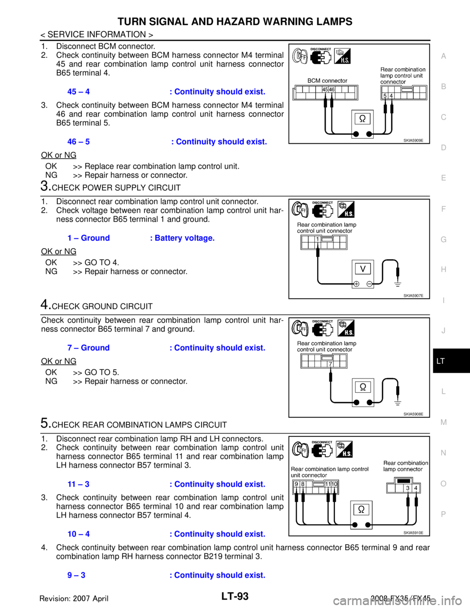
1. Disconnect BCM connector.
2. Check continuity between BCM harness connector M4 terminal 45 and rear combination lamp control unit harness connector
B65 terminal 4.
3. Check continuity between BCM harness connector M4 terminal 46 and rear combination lamp control unit harness connector
B65 terminal 5.
OK or NG
OK >> Replace rear combination lamp control unit.
NG >> Repair harness or connector.
3.CHECK POWER SUPPLY CIRCUIT
1. Disconnect rear combination lamp control unit connector.
2. Check voltage between rear combination lamp control unit har- ness connector B65 terminal 1 and ground.
OK or NG
OK >> GO TO 4.
NG >> Repair harness or connector.
4.CHECK GROUND CIRCUIT
Check continuity between rear combination lamp control unit har-
ness connector B65 terminal 7 and ground.
OK or NG
OK >> GO TO 5.
NG >> Repair harness or connector.
5.CHECK REAR COMBINATION LAMPS CIRCUIT
1. Disconnect rear combination lamp RH and LH connectors.
2. Check continuity between rear combination lamp control unit harness connector B65 terminal 11 and rear combination lamp
LH harness connector B57 terminal 3.
3. Check continuity between rear combination lamp control unit harness connector B65 terminal 10 and rear combination lamp
LH harness connector B57 terminal 4.
4. Check continuity between rear combination lamp control unit harness connector B65 terminal 9 and rear
combination lamp RH harness connector B219 terminal 3. 45 – 4 : Continui
ty should exist.
46 – 5 : Continuity should exist.
SKIA5909E
1 – Ground : Battery voltage.
SKIA5907E
7 – Ground : Continuity should exist.
SKIA5908E
11 – 3 : Continuity should exist.
10 – 4 : Continui ty should exist.
9 – 3 : Continui ty should exist.
SKIA5910E
3AA93ABC3ACD3AC03ACA3AC03AC63AC53A913A773A893A873A873A8E3A773A983AC73AC93AC03AC3
3A893A873A873A8F3A773A9D3AAF3A8A3A8C3A863A9D3AAF3A8B3A8C
Page 3196 of 3924
LT-94
< SERVICE INFORMATION >
TURN SIGNAL AND HAZARD WARNING LAMPS
5. Check continuity between rear combination lamp control unit harness connector B65 terminal 8 and rearcombination lamp RH harness connector B219 terminal 4.
OK or NG
OK >> Replace rear combination lamp control unit or rear combination lamp, and then check if turn signal
lamps is illuminated.
NG >> Repair harness or connector.
Hazard Warning Lamp Does Not Oper ate But Turn Signal Lamp OperatesINFOID:0000000001381754
1.CHECK HAZARD SWITCH INPUT SIGNAL
With CONSULT-III
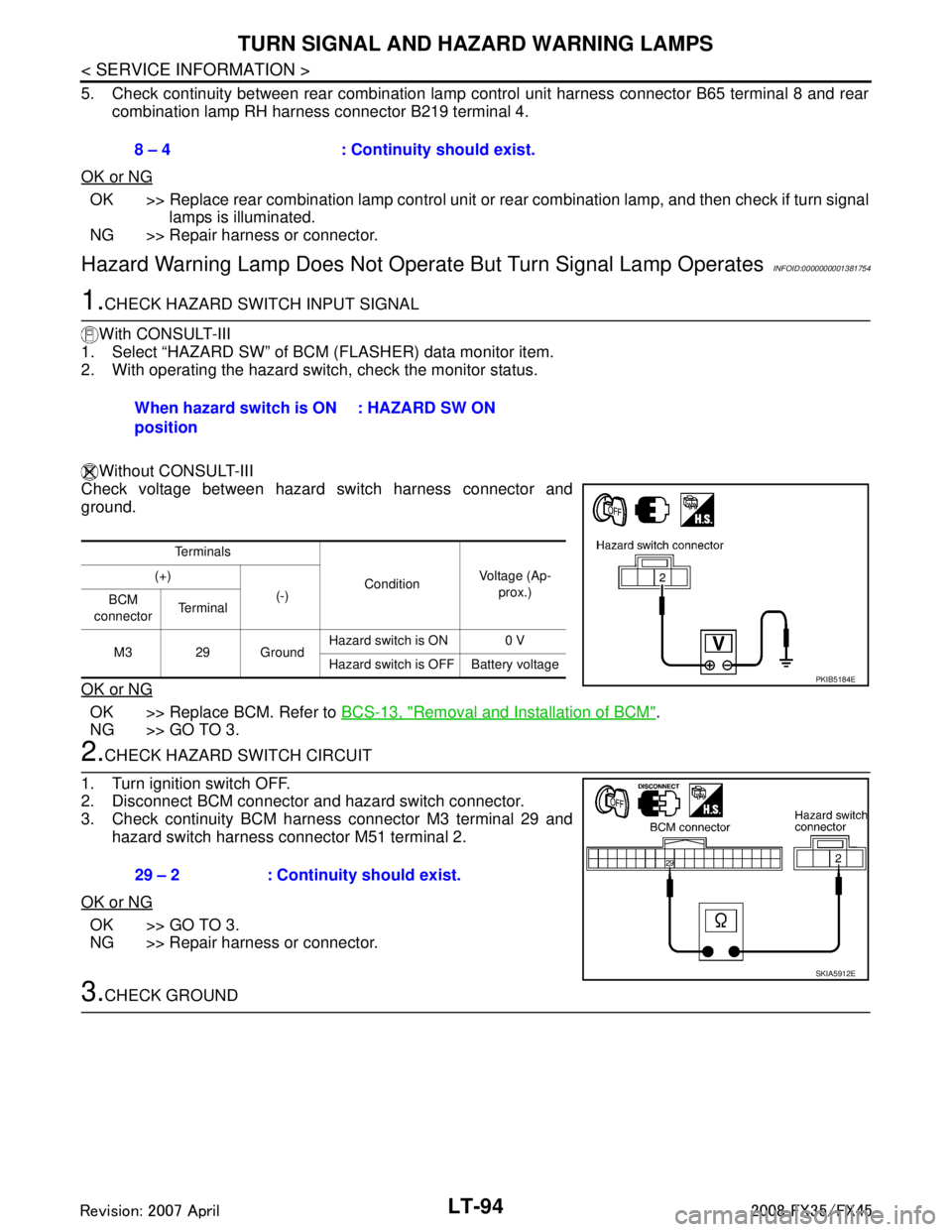
1. Select “HAZARD SW” of BCM (FLASHER) data monitor item.
2. With operating the hazard switch, check the monitor status.
Without CONSULT-III
Check voltage between hazard switch harness connector and
ground.
OK or NG
OK >> Replace BCM. Refer to BCS-13, "Removal and Installation of BCM".
NG >> GO TO 3.
2.CHECK HAZARD SWITCH CIRCUIT
1. Turn ignition switch OFF.
2. Disconnect BCM connector and hazard switch connector.
3. Check continuity BCM harness connector M3 terminal 29 and
hazard switch harness connector M51 terminal 2.
OK or NG
OK >> GO TO 3.
NG >> Repair harness or connector.
3.CHECK GROUND 8 – 4 : Continuity should exist.
When hazard switch is ON
position
: HAZARD SW ON
Te r m i n a l s
ConditionVoltage (Ap-
prox.)
(+)
(-)
BCM
connector Te r m i n a l
M3 29 Ground Hazard switch is ON 0 V
Hazard switch is OFF Battery voltage
PKIB5184E
29 – 2 : Continuity should exist.
SKIA5912E
3AA93ABC3ACD3AC03ACA3AC03AC63AC53A913A773A893A873A873A8E3A773A983AC73AC93AC03AC3
3A893A873A873A8F3A773A9D3AAF3A8A3A8C3A863A9D3AAF3A8B3A8C
Page 3197 of 3924
TURN SIGNAL AND HAZARD WARNING LAMPSLT-95
< SERVICE INFORMATION >
C
DE
F
G H
I
J
L
M A
B
LT
N
O P
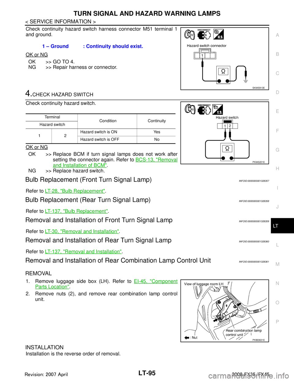
Check continuity hazard switch harness connector M51 terminal 1
and ground.
OK or NG
OK >> GO TO 4.
NG >> Repair harness or connector.
4.CHECK HAZARD SWITCH
Check continuity hazard switch.
OK or NG
OK >> Replace BCM if turn signal lamps does not work after setting the connector again. Refer to BCS-13, "
Removal
and Installation of BCM".
NG >> Replace hazard switch.
Bulb Replacement (Fr ont Turn Signal Lamp)INFOID:0000000001328357
Refer to LT-28, "Bulb Replacement".
Bulb Replacement (Rear Turn Signal Lamp)INFOID:0000000001328358
Refer to LT-137, "Bulb Replacement".
Removal and Installation of Front Turn Signal LampINFOID:0000000001328359
Refer to LT-30, "Removal and Installation".
Removal and Installation of Rear Turn Signal LampINFOID:0000000001328360
Refer to LT-137, "Removal and Installation".
Removal and Installation of Rear Combination Lamp Control UnitINFOID:0000000001328361
REMOVAL
1. Remove luggage side box (LH). Refer to EI-45, "Component
Parts Location".
2. Remove nuts (2), and remove rear combination lamp control unit.
INSTALLATION
Installation is the reverse order of removal. 1 – Ground : Continuity should exist.
SKIA5913E
Te r m i n a l
Condition Continuity
Hazard switch
12 Hazard switch is ON Yes
Hazard switch is OFF No
PKIA5221E
PKIB3631E
3AA93ABC3ACD3AC03ACA3AC03AC63AC53A913A773A893A873A873A8E3A773A983AC73AC93AC03AC3
3A893A873A873A8F3A773A9D3AAF3A8A3A8C3A863A9D3AAF3A8B3A8C
Page 3291 of 3924
![INFINITI FX35 2008 Service Manual
LU-6
< SERVICE INFORMATION >[VQ35DE]
ENGINE OIL
WARNING:
• Be careful not to get burn your
self, as engine oil may be hot.
Oil pressure check should be done in “Parking position”.
1. Check t INFINITI FX35 2008 Service Manual
LU-6
< SERVICE INFORMATION >[VQ35DE]
ENGINE OIL
WARNING:
• Be careful not to get burn your
self, as engine oil may be hot.
Oil pressure check should be done in “Parking position”.
1. Check t](/img/42/57017/w960_57017-3290.png)
LU-6
< SERVICE INFORMATION >[VQ35DE]
ENGINE OIL
WARNING:
• Be careful not to get burn your
self, as engine oil may be hot.
Oil pressure check should be done in “Parking position”.
1. Check the engine oil level. Refer to "ENGINE OIL LEVEL".
2. Remove front engine undercover with power tool.
3. Disconnect harness connector at oil pressure sensor, and remove oil pressure sensor using deep socket (commercial ser-
vice tool).
CAUTION:
Do not drop or shock oil pressure switch.
4. Install the oil pressure gauge (SST) and hose (SST).
5. Start the engine and warm it up to normal operating temperature.
6. Check the engine oil pressure with engine running under no-load. NOTE:
When the engine oil temperature is low, the engine oil pressure becomes high.
Engine oil pressure [Engi ne oil temperature at 80 °C (176 °F)]
Unit: kPa (kg/cm2, psi)
If difference is extreme, check engine oil passage and oil pump for engine oil leaks.
7. After the inspections, install oil pressure switch as follows:
a. Remove old liquid gasket adhering to oil pressure switch and the mating surface.
b. Apply liquid gasket and tighten oil pressure switch to the specification. Use Genuine RTV Silicone Seal ant or equivalent. Refer to GI-44, "
Recommended Chemical Prod-
uct and Sealant".
SBIA0452E
SBIA0453E
SLC926
Engine speed Approximate discharge pressure
Idle speed More than 98 (1.0, 14)2,000 rpm More than 294 (3.0, 43)
3AA93ABC3ACD3AC03ACA3AC03AC63AC53A913A773A893A873A873A8E3A773A983AC73AC93AC03AC3
3A893A873A873A8F3A773A9D3AAF3A8A3A8C3A863A9D3AAF3A8B3A8C
Page 3292 of 3924
![INFINITI FX35 2008 Service Manual
ENGINE OILLU-7
< SERVICE INFORMATION > [VQ35DE]
C
D
E
F
G H
I
J
K L
M A
LU
NP
Oc. After warming up engine, make sure there is no leakage of engine oil with running engine.
Changing Engine OilINFOID:0 INFINITI FX35 2008 Service Manual
ENGINE OILLU-7
< SERVICE INFORMATION > [VQ35DE]
C
D
E
F
G H
I
J
K L
M A
LU
NP
Oc. After warming up engine, make sure there is no leakage of engine oil with running engine.
Changing Engine OilINFOID:0](/img/42/57017/w960_57017-3291.png)
ENGINE OILLU-7
< SERVICE INFORMATION > [VQ35DE]
C
D
E
F
G H
I
J
K L
M A
LU
NP
Oc. After warming up engine, make sure there is no leakage of engine oil with running engine.
Changing Engine OilINFOID:0000000001325814
WARNING:
Be careful not to get burn yourself, as engine oil may be hot.
Prolonged and repeated contact with used engine
oil may cause skin cancer. Try to avoid direct skin
contact with used engine oil. If skin contact is made, wash thorough ly with soap or hand cleaner as
soon as possible.
1. Remove front engine undercover with power tool.
2. Warm up the engine, and check for engine oil leakage from engine components. Refer to LU-5, "
Inspec-
tion".
3. Stop the engine and wait for 10 minutes.
4. Loosen oil filler cap and then remove drain plug.
5. Drain engine oil.
6. Install drain plug with new washer. Refer to EM-30, "
Component (2WD Models)".
CAUTION:
Be sure to clean drain plug and install with new washer.
7. Refill with new engine oil. Engine oil specificat ion and viscosity:
Refer to MA-9, "
Fluids and Lubricants".
Engine oil capacity (Approximate):
Unit: (US qt, lmp qt)
CAUTION:
When filling engine oil, do not pull out oil level gauge.
The refill capacity depends on the engine oi l temperature and drain time. Use these specifica-
tions for reference only.
Always use oil level gauge to determine the proper amount of engine oil in engine.
8. Warm up the engine and check area around drain plug and oil filter for engine oil leakage.
9. Stop the engine and wait for 10 minutes.
10. Check the engine oil level. Refer to LU-5, "
Inspection".
Oil pressure switch:
: 14.8 N·m (1.5 kg-m, 11 ft-lb)
Oil pan drain plug: : 34.3 N·m (3.5 kg-m, 25 ft-lb)
Drain and refill With oil filter change 4.7 (5, 4-1/8)
Without oil filter change 4.4 (4-5/8, 3-7/8)
Dry engine (Overhaul) 5.4 (5-3/4, 4-3/4)
3AA93ABC3ACD3AC03ACA3AC03AC63AC53A913A773A893A873A873A8E3A773A983AC73AC93AC03AC3
3A893A873A873A8F3A773A9D3AAF3A8A3A8C3A863A9D3AAF3A8B3A8C
Page 3295 of 3924
![INFINITI FX35 2008 Service Manual
LU-10
< SERVICE INFORMATION >[VQ35DE]
OIL FILTER BRACKET (AWD)
OIL FILTER BRACKET (AWD)
ComponentINFOID:0000000001325816
Removal and InstallationINFOID:0000000001325817
REMOVAL
WARNING:
Be careful no INFINITI FX35 2008 Service Manual
LU-10
< SERVICE INFORMATION >[VQ35DE]
OIL FILTER BRACKET (AWD)
OIL FILTER BRACKET (AWD)
ComponentINFOID:0000000001325816
Removal and InstallationINFOID:0000000001325817
REMOVAL
WARNING:
Be careful no](/img/42/57017/w960_57017-3294.png)
LU-10
< SERVICE INFORMATION >[VQ35DE]
OIL FILTER BRACKET (AWD)
OIL FILTER BRACKET (AWD)
ComponentINFOID:0000000001325816
Removal and InstallationINFOID:0000000001325817
REMOVAL
WARNING:
Be careful not to get burn yourself, as engine oil may be hot.
1. Remove front engine undercover with power tool.
2. Using the oil filter wrench [SST: KV10115801 (J38956)], remove oil filter. Refer to
LU-8, "
Removal and
Installation".
CAUTION:
Do not spill engine oil on drive belt.
3. Remove oil cooler connector bolt, and then oil cooler with water hoses connected.
4. Disconnect oil temperature sensor and oi l pressure switch harness connectors.
5. Remove oil filter bracket from oil pan (upper).
6. Remove oil temperature sensor and oil pr essure switch from oil filter bracket.
INSTALLATION
Note the following, and install in the reverse order of removal.
Install oil pressure switch and oil temperature sensor as follows:
- Remove old liquid gasket adhering to oil pressure switch and oil filter bracket.
- Apply liquid gasket and install oil pressure switch, and then oil temperature sensor with a new washer.
Use Genuine RTV Silicone Seal ant or equivalent. Refer to GI-44, "
Recommended Chemical Product
and Sealant".
1. Oil filter 2. Connector bolt 3. Oil cooler
4. O-ring 5. Relief valve 6. Oil filter bracket
7. Gasket 8. Oil pressure switch 9. Oil temperature sensor
10. Washer 11. Oil pan (upper)
SBIA0593E
3AA93ABC3ACD3AC03ACA3AC03AC63AC53A913A773A893A873A873A8E3A773A983AC73AC93AC03AC3
3A893A873A873A8F3A773A9D3AAF3A8A3A8C3A863A9D3AAF3A8B3A8C
Page 3298 of 3924
![INFINITI FX35 2008 Service Manual
OIL COOLERLU-13
< SERVICE INFORMATION > [VQ35DE]
C
D
E
F
G H
I
J
K L
M A
LU
NP
O
AWD models
Removal and InstallationINFOID:0000000001325819
REMOVAL
WARNING:
Be careful not to get burn yourself, as en INFINITI FX35 2008 Service Manual
OIL COOLERLU-13
< SERVICE INFORMATION > [VQ35DE]
C
D
E
F
G H
I
J
K L
M A
LU
NP
O
AWD models
Removal and InstallationINFOID:0000000001325819
REMOVAL
WARNING:
Be careful not to get burn yourself, as en](/img/42/57017/w960_57017-3297.png)
OIL COOLERLU-13
< SERVICE INFORMATION > [VQ35DE]
C
D
E
F
G H
I
J
K L
M A
LU
NP
O
AWD models
Removal and InstallationINFOID:0000000001325819
REMOVAL
WARNING:
Be careful not to get burn yourself, as en
gine oil and engine coolant may be hot.
NOTE:
When removing oil cooler only, step 2 is unnecessary.
1. Remove front engine undercover with power tool.
2. Drain engine coolant from radiator and cylinder block. Refer to CO-10, "
Changing Engine Coolant" and
EM-123, "
Disassembly and Assembly".
NOTE:
Perform this step when removing water pipes.
3. Disconnect water hoses from oil cooler. When removing oil cooler only, pinching water hoses near oil cooler to prevent engine coolant from spill-
ing out.
Remaining engine coolant in piping will come out. Use a tray to collect it.
CAUTION:
Perform this step when the engine is cold.
Do not spill engine coolant on drive belts.
4. Using oil filter wrench [SST: KV10115801 (J38956)], remove oil filter. Refer to LU-8, "
Removal and Instal-
lation".
CAUTION:
Do not spill engine oil on drive belts.
5. Remove connector bolt, and remove oil cooler. CAUTION:
Do not spill engine oil to rubber parts such as drive belts and engine mounting insulator.
SBIA0584E
1. Oil filter 2. Connector bolt 3. Oil cooler
4. O-ring 5. Relief valve 6. Oil filter bracket
7. Water hose 8. Water hose 9. Water pipe
10. Water hose
3AA93ABC3ACD3AC03ACA3AC03AC63AC53A913A773A893A873A873A8E3A773A983AC73AC93AC03AC3
3A893A873A873A8F3A773A9D3AAF3A8A3A8C3A863A9D3AAF3A8B3A8C
Page 3308 of 3924
![INFINITI FX35 2008 Service Manual
ENGINE OILLU-23
< SERVICE INFORMATION > [VK45DE]
C
D
E
F
G H
I
J
K L
M A
LU
NP
O
ENGINE OIL
InspectionINFOID:0000000001325829
ENGINE OIL LEVEL
NOTE:
Before starting engine, put vehicle horizontally a INFINITI FX35 2008 Service Manual
ENGINE OILLU-23
< SERVICE INFORMATION > [VK45DE]
C
D
E
F
G H
I
J
K L
M A
LU
NP
O
ENGINE OIL
InspectionINFOID:0000000001325829
ENGINE OIL LEVEL
NOTE:
Before starting engine, put vehicle horizontally a](/img/42/57017/w960_57017-3307.png)
ENGINE OILLU-23
< SERVICE INFORMATION > [VK45DE]
C
D
E
F
G H
I
J
K L
M A
LU
NP
O
ENGINE OIL
InspectionINFOID:0000000001325829
ENGINE OIL LEVEL
NOTE:
Before starting engine, put vehicle horizontally and check
the engine oil level. If engine is already started, stop
it and allow 15 minutes before checking.
1. Pull out oil level gauge and wipe it clean.
2. Insert oil level gauge and make sure the engine oil level is within the range shown in the figure.
3. If it is out of range, adjust it.
ENGINE OIL APPEARANCE
Check engine oil for white turbidity or heavy contamination.
If engine oil becomes turbid and white, it is highl y probable that it is contaminated with engine coolant.
Repair or replace damaged parts.
ENGINE OIL LEAKAGE
Check for oil leakage around the following area.
Oil pan
Oil pan drain plug
Oil pressure switch
Oil filter
Oil cooler
Intake valve timing control cover
Intake valve timing control solenoid valve
Front cover
Chain tensioner cover
Mating surface between cylinder block and cylinder head
Mating surface between cylinder head and rocker cover
Crankshaft oil seals (front and rear)
OIL PRESSURE CHECK
WARNING:
Be careful not to burn yoursel f, as engine oil may be hot.
Oil pressure check should be done in “Parking position”.
1. Check the engine oil level. Refer to "ENGINE OIL LEVEL".
2. Remove front engine undercover with power tool.
3. Disconnect harness connector at oil pressure switch, and remove oil pressure switch using deep socket (commercial ser-
vice tool).
CAUTION:
Do not drop or shock oil pressure switch.
PBIC0801E
PBIC1524E
3AA93ABC3ACD3AC03ACA3AC03AC63AC53A913A773A893A873A873A8E3A773A983AC73AC93AC03AC3
3A893A873A873A8F3A773A9D3AAF3A8A3A8C3A863A9D3AAF3A8B3A8C