engine stall INFINITI FX35 2008 Service Manual
[x] Cancel search | Manufacturer: INFINITI, Model Year: 2008, Model line: FX35, Model: INFINITI FX35 2008Pages: 3924, PDF Size: 81.37 MB
Page 2805 of 3924

FFD-14
< SERVICE INFORMATION >
FRONT FINAL DRIVE ASSEMBLY
FRONT FINAL DRIVE ASSEMBLY
Removal and Installation (VQ35DE Models)INFOID:0000000001327485
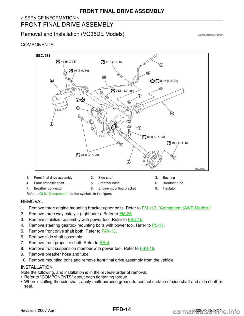
COMPONENTS
REMOVAL
1. Remove three engine mounting bracket upper bolts. Refer to EM-117, "Component (AWD Models)".
2. Remove three way catalyst (right bank). Refer to EM-26
.
3. Remove stabilizer assembly with power tool. Refer to FSU-15
.
4. Remove steering gearbox mounting bolts with power tool. Refer to PS-17
.
5. Remove front drive shaft both. Refer to FA X - 1 3
.
6. Remove side shaft assembly.
7. Remove front propeller shaft. Refer to PR-4
.
8. Remove front suspension member with power tool. Refer to FSU-16
.
9. Remove breather hose and tube.
10. Remove mounting bolts and remove front final drive assembly from the vehicle.
INSTALLATION
Note the following, and installation is in the reverse order of removal.
Refer to "COMPONENTS" about each tightening torque.
When installing the side shaft, apply multi-purpose grease to contact surface of side shaft and side shaft oil
seal.
1. Front final drive assembly 2. Side shaft 3. Bushing
4. Front propeller shaft 5. Breather hose 6. Breather tube
7. Breather connector 8. Engine mounting bracket 9. Insulator
Refer to GI-8, "
Component", for the symbols in the figure.
PDIA0789J
3AA93ABC3ACD3AC03ACA3AC03AC63AC53A913A773A893A873A873A8E3A773A983AC73AC93AC03AC3
3A893A873A873A8F3A773A9D3AAF3A8A3A8C3A863A9D3AAF3A8B3A8C
Page 2807 of 3924

FFD-16
< SERVICE INFORMATION >
FRONT FINAL DRIVE ASSEMBLY
REMOVAL
1. Remove three way catalyst (right bank). Refer to EM-179.
2. Remove stabilizer assembly with power tool. Refer to FSU-15
.
3. Remove steering gearbox mounting bolts with power tool. Refer to PS-17
.
4. Remove front drive shaft both. Refer to FA X - 1 3
.
5. Remove side shaft assembly.
6. Remove front propeller shaft. Refer to PR-4
.
7. Remove front suspension member with power tool. Refer to FSU-16
.
8. Remove engine wire harness clamp bolts from front final drive.
9. Remove breather hose and tube.
10. Remove mounting bolts and remove front final drive assembly from the vehicle.
INSTALLATION
Note the following, and installation is in the reverse order of removal.
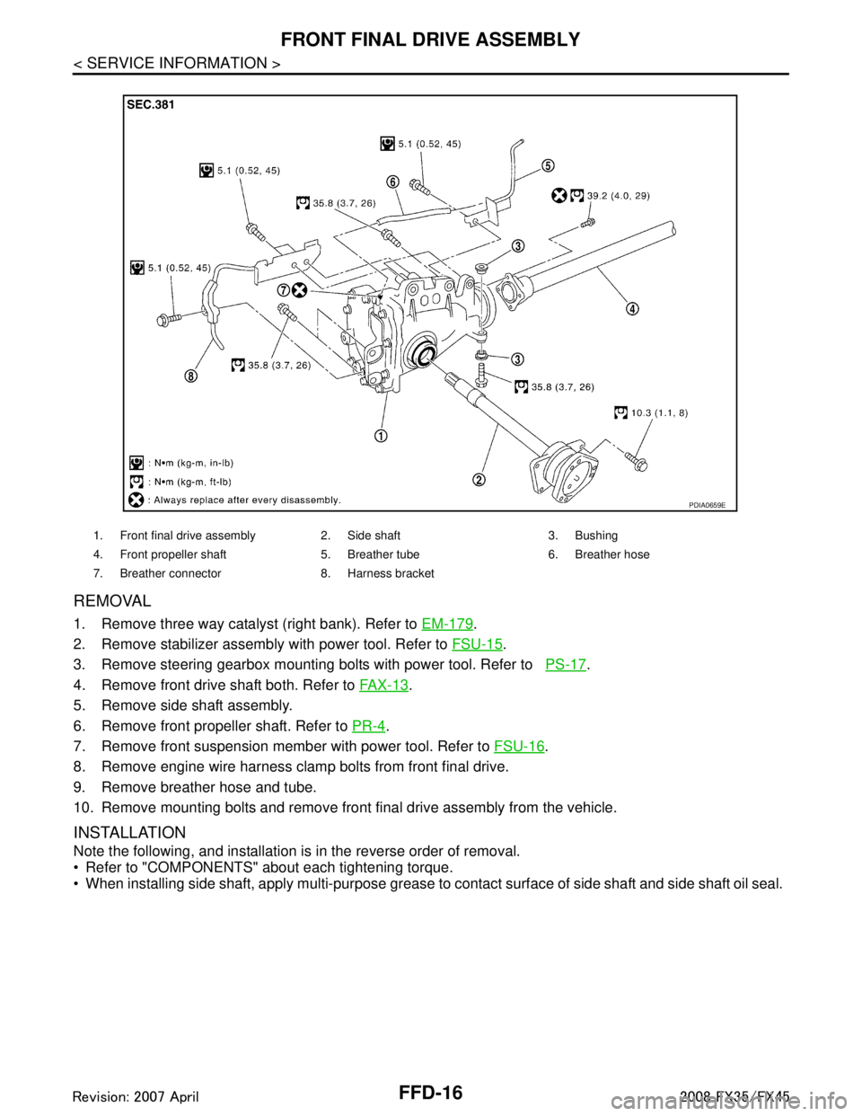
Refer to "COMPONENTS" about each tightening torque.
When installing side shaft, apply multi-purpose grease to contact surface of side shaft and side shaft oil seal.
1. Front final drive assembly 2. Side shaft 3. Bushing
4. Front propeller shaft 5. Breather tube 6. Breather hose
7. Breather connector 8. Harness bracket
PDIA0659E
3AA93ABC3ACD3AC03ACA3AC03AC63AC53A913A773A893A873A873A8E3A773A983AC73AC93AC03AC3
3A893A873A873A8F3A773A9D3AAF3A8A3A8C3A863A9D3AAF3A8B3A8C
Page 2833 of 3924

FL-1
ENGINE
C
DE
F
G H
I
J
K L
M
SECTION FL
A
FL
N
O P
CONTENTS
FUEL SYSTEM
SERVICE INFORMATION .. ..........................2
PREPARATION .............................................. .....2
Commercial Service Tool .................................... ......2
FUEL SYSTEM ....................................................3
Checking Fuel Line ............................................. ......3
General Precaution ...................................................3
FUEL LEVEL SENSOR UNIT, FUEL FILTER
AND FUEL PUMP ASSEMBLY ..........................
4
Component .......................................................... ......4
Removal and Installation ..................................... .....4
Component ...............................................................8
Disassembly and Assembly ......................................8
FUEL TANK ..................................... .................10
Component .......................................................... ....10
Removal and Installation .........................................10
SERVICE DATA AND SPECIFICATIONS
(SDS) .................................................................
12
Standard and Limit ..................................................12
3AA93ABC3ACD3AC03ACA3AC03AC63AC53A913A773A893A873A873A8E3A773A983AC73AC93AC03AC3
3A893A873A873A8F3A773A9D3AAF3A8A3A8C3A863A9D3AAF3A8B3A8C
Page 2835 of 3924

FUEL SYSTEMFL-3
< SERVICE INFORMATION >
C
DE
F
G H
I
J
K L
M A
FL
NP
O
FUEL SYSTEM
Checking Fuel LineINFOID:0000000001327104
Inspect fuel lines, fuel filler cap and fuel tank for improper attach-
ment, leaks, cracks, damage, loos
e connections, chafing or deterio-
ration.
If necessary, repair or replace damaged parts.
General PrecautionINFOID:0000000001327105
WARNING:
When replacing fuel line parts, be sure to observe the following.
• Put a “CAUTION: FLAMMABLE” sign in the workshop.
Be sure to work in a well ventila ted area and furnish workshop with a CO
2 fire extinguisher.
Do not smoke while servicing fuel system. Keep open flames and sparks away from the work area.
CAUTION:
Use gasoline required by the regulations for octane number. Refer to GI-5, "
Precaution for Fuel
(Unleaded Premium Gasoline Recommended)".
Before removing fuel line parts, carry out the following procedures:
- Put drained fuel in an explosion-proof containe r and put the lid on securely. Keep the container in
safe area.
- Release fuel pressure from th e fuel lines. Refer to EC-87, "
Fuel Pressure Check" (VQ35DE) or EC-
665, "Fuel Pressure Check" (VK45DE).
- Disconnect negative battery terminal.
Always replace O-ring and clamps with new ones.
Do not kink or twist tubes when they are being installed.
Do not tighten hose clamps excessi vely to avoid damaging hoses.
After connecting fuel tube qu ick connectors, make sure quick
connectors are secure.
Ensure that connector and resin tube do not contact any adja-
cent parts.
After installing tubes, make su re there is no fuel leakage at
connections in the following steps.
- Apply fuel pressure to fuel li nes with turning ignition switch
“ON” (with engine stopped). Th en check for fuel leaks at con-
nections.
- Start engine and rev it up and check for fuel leaks at connec- tions.
Use only a genuine NISSAN fuel filler cap as a replacement. If
an incorrect fuel filler cap is used, the “MIL” may come on.
For servicing “Evaporative Emi ssion System” parts, refer to
EC-40, "
Description" (VQ35DE) or EC-618, "Description"
(VK45DE).
For servicing“On Board Refueling Vapor Recovery (ORVR)”
parts, refer to EC-46, "
System Description" (VQ35DE) or EC-
624, "System Description" (VK45DE).
SMA803A
SBIA0504E
3AA93ABC3ACD3AC03ACA3AC03AC63AC53A913A773A893A873A873A8E3A773A983AC73AC93AC03AC3
3A893A873A873A8F3A773A9D3AAF3A8A3A8C3A863A9D3AAF3A8B3A8C
Page 2843 of 3924

FUEL TANKFL-11
< SERVICE INFORMATION >
C
DE
F
G H
I
J
K L
M A
FL
NP
O
10. Disconnect fuel filler hose, v
ent hose and EVAP hoses at fuel
tank side.
11. Support the lower part of fuel tank with transmission jack. CAUTION:
Support the position that fuel tank mounting bands do not
engage.
12. Remove fuel tank mounting bands.
13. Supporting with hands, descend transmission jack carefully, and remove fuel tank. CAUTION:
Make sure that all connection points have been disconnected.
Confirm there is no interference with vehicle.
14. Remove fuel filler tube protector and fuel filler tube, if necessary.
INSTALLATION
Note the following, and install in the reverse order of removal.
Surely clamp fuel hoses and insert hose to the length below.
Be sure hose clamp is not placed on swelled area of fuel tube.
Tighten fuel hose clamp so that the distance between its lugs becomes to the following.
To connect quick connector, refer to FL-4, "
Removal and Installation".
INSPECTION AFTER INSTALLATION
Use the following procedure to check for fuel leaks.
1. Turn ignition switch “ON” (with engine stopped), and check connections for leakage by applying fuel pres-
sure to fuel piping.
2. Start engine and rev it up and make sure there are no fuel leaks at the fuel system tube and hose connec-
tions.
PBIC1581E
PBIC0878E
Fuel filler hose : 35 mm (1.38 in)
The other hoses : 25 mm (0.98 in)
Fuel tank side : 8 - 12 mm (0.31 - 0.47 in)
Fuel filler tube side : 5.7 - 9.7 mm (0.224 - 0.382 in)
3AA93ABC3ACD3AC03ACA3AC03AC63AC53A913A773A893A873A873A8E3A773A983AC73AC93AC03AC3
3A893A873A873A8F3A773A9D3AAF3A8A3A8C3A863A9D3AAF3A8B3A8C
Page 2846 of 3924

FSU-2
< SERVICE INFORMATION >
PRECAUTIONS
SERVICE INFORMATION
PRECAUTIONS
CautionINFOID:0000000001327533
• When installing rubber bushings, final tightening must be carried out under unladen conditions with tires on
ground. Oil will shorten the life of rubber bushings. Be sure to wipe off any spilled oil.
Unladen conditions mean that fuel, engine coolant and l ubricant are full. Spare tire, jack, hand tools and
mats are in designated positions.
After servicing suspension parts, be sure to check wheel alignment.
Caulking nuts are not reusable. Always use new ones w hen installing. Since new caulking nuts are pre-oiled,
tighten as they are.
Avoid burden to front cross bar.
3AA93ABC3ACD3AC03ACA3AC03AC63AC53A913A773A893A873A873A8E3A773A983AC73AC93AC03AC3
3A893A873A873A8F3A773A9D3AAF3A8A3A8C3A863A9D3AAF3A8B3A8C
Page 2852 of 3924

FSU-8
< SERVICE INFORMATION >
FRONT SUSPENSION ASSEMBLY
REMOVAL
1. Set an engine slinger to engine, then suspend engine.
2. Remove tire from vehicle with power tool.
3. Remove brake caliper with power tool. Hang it in a place where it will not interfere with work. Refer to BR-
18.
4. Remove brake hose lock plate. Then remove brake hose from strut assembly.
5. Remove disc rotor.
6. Remove wheel sensor harness from strut assembly. CAUTION:
Do not pull on wheel sensor harness.
7. Remove undercover with power tool.
8. Remove front cross bar.
9. Remove steering hydraulic piping bracket from front suspension member. Refer to PS-37
.
10. Remove cotter pin at steering outer socket, then loosen mount- ing nut.
11. Use a ball joint remover (SST) to remove steering outer socket from steering knuckle. Be careful not to damage ball joint boot.
CAUTION:
Tighten temporarily mounting nut to prevent damage to
threads and to prevent ball jo int remover (SST) from com-
ing off.
12. Remove mounting bolts of steering gear with power tool, then hang steering gear on vehicle. Refer to PS-17
.
13. Remove front final drive side of drive shaft with power tool. (For AWD models) Refer to FAX-15, "
Removal and Installation (Left
Side)", FAX-16, "Removal and Installation (Right Side)".
14. Set jack under front suspension member.
15. Remove fixing bolts and nuts between strut assembly and steering knuckle with power tool.
16. Remove stabilizer connecting rod upper nut with power tool, separate stabilizer connecting rod and strut assembly.
17. Remove mounting nuts between engine mounting insulator and front suspension member.
19. Front cross bar 20. Cotter pin
Refer to GI-8, "
Component", for the symbols in the figure.
SEIA0328E
SEIA0329E
PEIA0109E
SEIA0330E
3AA93ABC3ACD3AC03ACA3AC03AC63AC53A913A773A893A873A873A8E3A773A983AC73AC93AC03AC3
3A893A873A873A8F3A773A9D3AAF3A8A3A8C3A863A9D3AAF3A8B3A8C
Page 2860 of 3924

FSU-16
< SERVICE INFORMATION >
FRONT SUSPENSION MEMBER
FRONT SUSPENSION MEMBER
Removal and InstallationINFOID:0000000001327544
REMOVAL
1. Set engine slinger to engine, then suspend an engine.
2. Remove tires from vehicle with power tool.
3. Remove undercover with power tool.
4. Remove front cross bar.
5. Remove mounting bolts which are at the back of transverse link(mounting part with body) with power tool, separate transverse
link.
6. Remove mounting bolts which are at the front of transverse link with power tool, separate transverse link.
7. Remove steering hydraulic piping bracket from front suspension member. Refer to PS-37
.
8. Remove mounting bolts of steering gear with power tool, then hang steering gear on vehicle. Refer to PS-17
.
9. Remove stabilizer bar from front suspension member and stabi- lizer connecting rod lower side with power tool.
10. Remove mounting nuts between engine mounting insulator and front suspension member.
11. Remove mounting nuts between front suspension member and body with power tool.
12. Move jack down slowly to remove front suspension member from vehicle.
INSPECTION AFTER REMOVAL
Check front suspension member for deformation, cr acks, or any other damage. Replace if necessary.
INSTALLATION
Refer to FSU-6, "Removal and Installation" for tightening torque. Install in the reverse order of removal.
NOTE:
Refer to component parts location and do not reuse non-reusable parts.
After removing/installing or replacing suspension components and steering components, check wheel align- ment. Refer to FSU-5, "
Wheel Alignment Inspection".
After adjusting wheel alignment, adjust neutral position of steering angle sensor. Refer to BRC-8, "
Adjust-
ment of Steering Angle Sensor Neutral Position".
SEIA0331E
3AA93ABC3ACD3AC03ACA3AC03AC63AC53A913A773A893A873A873A8E3A773A983AC73AC93AC03AC3
3A893A873A873A8F3A773A9D3AAF3A8A3A8C3A863A9D3AAF3A8B3A8C
Page 2867 of 3924

PRECAUTIONSGI-5
< SERVICE INFORMATION >
C
DE
F
G H
I
J
K L
M B
GI
N
O P
Do not place the vehicle on flammable material. Keep flammable material off the exhaust pipe and the three
way catalyst.
Precaution for Fuel (Unlead ed Premium Gasoline Recommended)INFOID:0000000001325656
VQ35DE
INFINITI recommends the use of unleaded premium gasoli ne with an octane rating of at least 91 AKI (Anti-
Knock Index) number (Research octane number 96).
If unleaded premium gasoline is not available, you may use unleaded regular gasoline with an octane rating of
at least 87AKI number (Research octane number 91), but you may notice a decrease in performance.
CAUTION:
Do not use leaded gasoli ne. Using leaded gasoline will damage the three way catalyst. Do not use E-85
fuel (85% fuel ethanol, 15% unlead ed gasoline) unless the vehicle is specifically designed for E-85 fuel
(i.e. Flexible Fuel Vehicle - FFV models). Using a fu el other than that specified could adversely affect
the emission control devices and systems, and could also affect the warranty coverage validity.
Precaution for Fuel (Unleaded Premium Gasoline Required)INFOID:0000000001325657
VK45DE
Use unleaded premium gasoline with an octane rating of at least 91 AKI (Anti-Knock Index) number (Research
octane number 96).
If unleaded premium gasoline is not available, unleaded r egular gasoline with an octane rating of at least 87
AKI number (Research octane number 91) can be us ed, but only under the following precautions:
have the fuel tank filled only partially with unl eaded regular gasoline, and fill up with unleaded premium gas-
oline as soon as possible.
avoid full throttle driving and abrupt acceleration.
However, for maximum vehicle performance, the u se of unleaded premium gasoline is recommended.
CAUTION:
Do not use leaded gasoli ne. Using leaded gasoline will damage the three way catalyst. Do not use E-85
fuel (85% fuel ethanol, 15% unlead ed gasoline) unless the vehicle is specifically designed for E-85 fuel
(i.e. Flexible Fuel Vehicle - FFV models). Using a fu el other than that specified could adversely affect
the emission control devices and systems, and could also affect the warranty coverage validity.
Precaution for Multiport Fuel Inject ion System or Engine Control SystemINFOID:0000000001325658
Before connecting or disconnecti ng any harness connector for the
multiport fuel injection system or ECM:
Turn ignition switch to “OFF” position.
Disconnect negative battery terminal.
Otherwise, there may be damage to ECM.
Before disconnecting pressurized fuel line from fuel pump to injec- tors, be sure to release fuel pressure.
Be careful not to jar components such as ECM and mass air flow sensor.
Precaution for HosesINFOID:0000000001325659
HOSE REMOVAL AND INSTALLATION
SGI787
3AA93ABC3ACD3AC03ACA3AC03AC63AC53A913A773A893A873A873A8E3A773A983AC73AC93AC03AC3
3A893A873A873A8F3A773A9D3AAF3A8A3A8C3A863A9D3AAF3A8B3A8C
Page 2868 of 3924

GI-6
< SERVICE INFORMATION >
PRECAUTIONS
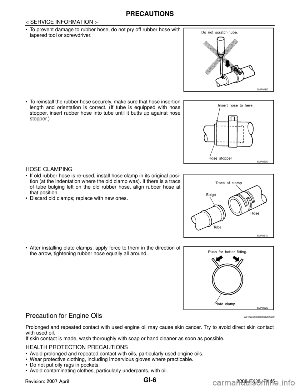
To prevent damage to rubber hose, do not pry off rubber hose withtapered tool or screwdriver.
To reinstall the rubber hose securely, make sure that hose insertion length and orientation is correct. (If tube is equipped with hose
stopper, insert rubber hose into tube until it butts up against hose
stopper.)
HOSE CLAMPING
If old rubber hose is re-used, install hose clamp in its original posi-tion (at the indentation where the old clamp was). If there is a trace
of tube bulging left on the old rubber hose, align rubber hose at
that position.
Discard old clamps; replace with new ones.
After installing plate clamps, apply force to them in the direction of the arrow, tightening rubber hose equally all around.
Precaution for Engine OilsINFOID:0000000001325660
Prolonged and repeated contact with used engine oil may cause skin cancer. Try to avoid direct skin contact
with used oil.
If skin contact is made, wash thoroughly with soap or hand cleaner as soon as possible.
HEALTH PROTECTION PRECAUTIONS
Avoid prolonged and repeated contact with oils, particularly used engine oils.
Wear protective clothing, including impervious gloves where practicable.
Do not put oily rags in pockets.
Avoid contaminating clothes, pa rticularly underpants, with oil.
SMA019D
SMA020D
SMA021D
SMA022D
3AA93ABC3ACD3AC03ACA3AC03AC63AC53A913A773A893A873A873A8E3A773A983AC73AC93AC03AC3
3A893A873A873A8F3A773A9D3AAF3A8A3A8C3A863A9D3AAF3A8B3A8C