installation INFINITI FX35 2008 Service Manual
[x] Cancel search | Manufacturer: INFINITI, Model Year: 2008, Model line: FX35, Model: INFINITI FX35 2008Pages: 3924, PDF Size: 81.37 MB
Page 2453 of 3924

EI-16
< SERVICE INFORMATION >
FRONT BUMPER
12. Remove nuts of bumper stay, and remove bumper stay. Removenuts with power tool.
13. Remove nuts of front bumper guard bar, and remove front bumper guard bar. Remove nuts with power tool.
14. Remove fog lamps located in bumper fascia. Refer to LT-76,
"Removal and Installation".
INSTALLATION
Install in the reverse order of removal.
NOTE:
After installation, adjust the clearance.
REMOVAL AND INSTALLATION OF FILLET MOLDING
Removal
1. Remove screws of fillet molding.
2. Remove clips of fillet molding.
3. Remove fillet molding.
Installation
1. Clean adhesive portion of front fender with white gasoline.
2. Strip pattern from the new double adhesive tape and paste on front fender.
3. Fillet molding assembly hold with front fender.
REMOVAL AND INSTALLATION OF BUMPER CENTER MOLDING
Removal
1. Remove front bumper fascia. Refer to EI-15, "Removal and Installation".
2. Remove bumper center molding mounting nuts.
3. Disengage plastic pawls from bumper fascia.
4. Remove bumper center molding.
Installation
Install in the reverse order of removal.
PIIA4339E
Portion Clearance
Front bumper – Front grille A – A 0.5 – 3.5 mm (0.020 – 0.138 in)
Front bumper – Headlamp B – B 1.5 – 4.5 mm (0.059 – 0.177 in)
Front bumper – Front fender C – C 0.0 – 0.5 mm (0.000 – 0.020 in)
PIIA4350E
3AA93ABC3ACD3AC03ACA3AC03AC63AC53A913A773A893A873A873A8E3A773A983AC73AC93AC03AC3
3A893A873A873A8F3A773A9D3AAF3A8A3A8C3A863A9D3AAF3A8B3A8C
Page 2455 of 3924
EI-18
< SERVICE INFORMATION >
REAR BUMPER
Removal and Installation
INFOID:0000000001529396
CAUTION:
Bumper fascia is made of resin. Do not apply strong force to it, and be careful to prevent contact with
oil.
REMOVAL
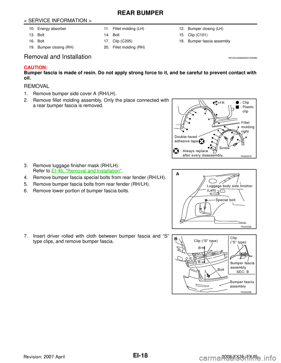
1. Remove bumper side cover A (RH/LH).
2. Remove fillet molding assembly. Only the place connected with a rear bumper fascia is removed.
3. Remove luggage finisher mask (RH/LH). Refer to EI-46, "
Removal and Installation".
4. Remove bumper fascia special bolts from rear fender (RH/LH).
5. Remove bumper fascia bolts from rear fender (RH/LH).
6. Remove lower portion of bumper fascia bolts.
7. Insert driver rolled with cloth between bumper fascia and “S” type clips, and remove bumper fascia.
10. Energy absorber 11. Fillet molding (LH) 12. Bumper closing (LH)
13. Bolt 14. Bolt 15. Clip (C101)
16. Bolt 17. Clip (C205) 18. Bumper fascia assembly
19. Bumper closing (RH) 20. Fillet molding (RH)
PIIA4347E
PIIA4334E
PIIA4335E
3AA93ABC3ACD3AC03ACA3AC03AC63AC53A913A773A893A873A873A8E3A773A983AC73AC93AC03AC3
3A893A873A873A8F3A773A9D3AAF3A8A3A8C3A863A9D3AAF3A8B3A8C
Page 2456 of 3924
REAR BUMPEREI-19
< SERVICE INFORMATION >
C
DE
F
G H
J
K L
M A
B
EI
N
O P
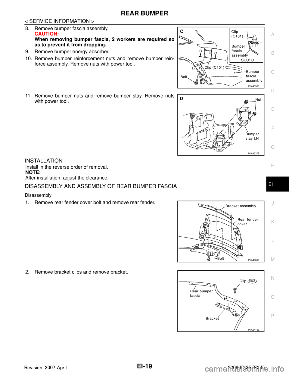
8. Remove bumper fascia assembly. CAUTION:
When removing bumper fasci a, 2 workers are required so
as to prevent it from dropping.
9. Remove bumper energy absorber.
10. Remove bumper reinforcement nuts and remove bumper rein- force assembly. Remove nuts with power tool.
11. Remove bumper nuts and remove bumper stay. Remove nuts with power tool.
INSTALLATION
Install in the reverse order of removal.
NOTE:
After installation, adjust the clearance.
DISASSEMBLY AND ASSEMBLY OF REAR BUMPER FASCIA
Disassembly
1. Remove rear fender cover bolt and remove rear fender.
2. Remove bracket clips and remove bracket.
PIIA4336E
PIIA4337E
PIIA4960E
PIIA6416E
3AA93ABC3ACD3AC03ACA3AC03AC63AC53A913A773A893A873A873A8E3A773A983AC73AC93AC03AC3
3A893A873A873A8F3A773A9D3AAF3A8A3A8C3A863A9D3AAF3A8B3A8C
Page 2457 of 3924
EI-20
< SERVICE INFORMATION >
REAR BUMPER
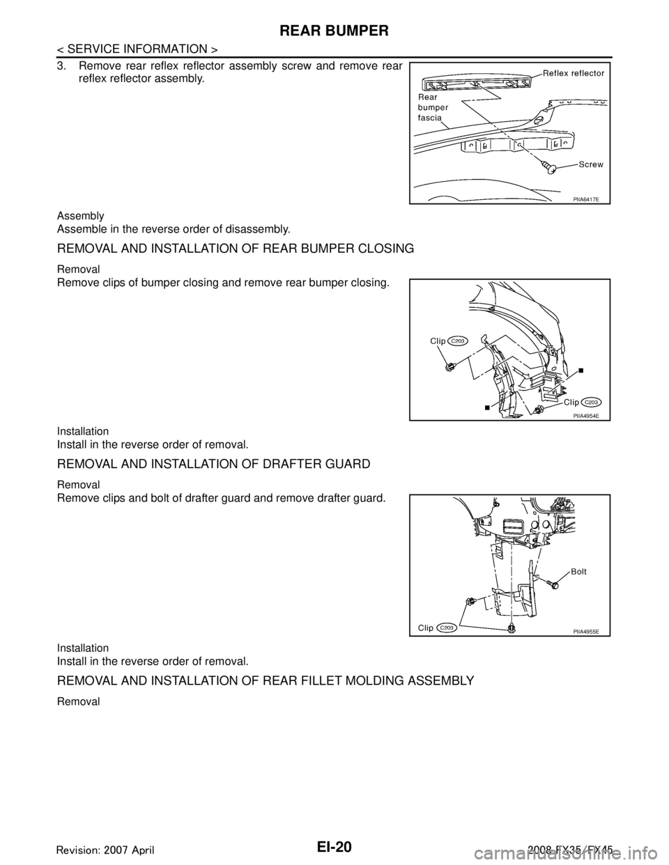
3. Remove rear reflex reflector assembly screw and remove rearreflex reflector assembly.
Assembly
Assemble in the reverse order of disassembly.
REMOVAL AND INSTALLATION OF REAR BUMPER CLOSING
Removal
Remove clips of bumper closing and remove rear bumper closing.
Installation
Install in the reverse order of removal.
REMOVAL AND INSTALLATION OF DRAFTER GUARD
Removal
Remove clips and bolt of drafter guard and remove drafter guard.
Installation
Install in the reverse order of removal.
REMOVAL AND INSTALLATION OF REAR FILLET MOLDING ASSEMBLY
Removal
PIIA6417E
PIIA4954E
PIIA4955E
3AA93ABC3ACD3AC03ACA3AC03AC63AC53A913A773A893A873A873A8E3A773A983AC73AC93AC03AC3
3A893A873A873A8F3A773A9D3AAF3A8A3A8C3A863A9D3AAF3A8B3A8C
Page 2458 of 3924

REAR BUMPEREI-21
< SERVICE INFORMATION >
C
DE
F
G H
J
K L
M A
B
EI
N
O P
1. Remove bolts of fillet molding assembly.
2. Remove clips of fillet molding assembly.
3. Remove fillet molding assembly.
Installation
1. Clean adhesive portion of rear fender with white gasoline.
2. Strip pattern from the new double adhesive tape and paste on rear fender.
3. Fillet molding assembly hold with rear fender.
PIIA4347E
3AA93ABC3ACD3AC03ACA3AC03AC63AC53A913A773A893A873A873A8E3A773A983AC73AC93AC03AC3
3A893A873A873A8F3A773A9D3AAF3A8A3A8C3A863A9D3AAF3A8B3A8C
Page 2459 of 3924
EI-22
< SERVICE INFORMATION >
FRONT GRILLE
FRONT GRILLE
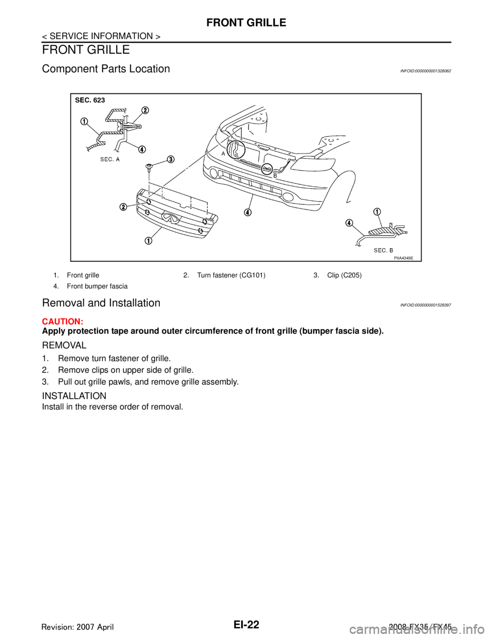
Component Parts LocationINFOID:0000000001328062
Removal and InstallationINFOID:0000000001529397
CAUTION:
Apply protection tape around outer circumference of front grille (bumper fascia side).
REMOVAL
1. Remove turn fastener of grille.
2. Remove clips on upper side of grille.
3. Pull out grille pawls, and remove grille assembly.
INSTALLATION
Install in the reverse order of removal.
1. Front grille 2. Turn fastener (CG101) 3. Clip (C205)
4. Front bumper fascia
PIIA4349E
3AA93ABC3ACD3AC03ACA3AC03AC63AC53A913A773A893A873A873A8E3A773A983AC73AC93AC03AC3
3A893A873A873A8F3A773A9D3AAF3A8A3A8C3A863A9D3AAF3A8B3A8C
Page 2460 of 3924
COWL TOPEI-23
< SERVICE INFORMATION >
C
DE
F
G H
J
K L
M A
B
EI
N
O P
COWL TOP
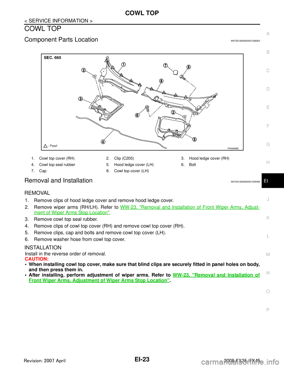
Component Parts LocationINFOID:0000000001328063
Removal and InstallationINFOID:0000000001529398
REMOVAL
1. Remove clips of hood ledge cover and remove hood ledge cover.
2. Remove wiper arms (RH/LH). Refer to WW-23, "
Removal and Installation of Front Wiper Arms, Adjust-
ment of Wiper Arms Stop Location".
3. Remove cowl top seal rubber.
4. Remove clips of cowl top cover (RH) and remove cowl top cover (RH).
5. Remove clips, cap and bolts and remove cowl top cover (LH).
6. Remove washer hose from cowl top cover.
INSTALLATION
Install in the reverse order of removal.
CAUTION:
When installing cowl top cover, m ake sure that blind clips are securely fitted in panel holes on body,
and then press them in.
After installing, perform adjust ment of wiper arms. Refer to WW-23, "
Removal and Installation of
Front Wiper Arms, Adjustment of Wiper Arms Stop Location".
1. Cowl top cover (RH) 2. Clip (C205) 3. Hood ledge cover (RH)
4. Cowl top seal rubber 5. Hood ledge cover (LH) 6. Bolt
7. Cap 8. Cowl top cover (LH)
PIIA4946E
3AA93ABC3ACD3AC03ACA3AC03AC63AC53A913A773A893A873A873A8E3A773A983AC73AC93AC03AC3
3A893A873A873A8F3A773A9D3AAF3A8A3A8C3A863A9D3AAF3A8B3A8C
Page 2461 of 3924
EI-24
< SERVICE INFORMATION >
FENDER PROTECTOR
FENDER PROTECTOR
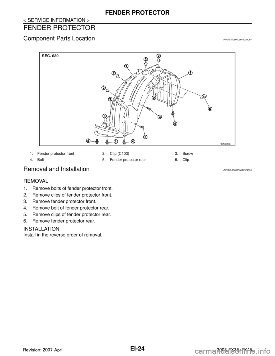
Component Parts LocationINFOID:0000000001328064
Removal and InstallationINFOID:0000000001529399
REMOVAL
1. Remove bolts of fender protector front.
2. Remove clips of fender protector front.
3. Remove fender protector front.
4. Remove bolt of fender protector rear.
5. Remove clips of fender protector rear.
6. Remove fender protector rear.
INSTALLATION
Install in the reverse order of removal.
1. Fender protector front 2. Clip (C103) 3. Screw
4. Bolt 5. Fender protector rear 6. Clip
PIIA4326E
3AA93ABC3ACD3AC03ACA3AC03AC63AC53A913A773A893A873A873A8E3A773A983AC73AC93AC03AC3
3A893A873A873A8F3A773A9D3AAF3A8A3A8C3A863A9D3AAF3A8B3A8C
Page 2462 of 3924
DOOR OUTSIDE MOLDINGEI-25
< SERVICE INFORMATION >
C
DE
F
G H
J
K L
M A
B
EI
N
O P
DOOR OUTSIDE MOLDING
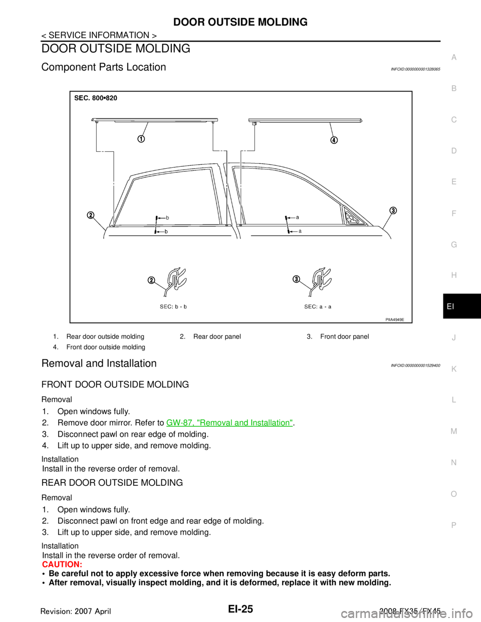
Component Parts LocationINFOID:0000000001328065
Removal and InstallationINFOID:0000000001529400
FRONT DOOR OUTSIDE MOLDING
Removal
1. Open windows fully.
2. Remove door mirror. Refer to GW-87, "
Removal and Installation".
3. Disconnect pawl on rear edge of molding.
4. Lift up to upper side, and remove molding.
Installation
Install in the reverse order of removal.
REAR DOOR OUTSIDE MOLDING
Removal
1. Open windows fully.
2. Disconnect pawl on front edge and rear edge of molding.
3. Lift up to upper side, and remove molding.
Installation
Install in the reverse order of removal.
CAUTION:
Be careful not to apply excessive force when removing because it is easy deform parts.
After removal, visually inspect molding, and it is deformed, replace it with new molding.
1. Rear door outside molding 2. Rear door panel 3. Front door panel
4. Front door outside molding
PIIA4949E
3AA93ABC3ACD3AC03ACA3AC03AC63AC53A913A773A893A873A873A8E3A773A983AC73AC93AC03AC3
3A893A873A873A8F3A773A9D3AAF3A8A3A8C3A863A9D3AAF3A8B3A8C
Page 2463 of 3924
EI-26
< SERVICE INFORMATION >
DOOR OUTSIDE LOWER MOLDING
DOOR OUTSIDE LOWER MOLDING
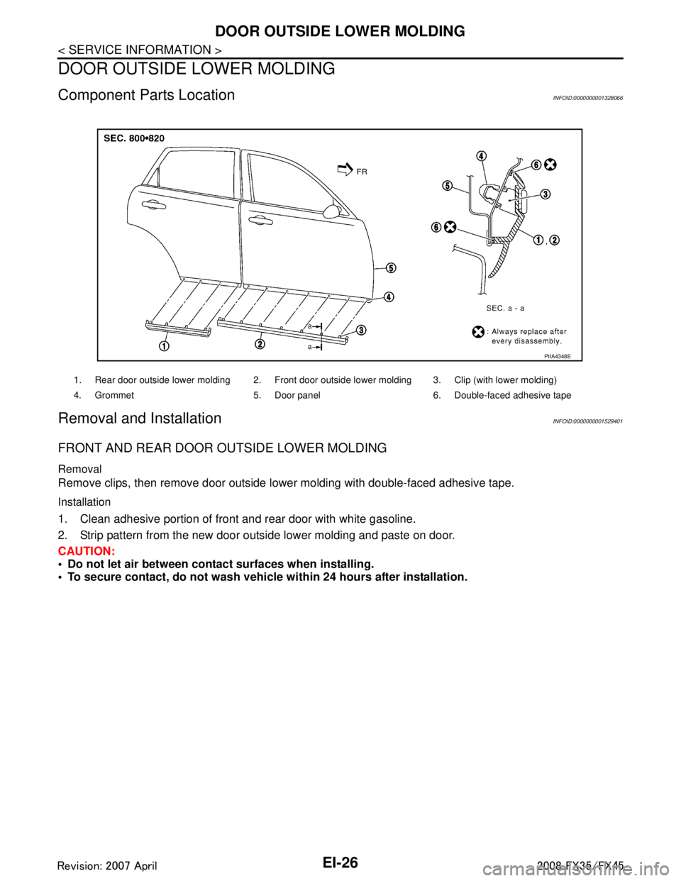
Component Parts LocationINFOID:0000000001328066
Removal and InstallationINFOID:0000000001529401
FRONT AND REAR DOOR OUTSIDE LOWER MOLDING
Removal
Remove clips, then remove door outside lower molding with double-faced adhesive tape.
Installation
1. Clean adhesive portion of front and rear door with white gasoline.
2. Strip pattern from the new door outside lower molding and paste on door.
CAUTION:
Do not let air between contact surfaces when installing.
To secure contact, do not wash vehicle within 24 hours after installation.
1. Rear door outside lower molding 2. Front door outside lower molding 3. Clip (with lower molding)
4. Grommet 5. Door panel 6. Double-faced adhesive tape
PIIA4348E
3AA93ABC3ACD3AC03ACA3AC03AC63AC53A913A773A893A873A873A8E3A773A983AC73AC93AC03AC3
3A893A873A873A8F3A773A9D3AAF3A8A3A8C3A863A9D3AAF3A8B3A8C