lock INFINITI FX35 2008 Service Manual
[x] Cancel search | Manufacturer: INFINITI, Model Year: 2008, Model line: FX35, Model: INFINITI FX35 2008Pages: 3924, PDF Size: 81.37 MB
Page 3590 of 3924

SHOCK ABSORBERRSU-9
< SERVICE INFORMATION >
C
DF
G H
I
J
K L
M A
B
RSU
N
O P
SHOCK ABSORBER
Removal and InstallationINFOID:0000000001327555
REMOVAL
1. Remove tires from vehicle with power tool.
2. Set jack under rear lower link.
3. Remove fixing bolt in lower side of shock absorber assembly with power tool.
4. Remove fixing nuts in upper side of shock absorber assembly with power tool and remove shock absorber assembly from
vehicle.
INSPECTION AFTER REMOVAL
Check shock absorber assembly for deformation, cracks, or damage, and replace if necessary.
Check piston rod for damage, uneven wear, or distortion, and replace if necessary.
Check welded and sealed areas for oil leakage, and replace if necessary.
INSTALLATION
Refer to RSU-6, "Removal and Installation" for tightening torque. Install in the reverse order of removal.
NOTE:
Refer to component parts location and do not reuse non-reusable parts.
Perform final tightening of shock absorber assembly lower side (rubber b\
ushing) under unladen conditions
with tires on level ground. Check wheel alignment. Refer to RSU-18, "
Wheel Alignment (Unladen*)".
After adjusting wheel alignment, adjust neutral position of steering angle sensor. Refer to BRC-8, "
Adjust-
ment of Steering Angle Sensor Neutral Position".
Disassembly and AssemblyINFOID:0000000001327556
DISASSEMBLY
CAUTION:
Make sure piston rod on shock absorber is not damaged when removing components from shock
absorber.
1. Remove mounting seal fr om mounting seal bracket.
2. Wrap a shop cloth around lower side of shock absorber and fix it in a vise. CAUTION:
Do not set the cylindrical part of shock absorber in vise.
3. Fix piston rod with hexagon wrench, and remove piston rod lock nut.
4. Remove mounting seal bracke t, bushing, distance tube, bound
bumper cover and bound bumper from shock absorber.
INSPECTION AFTER DISASSEMBLY
Bound Bumper and Bushing
FA-0274D
SEIA0366E
3AA93ABC3ACD3AC03ACA3AC03AC63AC53A913A773A893A873A873A8E3A773A983AC73AC93AC03AC3
3A893A873A873A8F3A773A9D3AAF3A8A3A8C3A863A9D3AAF3A8B3A8C
Page 3603 of 3924

SB-4
< SERVICE INFORMATION >
SEAT BELTS
2. Remove the anchor bolt.
3. Remove the seat cushion outer finisher cover, and remove the anchor bolt.NOTE:
Set the front and rear cushion lifter to the lower position.
4. Disconnect the belt tension sensor connector (passenger side only).
5. Remove the center pillar upper and lower garnish. Refer to EI-38, "
Component Parts Location".
6. Disconnect the seat belt pre-tensioner connector.
CAUTION:
For installing/removing seat belt pre-tensioner connector, insert thin screwdriver wrapped in tape into notch, lift lock
and remove connector.
Install connector with lock ra ised, and push lock into connec-
tor.
7. Remove the seat belt pre-tensioner retractor fixi ng screw and anchor bolt, and then remove the seat belt
retractor.
INSTALLATION OF FRONT SEAT BELT RETRACTOR
CAUTION:
Before servicing SRS, turn the igni tion switch OFF, disconnect both battery cables and wait at least 3
minutes.
Install in the reverse order of removal.
REMOVAL OF FRONT SEAT BELT BUCKLE
1. Remove the front seat. Refer to SE-89, "Removal and Installation".
2. Disconnect the buckle switch connector.
3. Remove the anchor bolt, and remove the buckle.
INSTALLATION OF FRONT SEAT BELT BUCKLE
Install in the reverse order of removal.
PHIA0341E
PHIA0346E
3AA93ABC3ACD3AC03ACA3AC03AC63AC53A913A773A893A873A873A8E3A773A983AC73AC93AC03AC3
3A893A873A873A8F3A773A9D3AAF3A8A3A8C3A863A9D3AAF3A8B3A8C
Page 3606 of 3924

SEAT BELTSSB-7
< SERVICE INFORMATION >
C
DE
F
G
I
J
K L
M A
B
SB
N
O P
7. Repeat steps above as necessary to check the other seat belts.
SEAT BELT RETRACTOR ON-VEHICLE INSPECTION
Emergency Locking Retractors (ELR) and Automatic Locking Retractors (ALR)
NOTE:
All seat belt retractors are of the Emergency Locki ng Retractors (ELR) type. In an emergency (sudden stop)
the retractor will lock and prevent the webbing from extending any further. All 3-point type seat belt retractors
except the driver's seat belt also have an Automati c Locking Retractors (ALR) mode. The ALR mode (also
called child restraint mode) is used when installing child seats. The ALR mode is activated when the seat belt
is fully extended. When the webbing is then retracted part ially, the ALR mode automatically locks the seat belt
in a specific position so the webbi ng cannot be extended any further. To c ancel the ALR mode, allow the seat
belt to fully wind back into the retractor.
Check the seat belt retractors using the following test(s ) to determine if a retractor assembly is operating prop-
erly.
Stationary Inspection for ELR Function
Grasp the shoulder webbing and pull forward quickly. The retractor should lock and prevent the belt from
extending further.
Stationary Inspection for ALR Function
1. Pull out entire length of seat belt from retractor until a click is heard.
2. Retract the webbing partially. A clicking noise should be heard as the webbing retracts indicating that the
retractor is in the Automatic Locking Retractor (ALR) mode.
3. Grasp the seat belt and try to pull out the retracto r. The webbing must lock and not extend any further. If
necessary replace the retractor assembly.
4. Allow the entire length of the webbing to retract to cancel the automatic locking mode.
Moving Inspection for ELR Function
WARNING:
Perform the following test in a safe, open area clear of other vehicles and obstructions (for example, a
large, empty parking lot). Road surface must be p aved and dry. DO NOT perform the following test on
wet or gravel roads or on public streets and highways. This could result in an accident and serious
personal injury. The driver and passenger must be prepared to brace themselves in the event the
retractor does not lock.
1. Fasten driver's seat belt. Buckle a passenger in to the seat for the belt that is to be tested.
2. Proceed to the designated safe area.
3. Drive the vehicle at approximately 16 km/h ( 10 MPH). Notify any passengers of a pending sudden stop.
The driver and passenger must be prepared to brace t hemselves in the event the retractor does not lock.
Apply brakes firmly and make a very hard stop.
During stop, seat belts should lock and not be extended. If the seat belt retractor assembly does not lock, per-
form the retractor off-vehicle inspection.
SEAT BELT RETRACTOR OFF-VEHICLE INSPECTION
1. Remove the seat belt retractor assembly.
3AA93ABC3ACD3AC03ACA3AC03AC63AC53A913A773A893A873A873A8E3A773A983AC73AC93AC03AC3
3A893A873A873A8F3A773A9D3AAF3A8A3A8C3A863A9D3AAF3A8B3A8C
Page 3607 of 3924

SB-8
< SERVICE INFORMATION >
SEAT BELTS
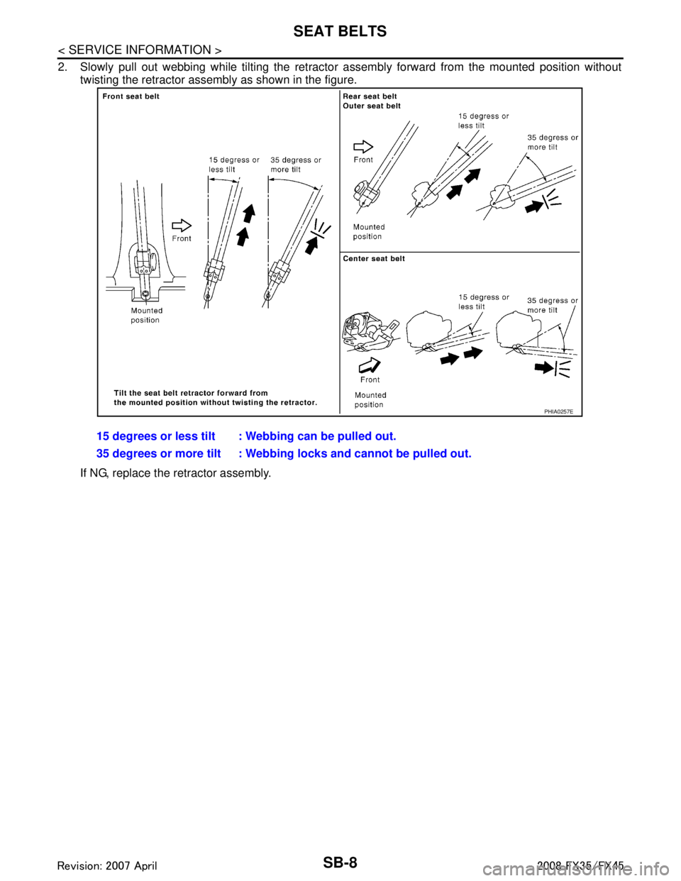
2. Slowly pull out webbing while tilting the retractor assembly forward from the mounted position without
twisting the retractor assembly as shown in the figure.
If NG, replace the retractor assembly. 15 degrees or less tilt : Webbing can be pulled out.
35 degrees or more tilt : Webbing
locks and cannot be pulled out.
PHIA0257E
3AA93ABC3ACD3AC03ACA3AC03AC63AC53A913A773A893A873A873A8E3A773A983AC73AC93AC03AC3
3A893A873A873A8F3A773A9D3AAF3A8A3A8C3A863A9D3AAF3A8B3A8C
Page 3617 of 3924

SC-8
< SERVICE INFORMATION >
STARTING SYSTEM
STARTING SYSTEM
System DescriptionINFOID:0000000001328246
Power is supplied at all times
through 40A fusible link (letter F, located in the fuse and fusible link block)
to ignition switch terminal 1,
through 15A fuse (No. 78, located in the IPDM E/R)
to CPU of IPDM E/R,
through 10A fuse (No. 71, located in the IPDM E/R)
to CPU of IPDM E/R.
When the selector lever in the P or N position, power is supplied
from TCM, and through A/T assembly terminal 9
to IPDM E/R terminal 53.
Ground is supplied
to IPDM E/R terminals 38, 50 and 60
from grounds E21, E50 and E51.
With the ignition switch in the START position, and provided that the IPDM E/R receives a starter relay ON sig-
nal from the CAN lines, the IPDM E/ R is energized and power is supplied
from ignition switch terminal 5
to IPDM E/R terminal 4 and
through IPDM E/R terminal 3
to starter motor terminal 1.
The starter motor plunger closes and provides a clos ed circuit between the battery and starter motor. The
starter motor is grounded to the engine block. With power and ground supplied, cranking occurs and the
engine starts.
3AA93ABC3ACD3AC03ACA3AC03AC63AC53A913A773A893A873A873A8E3A773A983AC73AC93AC03AC3
3A893A873A873A8F3A773A9D3AAF3A8A3A8C3A863A9D3AAF3A8B3A8C
Page 3622 of 3924

STARTING SYSTEMSC-13
< SERVICE INFORMATION >
C
DE
F
G H
I
J
L
M A
B
SC
N
O P
4. Check voltage between starter motor harness connector E312 (VK45DE) or F33 (VQ35DE) terminal 1 and ground.
OK or NG
OK >> “S” connector circuit is OK. Further inspection neces- sary. Refer to SC-10, "
Trouble Diagnosis with Starting/
Charging System Tester (Starting)".
NG >> Check the following.
40A fusible link (letter F, located in fuse and fusible link box)
Ignition switch
Starter relay (within the IPDM E/R)
Harness for open or short
MINIMUM SPECIFICATION OF CRANKING VO LTAGE REFERENCING COOLANT TEMPERA-
TURE
Removal and Installation (VK45DE Engine Models)INFOID:0000000001328249
REMOVAL
1. Disconnect the battery cable from the negative terminal.
2. Remove engine front and rear undercover, using power tools. 1 – Ground
When ignition switch is in
START position
: Battery voltage
PKIB8796E
Engine coolant temperature Voltage [V]
− 30 °C to −20 °C ( −22 °F to −4 °F) 8.4
− 19 °C to −10 °C ( −2 °F to 14 °F) 8.9
− 9 °C to 0 °C (16 °F to 32 °F) 9.3
More than 1 °C (More than 34 °F) 9.7
1. Starter motor 2. Starter motor mounting bolt 3. B terminal harness
4. B terminal nut 5. S connector 6. Cylinder block
: N·m (kg-m, ft-lb) : N·m (k g-m, ft-in) : Engine front
PKID1545E
3AA93ABC3ACD3AC03ACA3AC03AC63AC53A913A773A893A873A873A8E3A773A983AC73AC93AC03AC3
3A893A873A873A8F3A773A9D3AAF3A8A3A8C3A863A9D3AAF3A8B3A8C
Page 3627 of 3924

SC-18
< SERVICE INFORMATION >
STARTING SYSTEM
Inspection After Disassembly
INFOID:0000000001328253
PINION/CLUTCH CHECK
1. Inspect pinion teeth. Replace pinion if teeth are worn or damaged. (Also check condition of ring gear teeth.)
2. Inspect reduction gear teeth. Replace reduction gear if teeth are worn or dam aged. (Also check condition of armature shaft gear
teeth.)
3. Check to see if pinion locks in one directi on and rotates smoothly in the opposite direction.
If it locks or rotates in both directions , or unusual resistance is evident, replace.
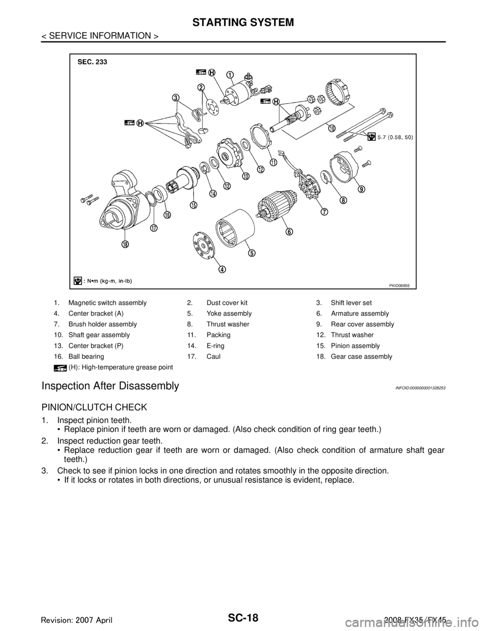
1. Magnetic switch assembly 2. Dust cover kit 3. Shift lever set
4. Center bracket (A) 5. Yoke assembly 6. Armature assembly
7. Brush holder assembly 8. Thrust washer 9. Rear cover assembly
10. Shaft gear assembly 11. Packing 12. Thrust washer
13. Center bracket (P) 14. E-ring 15. Pinion assembly
16. Ball bearing 17. Caul 18. Gear case assembly
(H): High-temperatu re grease point
PKID0695E
3AA93ABC3ACD3AC03ACA3AC03AC63AC53A913A773A893A873A873A8E3A773A983AC73AC93AC03AC3
3A893A873A873A8F3A773A9D3AAF3A8A3A8C3A863A9D3AAF3A8B3A8C
Page 3628 of 3924

CHARGING SYSTEMSC-19
< SERVICE INFORMATION >
C
DE
F
G H
I
J
L
M A
B
SC
N
O P
CHARGING SYSTEM
System DescriptionINFOID:0000000001328254
The alternator provides DC voltage to operate the vehi cle's electrical system and to keep the battery charged.
The voltage output is controlled by the IC regulator.
Power is supplied at all times
through 10A fuse (No. 33, located in the fuse and fusible link block)
to alternator terminal 4 (“S” terminal).
“B” Terminal supplies power to charge the battery and oper ate the vehicle's electrical system. Output voltage
is controlled by the IC regulator at terminal 4 (“S” terminal) detecting the input voltage.
The charging circuit is protected by the 120A fusible link (VK45DE and VQ35DE AWD).
The alternator is grounded to the engine block.
With the ignition switch in the ON or START position, power is supplied
through 10A fuse [No. 14, located in the fuse block (J/B)]
to combination meter terminal 7 for the charge warning lamp.
Ground is supplied
to combination meter terminal 2
through alternator terminal 3 (“L” terminal)
to alternator terminal 2 (“E” terminal) (VK45DE) or through case ground (VQ35DE)
through ground E304 (VK45DE).
With power and ground supplied, the charge warning lamp will illuminate. When the alternator is providing suf-
ficient voltage with the engine running, the ground is opened and the charge warning lamp will go off.
If the charge warning lamp illuminates with the engine running, a malfunction is indicated.
MALFUNCTION INDICATOR
The IC regulator warning function activates to illumi nate charge warning lamp, if any of the following symp-
toms occur while alternator is operating:
Excessive voltage is produced.
No voltage is produced.
3AA93ABC3ACD3AC03ACA3AC03AC63AC53A913A773A893A873A873A8E3A773A983AC73AC93AC03AC3
3A893A873A873A8F3A773A9D3AAF3A8A3A8C3A863A9D3AAF3A8B3A8C
Page 3645 of 3924

SE-6
< SERVICE INFORMATION >
SQUEAK AND RATTLE TROUBLE DIAGNOSES
SQUEAK AND RATTLE TROUBLE DIAGNOSES
Work FlowINFOID:0000000001328094
CUSTOMER INTERVIEW
Interview the customer if possible, to determine the c onditions that exist when the noise occurs. Use the Diag-
nostic Worksheet during the interview to document the facts and conditions when the noise occurs and any
customer's comments; refer to SE-10, "
Diagnostic Worksheet". This information is necessary to duplicate the
conditions that exist when the noise occurs.
The customer may not be able to provide a detailed description or the location of the noise. Attempt to obtain all the facts and conditions that exist w hen the noise occurs (or does not occur).
If there is more than one noise in the vehicle, be sure to diagnose and repair the noise that the customer is
concerned about. This can be accomplished by test driving the vehicle with the customer.
After identifying the type of noise, isolate the noise in terms of its characteristics. The noise characteristics
are provided so the customer, service adviser and technician are all speaking the same language when
defining the noise.
Squeak —(Like tennis shoes on a clean floor)
Squeak characteristics include the light contact/fa st movement/brought on by road conditions/hard sur-
faces=higher pitch noise/softer surfaces=l ower pitch noises/edge to surface=chirping
Creak—(Like walking on an old wooden floor)
Creak characteristics include firm contact/slow mo vement/twisting with a rotational movement/pitch depen-
dent on materials/often brought on by activity.
Rattle—(Like shaking a baby rattle)
Rattle characteristics include the fast repeated contac t/vibration or similar movement/loose parts/missing
clip or fastener/incorrect clearance.
Knock —(Like a knock on a door)
Knock characteristics include hollow sounding/someti mes repeating/often brought on by driver action.
Tick—(Like a clock second hand) Tick characteristics include gentle contacting of light materials/loose components/can be caused by driver
action or road conditions.
Thump—(Heavy, muffled knock noise) Thump characteristics include softer k nock/dead sound often brought on by activity.
Buzz—(Like a bumble bee)
Buzz characteristics include hi gh frequency rattle/firm contact.
Often the degree of acceptable noise level will vary depending upon the person. A noise that you may judge as acceptable may be very irritating to the customer.
Weather conditions, especially humidity and temperat ure, may have a great effect on noise level.
DUPLICATE THE NOISE AND TEST DRIVE
If possible, drive the vehicle with the customer until the noise is duplicated. Note any additional information on
the Diagnostic Worksheet regarding the conditions or lo cation of the noise. This information can be used to
duplicate the same conditions when you confirm the repair.
SBT842
3AA93ABC3ACD3AC03ACA3AC03AC63AC53A913A773A893A873A873A8E3A773A983AC73AC93AC03AC3
3A893A873A873A8F3A773A9D3AAF3A8A3A8C3A863A9D3AAF3A8B3A8C
Page 3646 of 3924

SQUEAK AND RATTLE TROUBLE DIAGNOSESSE-7
< SERVICE INFORMATION >
C
DE
F
G H
J
K L
M A
B
SE
N
O P
If the noise can be duplicated easily during the test drive, to help identify the source of the noise, try to dupli-
cate the noise with the vehicle stopped by doing one or all of the following:
1) Close a door.
2) Tap or push/pull around the area where the noise appears to be coming from.
3) Rev the engine.
4) Use a floor jack to recreate vehicle “twist”.
5) At idle, apply engine load (electrical load, half- clutch on M/T model, drive position on A/T model).
6) Raise the vehicle on a hoist and hit a tire with a rubber hammer.
Drive the vehicle and attempt to duplicate the conditions the customer states exist when the noise occurs.
If it is difficult to duplicate the noise, drive the vehicle slowly on an undulating or rough road to stress the vehicle body.
CHECK RELATED SERVICE BULLETINS
After verifying the customer concern or symptom, che ck ASIST for Technical Service Bulletins (TSBs) related
to that concern or symptom.
If a TSB relates to the symptom, follow the procedure to repair the noise.
LOCATE THE NOISE AND IDENTIFY THE ROOT CAUSE
1. Narrow down the noise to a general area. To help pinpoint the source of the noise, use a listening tool (Chassis Ear: J-39570,Engine Ear and mechanics stethoscope).
2. Narrow down the noise to a more specific area and identify the cause of the noise by:
removing the components in the area that you suspect the noise is coming from. Do not use too much force when removing clips and fasteners, otherwise clips and fastener can be broken
or lost during the repair, resulting in the creation of new noise.
tapping or pushing/pulling the component that you suspect is causing the noise.
Do not tap or push/pull the component with excessive force, otherwise the noise will be eliminated only tem-
porarily.
feeling for a vibration with your hand by touching the component(s) that you suspect is (are) causing the
noise.
placing a piece of paper between components that you suspect are causing the noise.
looking for loose components and contact marks. Refer to SE-8, "
Generic Squeak and Rattle Troubleshooting".
REPAIR THE CAUSE
If the cause is a loose component, tighten the component securely.
If the cause is insufficient clearance between components:
- separate components by repositioning or loos ening and retightening the component, if possible.
- insulate components with a suitable insulator such as urethane pads, foam blocks, felt cloth tape or urethane tape. A Nissan Squeak and Rattle Kit (J-43980) is av ailable through your authorized Nissan Parts Depart-
ment.
CAUTION:
Do not use excessive force as many components are constructed of plastic and may be damaged.
NOTE:
Always check with the Parts Department for the latest parts information.
The following materials are contained in the Niss an Squeak and Rattle Kit (J-43980). Each item can be
ordered separately as needed.
URETHANE PADS [1.5 mm (0.059 in) thick]
Insulates connectors, harness, etc.
76268-9E005: 100 × 135 mm (3.94 × 5.31 in)/76884-71L01: 60 × 85 mm (2.36 × 3.35 in)/76884-71L02:15 ×
25 mm (0.59 × 0.98 in)
INSULATOR (Foam blocks)
Insulates components from contact. Can be used to fill space behind a panel.
73982-9E000: 45 mm (1.77 in) thick, 50 × 50 mm (1.97 × 1.97 in)/73982-50Y00: 10 mm (0.39 in) thick, 50
× 50 mm (1.97 × 1.97 in)
INSULATOR (Light foam block)
80845-71L00: 30 mm (1.18 in) thick, 30 × 50 mm (1.18 × 1.97 in)
FELT CLOTHTAPE
Used to insulate where movement does not occur. Ideal for instrument panel applications.
68370-4B000: 15 × 25 mm (0.59 × 0.98 in) pad/68239-13E00: 5 mm (0.20 in) wide tape roll The following
materials, not found in the kit, can also be used to repair squeaks and rattles.
UHMW(TEFLON) TAPE
3AA93ABC3ACD3AC03ACA3AC03AC63AC53A913A773A893A873A873A8E3A773A983AC73AC93AC03AC3
3A893A873A873A8F3A773A9D3AAF3A8A3A8C3A863A9D3AAF3A8B3A8C