torque INFINITI FX35 2008 Repair Manual
[x] Cancel search | Manufacturer: INFINITI, Model Year: 2008, Model line: FX35, Model: INFINITI FX35 2008Pages: 3924, PDF Size: 81.37 MB
Page 360 of 3924
REPAIR FOR COMPONENT PARTSAT-287
< SERVICE INFORMATION >
DE
F
G H
I
J
K L
M A
B
AT
N
O P
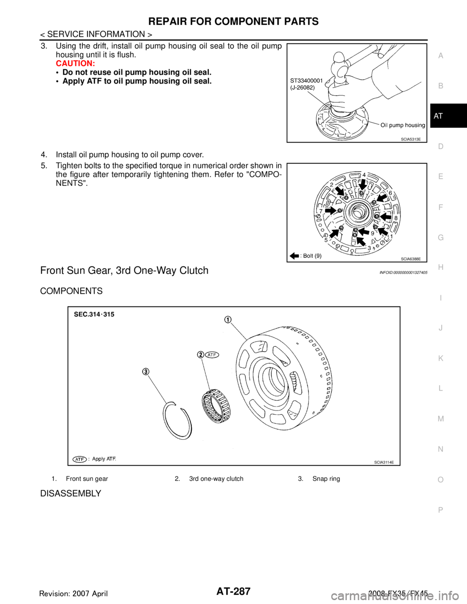
3. Using the drift, install oil pump housing oil seal to the oil pump housing until it is flush.
CAUTION:
Do not reuse oil pump housing oil seal.
Apply ATF to oil pump housing oil seal.
4. Install oil pump housing to oil pump cover.
5. Tighten bolts to the specified torque in numerical order shown in the figure after temporarily ti ghtening them. Refer to "COMPO-
NENTS".
Front Sun Gear, 3r d One-Way ClutchINFOID:0000000001327405
COMPONENTS
DISASSEMBLY
SCIA5313E
SCIA6388E
1. Front sun gear 2. 3rd one-way clutch 3. Snap ring
SCIA3114E
3AA93ABC3ACD3AC03ACA3AC03AC63AC53A913A773A893A873A873A8E3A773A983AC73AC93AC03AC3
3A893A873A873A8F3A773A9D3AAF3A8A3A8C3A863A9D3AAF3A8B3A8C
Page 379 of 3924
![INFINITI FX35 2008 Repair Manual
AT-306
< SERVICE INFORMATION >
ASSEMBLY
ASSEMBLY
Assembly (1)INFOID:0000000001327410
1. As shown in the figure, use a drift [commercial service tool: 22mm (0.87 in) dia.] to drive manual shaft oil se INFINITI FX35 2008 Repair Manual
AT-306
< SERVICE INFORMATION >
ASSEMBLY
ASSEMBLY
Assembly (1)INFOID:0000000001327410
1. As shown in the figure, use a drift [commercial service tool: 22mm (0.87 in) dia.] to drive manual shaft oil se](/img/42/57017/w960_57017-378.png)
AT-306
< SERVICE INFORMATION >
ASSEMBLY
ASSEMBLY
Assembly (1)INFOID:0000000001327410
1. As shown in the figure, use a drift [commercial service tool: 22mm (0.87 in) dia.] to drive manual shaft oil seals into the trans-
mission case until it is flush.
CAUTION:
Do not reuse manual shaft oil seals.
Apply ATF to manual shaft oil seals.
2. Install detent spring and spacer in transmission case, and then tighten detent spring and spacer mounting bolt to the specified
torque. Refer to AT-249, "
Component".
3. Install manual shaft to transmission case.
4. Install parking rod to manual plate.
SCIA5259E
SCIA5248E
SCIA5716E
SCIA5220E
3AA93ABC3ACD3AC03ACA3AC03AC63AC53A913A773A893A873A873A8E3A773A983AC73AC93AC03AC3
3A893A873A873A8F3A773A9D3AAF3A8A3A8C3A863A9D3AAF3A8B3A8C
Page 385 of 3924

AT-312
< SERVICE INFORMATION >
ASSEMBLY
24. Install revolution sensor to transmission case, and then tightenrevolution sensor mounting bolt to the specified torque. Refer to
AT-249, "
Component".
CAUTION:
Do not subject it to impact by dropping or hitting it.
Do not disassemble.
Do not allow metal filings, etc. to get on the sensor's front
edge magnetic area.
Do not place in an area affected by magnetism.
25. As shown in the figure, use the drift to drive rear oil seal into the rear extension (2WD models) or adapter case (AWD models)
until it is flush.
CAUTION:
Do not reuse rear oil seal.
Apply ATF to rear oil seal.
26. Install return spring to parking pawl. VQ35DE models
SCIA2320E
SCIA5477E
SCIA2445E
3AA93ABC3ACD3AC03ACA3AC03AC63AC53A913A773A893A873A873A8E3A773A983AC73AC93AC03AC3
3A893A873A873A8F3A773A9D3AAF3A8A3A8C3A863A9D3AAF3A8B3A8C
Page 388 of 3924
ASSEMBLYAT-315
< SERVICE INFORMATION >
DE
F
G H
I
J
K L
M A
B
AT
N
O P
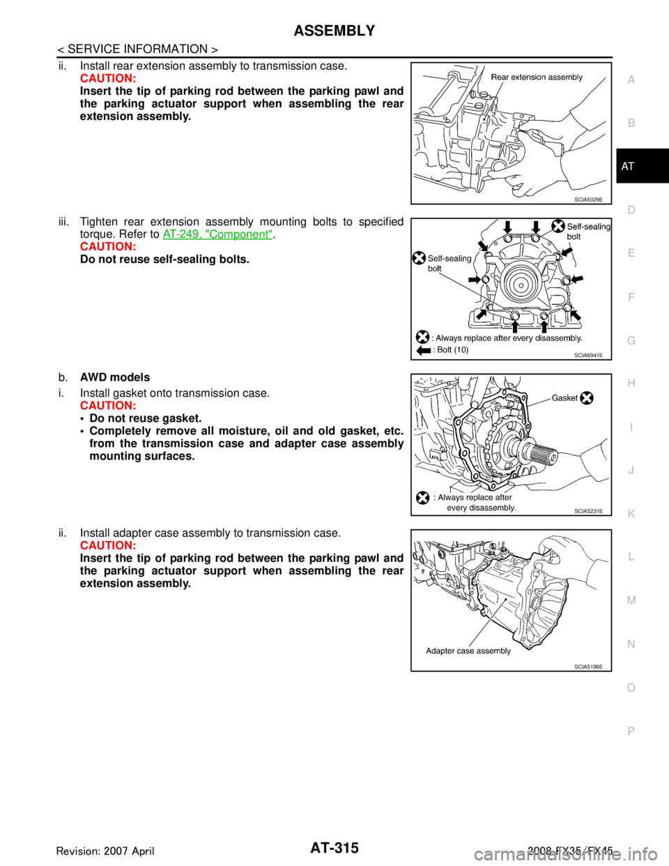
ii. Install rear extension assembly to transmission case. CAUTION:
Insert the tip of parking rod between the parking pawl and
the parking actuator suppor t when assembling the rear
extension assembly.
iii. Tighten rear extension assembly mounting bolts to specified torque. Refer to AT-249, "
Component".
CAUTION:
Do not reuse self-sealing bolts.
b. AWD m od e l s
i. Install gasket onto transmission case. CAUTION:
Do not reuse gasket.
Completely remove all moistu re, oil and old gasket, etc.
from the transmission case and adapter case assembly
mounting surfaces.
ii. Install adapter case assembly to transmission case. CAUTION:
Insert the tip of parking rod between the parking pawl and
the parking actuator suppor t when assembling the rear
extension assembly.
SCIA5029E
SCIA6941E
SCIA5231E
SCIA5186E
3AA93ABC3ACD3AC03ACA3AC03AC63AC53A913A773A893A873A873A8E3A773A983AC73AC93AC03AC3
3A893A873A873A8F3A773A9D3AAF3A8A3A8C3A863A9D3AAF3A8B3A8C
Page 389 of 3924
![INFINITI FX35 2008 Repair Manual
AT-316
< SERVICE INFORMATION >
ASSEMBLY
iii. Tighten adapter case assembly mounting bolts (1) to specifiedtorque. [With bracket (2).] Refer to AT-249, "
Component".
: Bolt (10)
CAUTION:
Do not reuse INFINITI FX35 2008 Repair Manual
AT-316
< SERVICE INFORMATION >
ASSEMBLY
iii. Tighten adapter case assembly mounting bolts (1) to specifiedtorque. [With bracket (2).] Refer to AT-249, "
Component".
: Bolt (10)
CAUTION:
Do not reuse](/img/42/57017/w960_57017-388.png)
AT-316
< SERVICE INFORMATION >
ASSEMBLY
iii. Tighten adapter case assembly mounting bolts (1) to specifiedtorque. [With bracket (2).] Refer to AT-249, "
Component".
: Bolt (10)
CAUTION:
Do not reuse self-sealing bolts (3).
Refer to GI section to mark sure icons (symbol marks) in the fig-
ure. Refer to GI-8, "
Component".
35. Install needle bearing in drum support. CAUTION:
Take care with the direction of needle bearing. Refer to
AT-264, "
Location of Adjusting Sh ims, Needle Bearings,
Thrust Washers and Snap Rings".
Apply petroleum jelly to needle bearing.
36. Install direct clutch assembly in reverse brake. CAUTION:
Make sure that drum support edge surface and direct clutch
inner boss edge surface come to almost same place.
37. Install high and low reverse clutch assembly in direct clutch.
SCIA7210E
SCIA5198E
SCIA5019E
SCIA2306E
3AA93ABC3ACD3AC03ACA3AC03AC63AC53A913A773A893A873A873A8E3A773A983AC73AC93AC03AC3
3A893A873A873A8F3A773A9D3AAF3A8A3A8C3A863A9D3AAF3A8B3A8C
Page 393 of 3924
AT-320
< SERVICE INFORMATION >
ASSEMBLY
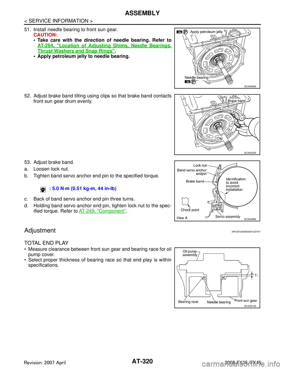
51. Install needle bearing to front sun gear.CAUTION:
Take care with the direction of needle bearing. Refer toAT-264, "
Location of Adjusting Sh ims, Needle Bearings,
Thrust Washers and Snap Rings".
Apply petroleum jelly to needle bearing.
52. Adjust brake band tilting using clips so that brake band contacts front sun gear drum evenly.
53. Adjust brake band.
a. Loosen lock nut.
b. Tighten band servo anchor end pin to the specified torque.
c. Back of band servo anchor end pin three turns.
d. Holding band servo anchor end pin, tighten lock nut to the spec- ified torque. Refer to AT-249, "
Component".
AdjustmentINFOID:0000000001327411
TOTAL END PLAY
Measure clearance between front sun gear and bearing race for oil
pump cover.
Select proper thickness of bearing race so that end play is within specifications.
SCIA2808E
SCIA5033E
: 5.0 N·m (0.51 kg-m, 44 in-lb)
SCIA5498E
SCIA2810E
3AA93ABC3ACD3AC03ACA3AC03AC63AC53A913A773A893A873A873A8E3A773A983AC73AC93AC03AC3
3A893A873A873A8F3A773A9D3AAF3A8A3A8C3A863A9D3AAF3A8B3A8C
Page 397 of 3924

AT-324
< SERVICE INFORMATION >
ASSEMBLY
5. Tighten oil pump mounting bolts to specified torque. Refer to AT-
249, "Component".
CAUTION:
Apply ATF to oil pump bushing.
6. Install O-ring to input clutch assembly. CAUTION:
Do not reuse O-ring.
Apply ATF to O-ring.
7. Install converter housing to transmission case, and then tighten converter housing mounting bolts (1) to the specified torque.
Refer to AT-249, "
Component".
: Bolt (8)
CAUTION:
Do not reuse self-sealing bolt (2).
8. Make sure that brake band does not close turbine revolution sensor hole.
9. Install control valve with TCM.
a. Connect TCM connector and park/neutral position switch con- nector.
SCIA2300E
SCIA5011E
SCIA7985E
SCIA5034E
SCIA5449E
3AA93ABC3ACD3AC03ACA3AC03AC63AC53A913A773A893A873A873A8E3A773A983AC73AC93AC03AC3
3A893A873A873A8F3A773A9D3AAF3A8A3A8C3A863A9D3AAF3A8B3A8C
Page 398 of 3924
ASSEMBLYAT-325
< SERVICE INFORMATION >
DE
F
G H
I
J
K L
M A
B
AT
N
O P
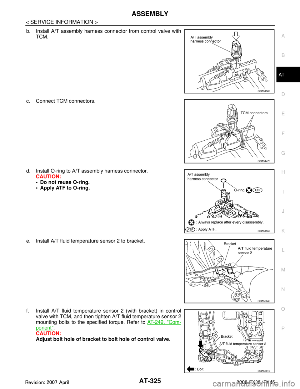
b. Install A/T assembly harness connector from control valve with TCM.
c. Connect TCM connectors.
d. Install O-ring to A/T assembly harness connector. CAUTION:
Do not reuse O-ring.
Apply ATF to O-ring.
e. Install A/T fluid temperature sensor 2 to bracket.
f. Install A/T fluid temperature sens or 2 (with bracket) in control
valve with TCM, and then tighten A/T fluid temperature sensor 2
mounting bolts to the specified torque. Refer to AT-249, "
Com-
ponent".
CAUTION:
Adjust bolt hole of bracket to bolt hole of control valve.
SCIA5450E
SCIA5447E
SCIA5155E
SCIA5264E
SCIA5301E
3AA93ABC3ACD3AC03ACA3AC03AC63AC53A913A773A893A873A873A8E3A773A983AC73AC93AC03AC3
3A893A873A873A8F3A773A9D3AAF3A8A3A8C3A863A9D3AAF3A8B3A8C
Page 399 of 3924

AT-326
< SERVICE INFORMATION >
ASSEMBLY
g. Install control valve with TCM in transmission case.CAUTION:
Make sure that turbine revolu tion sensor securely installs
turbine revolution sensor hole.
Hang down revolution senso r harness toward outside so
as not to disturb installation of control valve with TCM.
Adjust A/T assembly harness co nnector of control valve
with TCM to terminal hole of transmission case.
Assemble it so that manual valve cutout is engaged with manual plate projection.
h. Install bolts A, B and C to control valve with TCM. : Front
i. Tighten bolt 1, 2 and 3 temporarily to prevent dislocation. After that tighten them in order (1 → 2 → 3), and then tighten other
bolts to the specified torque. Refer to AT-249, "
Component".
: Front
SCIA5034E
SCIA5035E
Bolt symbol Length mm (in) Number of bolts
A 42 (1.65) 5
B 55 (2.17) 6
C 40 (1.57) 1
SCIA8077E
SCIA8078E
3AA93ABC3ACD3AC03ACA3AC03AC63AC53A913A773A893A873A873A8E3A773A983AC73AC93AC03AC3
3A893A873A873A8F3A773A9D3AAF3A8A3A8C3A863A9D3AAF3A8B3A8C
Page 401 of 3924
AT-328
< SERVICE INFORMATION >
ASSEMBLY
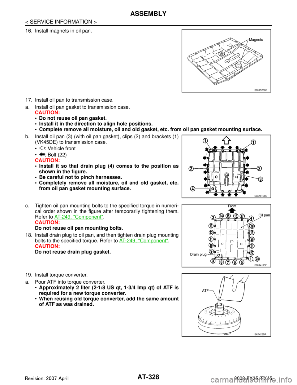
16. Install magnets in oil pan.
17. Install oil pan to transmission case.
a. Install oil pan gasket to transmission case.CAUTION:
Do not reuse oil pan gasket.
Install it in the direction to align hole positions.
Complete remove all moisture, oil and old gasket, etc. from oil pan gasket mounting surface.
b. Install oil pan (3) (with oil pan gasket), clips (2) and brackets (1) (VK45DE) to transmission case.
: Vehicle front
: Bolt (22)
CAUTION:
Install it so that drain plug (4) comes to the position as
shown in the figure.
Be careful not to pinch harnesses.
Completely remove all moisture, oil and old gasket, etc. from oil pan gasket mounting surface.
c. Tighten oil pan mounting bolts to the specified torque in numeri- cal order shown in the figure after temporarily tightening them.
Refer to AT-249, "
Component".
CAUTION:
Do not reuse oil pan mounting bolts.
18. Install drain plug to oil pan, and then tighten drain plug mounting bolts to the specified torque. Refer to AT-249, "
Component".
CAUTION:
Do not reuse drain plug gasket.
19. Install torque converter.
a. Pour ATF into torque converter. Approximately 2 liter (2-1/8 US qt, 1-3/4 Imp qt) of ATF is
required for a new torque converter.
When reusing old torque converter, add the same amount
of ATF as was drained.
SCIA5200E
SCIA8128E
SCIA4113E
SAT428DA
3AA93ABC3ACD3AC03ACA3AC03AC63AC53A913A773A893A873A873A8E3A773A983AC73AC93AC03AC3
3A893A873A873A8F3A773A9D3AAF3A8A3A8C3A863A9D3AAF3A8B3A8C