parking sensors INFINITI FX35 2008 Service Manual
[x] Cancel search | Manufacturer: INFINITI, Model Year: 2008, Model line: FX35, Model: INFINITI FX35 2008Pages: 3924, PDF Size: 81.37 MB
Page 102 of 3924

A/T CONTROL SYSTEMAT-29
< SERVICE INFORMATION >
DE
F
G H
I
J
K L
M A
B
AT
N
O P
TCM FunctionINFOID:0000000001327135
The function of the TCM is to:
Receive input signals sent from various switches and sensors.
Determine required line pressure, shifting point, lock-up operation, and engine brake operation.
Send required output signals to the respective solenoids.
CONTROL SYSTEM OUTLINE
The automatic transmission senses vehicle operating condi tions through various sensors or signals. It always
controls the optimum shift position and reduces shifting and lock-up shocks.
1. Front brake 2. Input clutch 3. Direct clutch
4. High and low reverse clutch 5. Reverse brake 6. Forward brake
7. Low coast brake 8. 1st one-way clutch 9. Forward one-way clutch
10. 3rd one-way clutch 11. Front sun gear 12. Input shaft
13. Mid internal gear 14. Front internal gear 15. Rear carrier
16. Rear sun gear 17. Mid sun gear 18. Front carrier
19. Mid carrier 20. Rear internal gear 21. Output shaft
22. Parking gear 23. Parking pawl
SCIA1519E
SENSORS (or SIGNALS)
⇒TCM
⇒ACTUATORS
PNP switch
Accelerator pedal position signal
Closed throttle position signal
Wide open throttle position signal
Engine speed signal
A/T fluid temperature sensor
Revolution sensor
Vehicle speed signal
Manual mode switch signal
Stop lamp switch signal
Turbine revolution sensor
ATF pressure switch Shift control
Line pressure control
Lock-up control
Engine brake control
Timing control
Fail-safe control
Self-diagnosis
CONSULT-III co
mmunication
line
Duet-EA control
CAN system Input clutch solenoid valve
Direct clutch solenoid valve
Front brake solenoid valve
High and low reverse clutch sole-
noid valve
Low coast brake solenoid valve
Torque converter clutch solenoid
valve
Line pressure solenoid valve
A/T CHECK indicator lamp
Starter relay
Back-up lamp relay
:
Page 3799 of 3924

AWD SYSTEMTF-13
< SERVICE INFORMATION >
CEF
G H
I
J
K L
M A
B
TF
N
O P
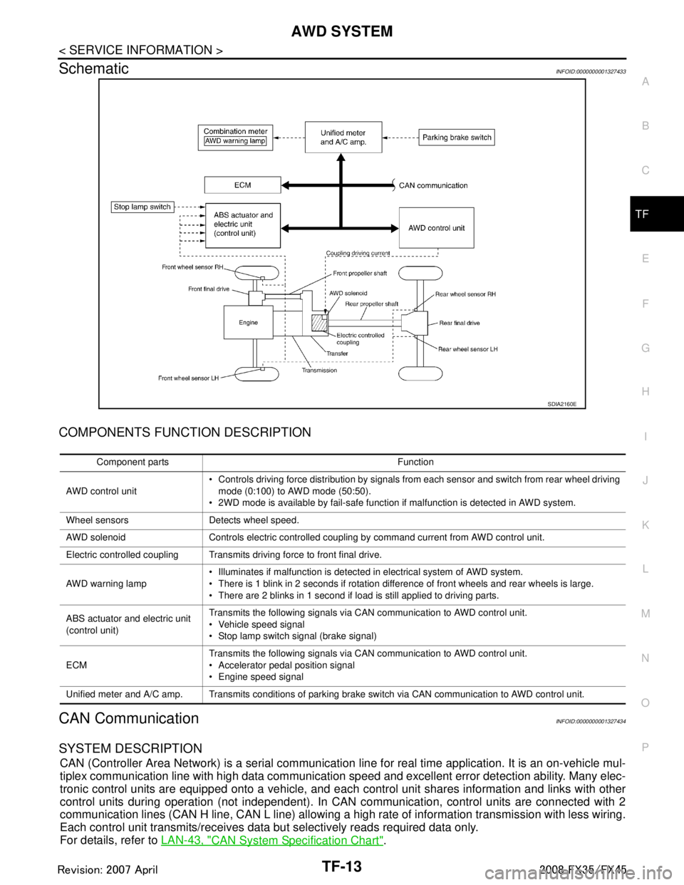
SchematicINFOID:0000000001327433
COMPONENTS FUNCTION DESCRIPTION
CAN CommunicationINFOID:0000000001327434
SYSTEM DESCRIPTION
CAN (Controller Area Network) is a serial communication li ne for real time application. It is an on-vehicle mul-
tiplex communication line with high data communication speed and excellent error detection ability. Many elec-
tronic control units are equipped onto a vehicle, and each control unit shares information and links with other
control units during operation (not independent). In CAN communication, control units are connected with 2
communication lines (CAN H line, CAN L line) allowing a high rate of information transmission with less wiring.
Each control unit transmits/receives data but selectively reads required data only.
For details, refer to LAN-43, "
CAN System Specification Chart".
SDIA2160E
Component parts Function
AWD control unit Controls driving force distribution by signals from each sensor and switch from rear wheel driving
mode (0:100) to AWD mode (50:50).
2WD mode is available by fail-safe function if malfunction is detected in AWD system.
Wheel sensors Detects wheel speed.
AWD solenoid Controls electric controlled coupling by command current from AWD control unit.
Electric controlled coupling Transmits driving force to front final drive.
AWD warning lamp Illuminates if malfunction is detected in electrical system of AWD system.
There is 1 blink in 2 seconds if rotation difference of front wheels and rear wheels is large.
There are 2 blinks in 1 second if load is still applied to driving parts.
ABS actuator and electric unit
(control unit) Transmits the following signals via CAN communication to AWD control unit.
Vehicle speed signal
Stop lamp switch signal (brake signal)
ECM Transmits the following signals via CAN communication to AWD control unit.
Accelerator pedal position signal
Engine speed signal
Unified meter and A/C amp. Transmits conditions of parking brake switch via CAN communication to AWD control unit.
3AA93ABC3ACD3AC03ACA3AC03AC63AC53A913A773A893A873A873A8E3A773A983AC73AC93AC03AC3
3A893A873A873A8F3A773A9D3AAF3A8A3A8C3A863A9D3AAF3A8B3A8C