INFINITI G35 2006 Owners Manual
Manufacturer: INFINITI, Model Year: 2006, Model line: G35, Model: INFINITI G35 2006Pages: 344, PDF Size: 6.81 MB
Page 151 of 344
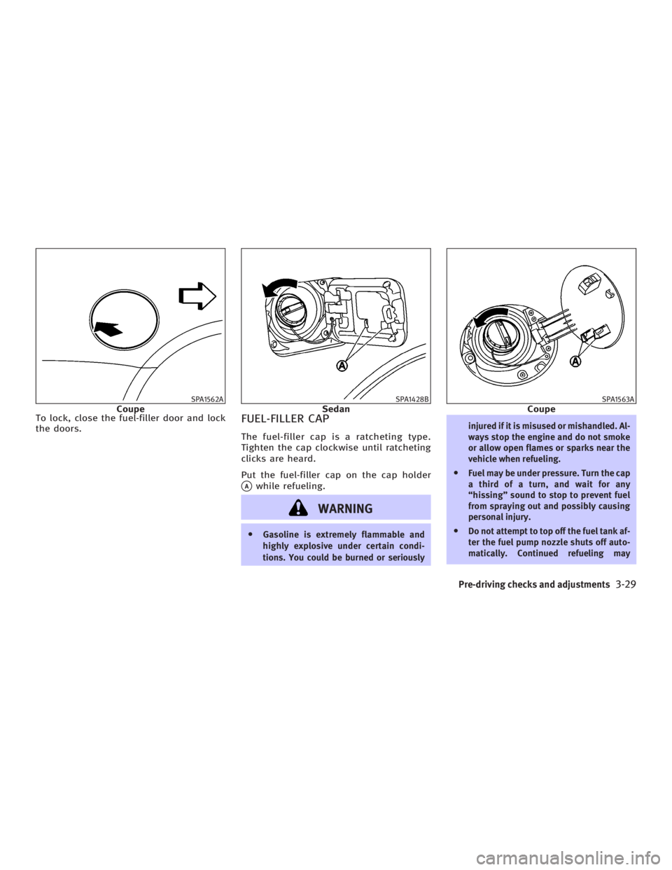
To lock, close the fuel-filler door and lock
the doors.
FUEL-FILLER CAP The fuel-filler cap is a ratcheting type.
Tighten the cap clockwise until ratcheting
clicks are heard.
Put the fuel-filler cap on the cap holder
q A
while refueling.
WARNING O Gasoline is extremely flammable and
highly explosive under certain condi-
tions. You could be burned or seriously injured if it is misused or mishandled. Al-
ways stop the engine and do not smoke
or allow open flames or sparks near the
vehicle when refueling.
O Fuel may be under pressure. Turn the cap
a third of a turn, and wait for any
ªhissingº sound to stop to prevent fuel
from spraying out and possibly causing
personal injury.
O Do not attempt to top off the fuel tank af-
ter the fuel pump nozzle shuts off auto-
matically. Continued refueling maySPA1562A
Coupe SPA1428B
Sedan SPA1563A
Coupe
Pre-driving checks and adjustments
3-29
w 06.1.4/V35-D/V5.0
X
Page 152 of 344
cause fuel overflow, resulting in fuel-
spray and possibly a fire.
O Use only an original equipment type
fuel-filler cap as a replacement. It has a
built-in safety valve needed for proper
operation of the fuel system and emis-
sion control system. An incorrect cap can
result in a serious malfunction and pos-
sible injury. An incorrect cap could also
cause the
malfunction indicator
lamp to illuminate.
O Do not fill a portable fuel container in the
vehicle or trailer. Static electricity can
cause an explosion of flammable liquid,
vapor or gas in any vehicle or trailer. To
reduce the risk of serious injury or death
when filling portable fuel containers:
Ð Always place the container on the
ground when filling.
Ð Do not use electronic devices when
filling.
Ð Keep the pump nozzle in contact with
the container while you are filling it.
Ð Use only approved portable fuel con-
tainers for flammable liquid.
O Never pour fuel into the throttle body to
attempt to start your vehicle. CAUTION O If fuel is spilled on the vehicle body,
flush it away with water to avoid paint
damage.
O Tighten until the fuel-filler cap clicks.
Failure to tighten the fuel-filler cap prop-
erly may cause the
malfunction in-
dicator lamp (MIL) to illuminate. If the
lamp illuminates because the fuel-
filler cap is loose or missing, tighten or
install the cap and continue to drive the
vehicle. The
lamp should turn off
after a few driving trips. If the
lamp
does not turn off after a few driving trips,
have the vehicle inspected by an INFINITI
dealer.
O For additional information, see the ªMal-
function indicator lamp (MIL)º in the ª2.
Instruments and controlsº section.
MANUAL OPERATION
WARNING Do not adjust the steering wheel while
driving. You could lose control of your ve-
hicle and cause an accident.
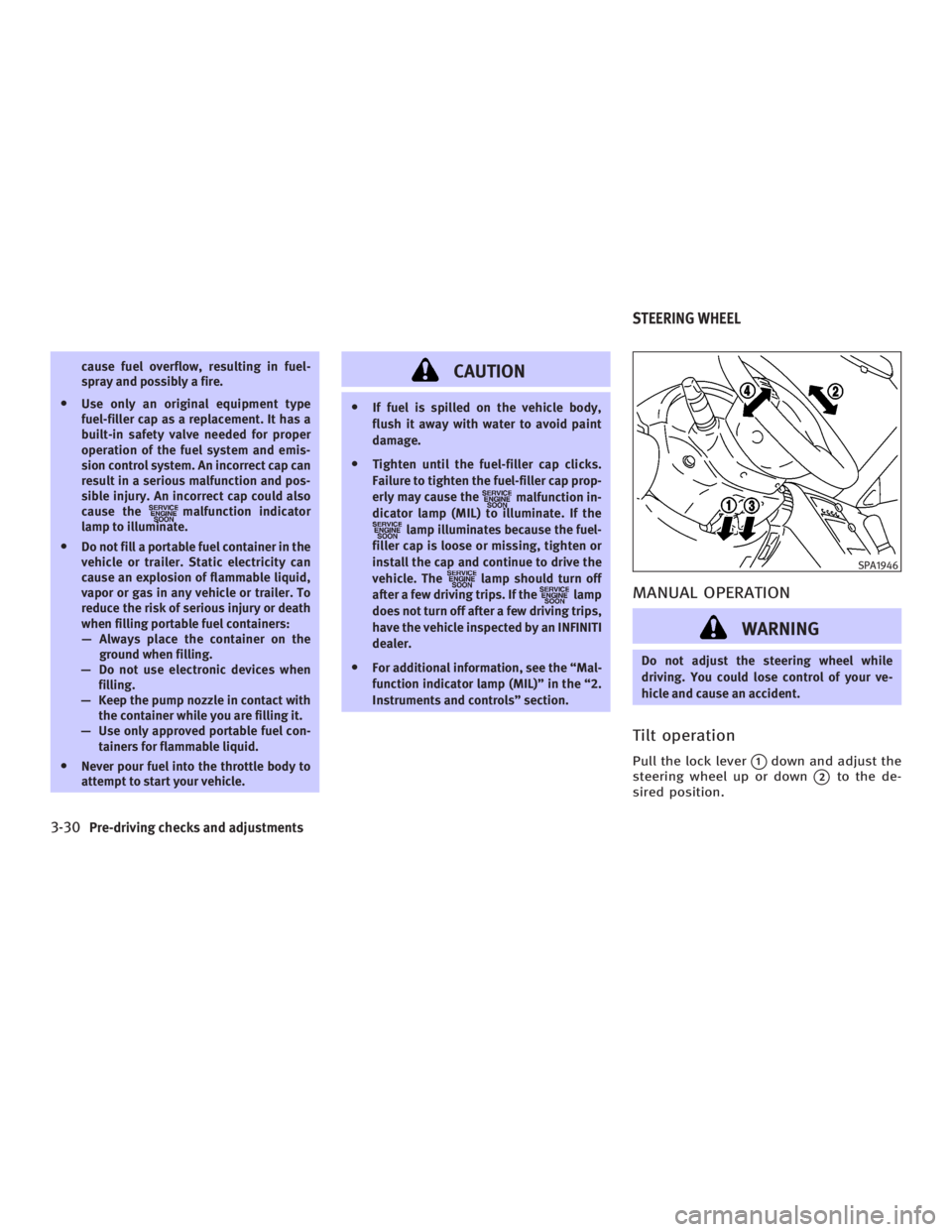
Tilt operation Pull the lock lever
q 1
down and adjust the
steering wheel up or down
q 2
to the de-
sired position. SPA1946
STEERING WHEEL
3-30 Pre-driving checks and adjustments
w 06.1.4/V35-D/V5.0
X
Page 153 of 344
Push the lock lever up securely to lock
the steering wheel in place.
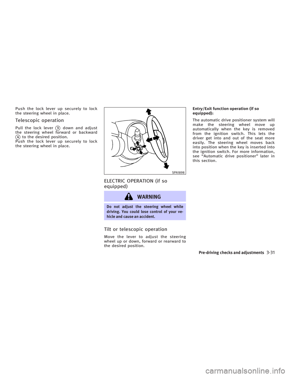
Telescopic operation Pull the lock lever
q 3
down and adjust
the steering wheel forward or backward
q 4
to the desired position.
Push the lock lever up securely to lock
the steering wheel in place.
ELECTRIC OPERATION (if so
equipped)
WARNING Do not adjust the steering wheel while
driving. You could lose control of your ve-
hicle and cause an accident.
Tilt or telescopic operation Move the lever to adjust the steering
wheel up or down, forward or rearward to
the desired position. Entry/Exit function operation (if so
equipped):
The automatic drive positioner system will
make the steering wheel move up
automatically when the key is removed
from the ignition switch. This lets the
driver get into and out of the seat more
easily. The steering wheel moves back
into position when the key is inserted into
the ignition switch. For more information,
see ªAutomatic drive positionerº later in
this section. SPA1898
Pre-driving checks and adjustments
3-31
w 06.1.4/V35-D/V5.0
X
Page 154 of 344
CAUTION O Do not store the main sun visor before
storing the extension sun visor.
O Do not pull the extension sun visor forc-
edly downward.
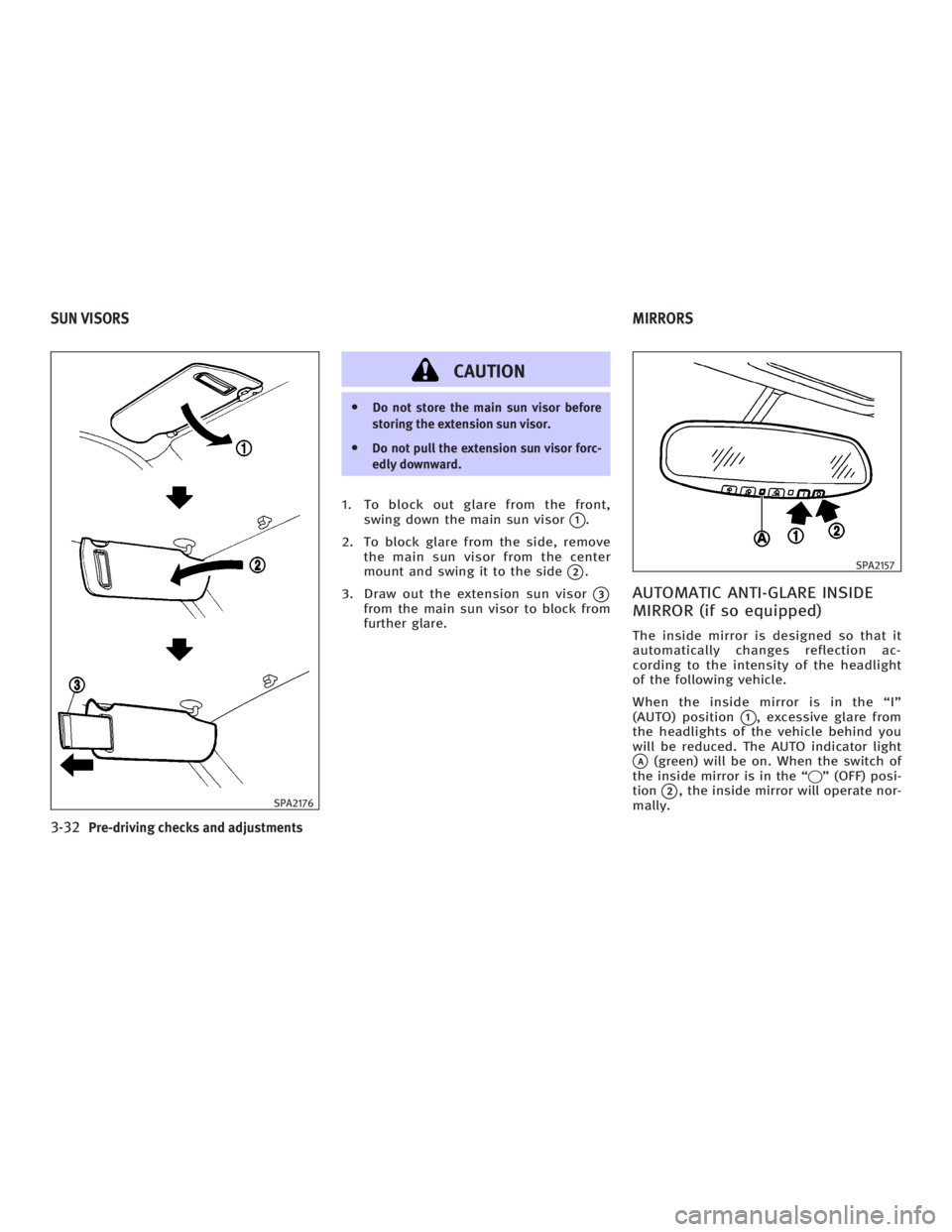
1. To block out glare from the front,
swing down the main sun visor
q 1
.
2. To block glare from the side, remove
the main sun visor from the center
mount and swing it to the side
q 2
.
3. Draw out the extension sun visor
q 3
from the main sun visor to block from
further glare.
AUTOMATIC ANTI-GLARE INSIDE
MIRROR (if so equipped) The inside mirror is designed so that it
automatically changes reflection ac-
cording to the intensity of the headlight
of the following vehicle.
When the inside mirror is in the ªIº
(AUTO) position
q 1
, excessive glare from
the headlights of the vehicle behind you
will be reduced. The AUTO indicator light
q A
(green) will be on. When the switch of
the inside mirror is in the ª q º (OFF) posi-
tion
q 2
, the inside mirror will operate nor-
mally.SPA2176 SPA2157
SUN VISORS MIRRORS
3-32 Pre-driving checks and adjustments
w 06.1.4/V35-D/V5.0
X
Page 155 of 344
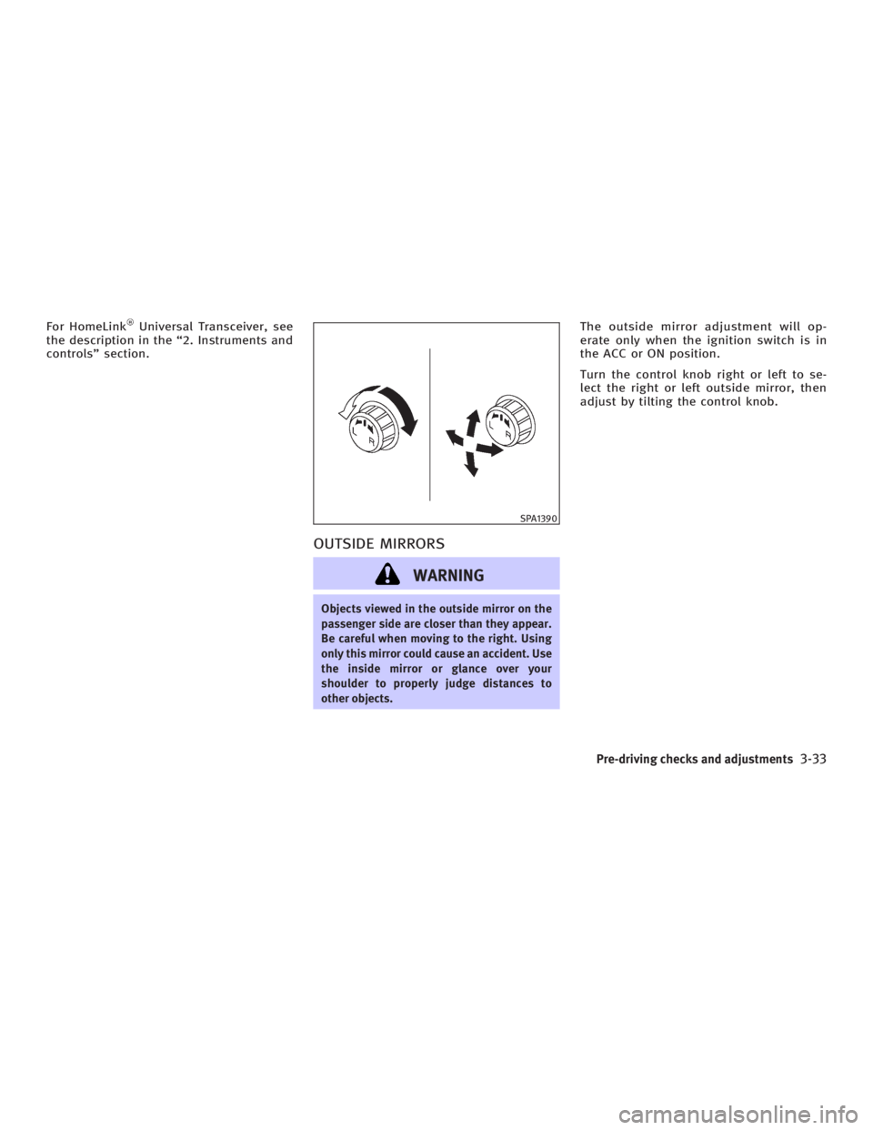
For HomeLink Universal Transceiver, see
the description in the ª2. Instruments and
controlsº section.
OUTSIDE MIRRORS
WARNING Objects viewed in the outside mirror on the
passenger side are closer than they appear.
Be careful when moving to the right. Using
only this mirror could cause an accident. Use
the inside mirror or glance over your
shoulder to properly judge distances to
other objects. The outside mirror adjustment will op-
erate only when the ignition switch is in
the ACC or ON position.
Turn the control knob right or left to se-
lect the right or left outside mirror, then
adjust by tilting the control knob. SPA1390
Pre-driving checks and adjustments
3-33
w 06.1.4/V35-D/V5.0
X
Page 156 of 344
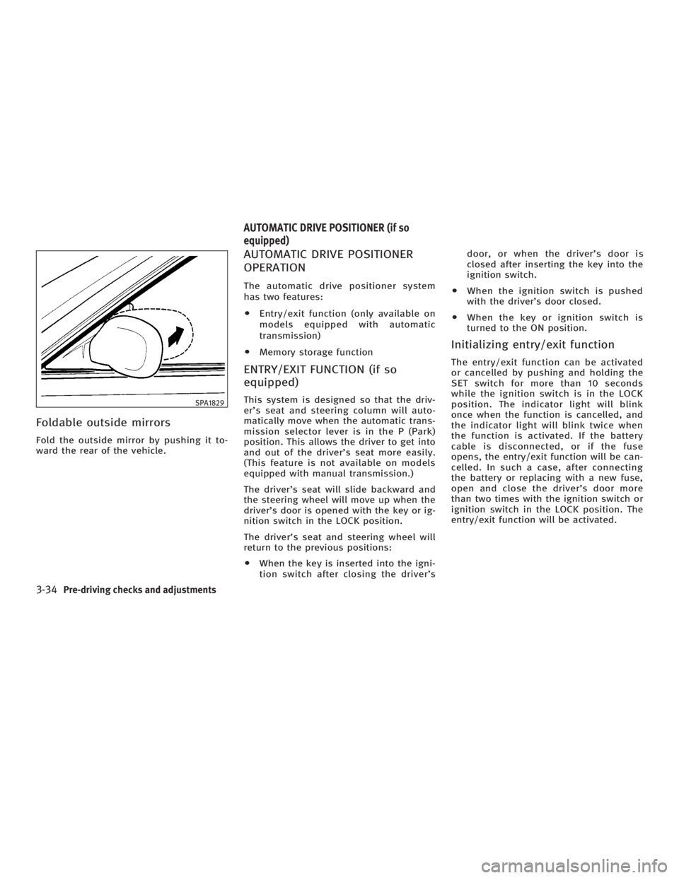
Foldable outside mirrors Fold the outside mirror by pushing it to-
ward the rear of the vehicle. AUTOMATIC DRIVE POSITIONER
OPERATION The automatic drive positioner system
has two features:
O Entry/exit function (only available on
models equipped with automatic
transmission)
O Memory storage function
ENTRY/EXIT FUNCTION (if so
equipped) This system is designed so that the driv-
er's seat and steering column will auto-
matically move when the automatic trans-
mission selector lever is in the P (Park)
position. This allows the driver to get into
and out of the driver's seat more easily.
(This feature is not available on models
equipped with manual transmission.)
The driver's seat will slide backward and
the steering wheel will move up when the
driver's door is opened with the key or ig-
nition switch in the LOCK position.
The driver's seat and steering wheel will
return to the previous positions:
O When the key is inserted into the igni-
tion switch after closing the driver's door, or when the driver's door is
closed after inserting the key into the
ignition switch.
O When the ignition switch is pushed
with the driver's door closed.
O When the key or ignition switch is
turned to the ON position.
Initializing entry/exit function The entry/exit function can be activated
or cancelled by pushing and holding the
SET switch for more than 10 seconds
while the ignition switch is in the LOCK
position. The indicator light will blink
once when the function is cancelled, and
the indicator light will blink twice when
the function is activated. If the battery
cable is disconnected, or if the fuse
opens, the entry/exit function will be can-
celled. In such a case, after connecting
the battery or replacing with a new fuse,
open and close the driver's door more
than two times with the ignition switch or
ignition switch in the LOCK position. The
entry/exit function will be activated.SPA1829
AUTOMATIC DRIVE POSITIONER (if so
equipped)
3-34 Pre-driving checks and adjustments
w 06.1.4/V35-D/V5.0
X
Page 157 of 344
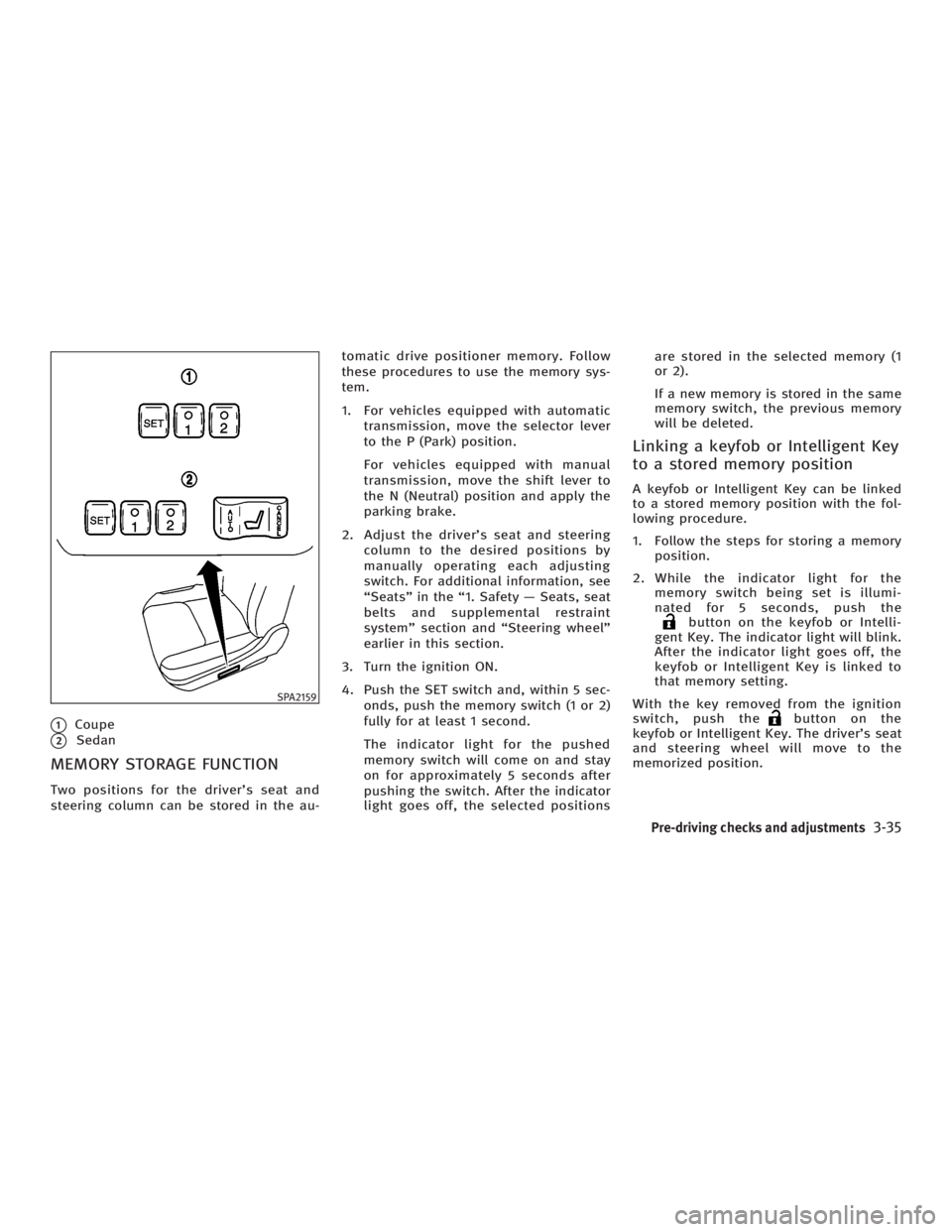
q 1
Coupe
q 2
Sedan
MEMORY STORAGE FUNCTION Two positions for the driver's seat and
steering column can be stored in the au- tomatic drive positioner memory. Follow
these procedures to use the memory sys-
tem.
1. For vehicles equipped with automatic
transmission, move the selector lever
to the P (Park) position.
For vehicles equipped with manual
transmission, move the shift lever to
the N (Neutral) position and apply the
parking brake.
2. Adjust the driver's seat and steering
column to the desired positions by
manually operating each adjusting
switch. For additional information, see
ªSeatsº in the ª1. Safety Ð Seats, seat
belts and supplemental restraint
systemº section and ªSteering wheelº
earlier in this section.
3. Turn the ignition ON.
4. Push the SET switch and, within 5 sec-
onds, push the memory switch (1 or 2)
fully for at least 1 second.
The indicator light for the pushed
memory switch will come on and stay
on for approximately 5 seconds after
pushing the switch. After the indicator
light goes off, the selected positions are stored in the selected memory (1
or 2).
If a new memory is stored in the same
memory switch, the previous memory
will be deleted.
Linking a keyfob or Intelligent Key
to a stored memory position A keyfob or Intelligent Key can be linked
to a stored memory position with the fol-
lowing procedure.
1. Follow the steps for storing a memory
position.
2. While the indicator light for the
memory switch being set is illumi-
nated for 5 seconds, push the
button on the keyfob or Intelli-
gent Key. The indicator light will blink.
After the indicator light goes off, the
keyfob or Intelligent Key is linked to
that memory setting.
With the key removed from the ignition
switch, push the button on the
keyfob or Intelligent Key. The driver's seat
and steering wheel will move to the
memorized position.SPA2159
Pre-driving checks and adjustments
3-35
w 06.1.4/V35-D/V5.0
X
Page 158 of 344
Confirming memory storage O Turn the ignition ON and push the SET
switch. If the main memory has not
been stored, the indicator light will
come on for approximately 0.5 sec-
onds. When the memory has stored in
position, the indicator light will stay
on for approximately 5 seconds.
O If the battery cable is disconnected, or
if the fuse opens, the memory will be
canceled.
Reset the desired position using the
previous procedure.
Selecting the memorized position 1. For vehicles equipped with automatic
transmission, move the selector lever
to the P (Park) position.
For vehicles equipped with manual
transmission, move the shift lever in
the N (Neutral) position and apply the
parking brake.
2. Use one of the following methods to
move the driver's seat and the
steering wheel.
O Turn the ignition switch to the ªONº
position and push the memory switch (1 or 2) fully for at least 1
second.
O Within 45 seconds of opening the
driver's door, push the memory
switch (1 or 2) fully for at least 1
second.
The driver's seat and steering column
will move to the memorized position
with the indicator light flashing, and
then the light will stay on for approxi-
mately 5 seconds.
SYSTEM OPERATION The automatic drive positioner system will
not work or will stop operating under the
following conditions:
O when the vehicle speed is above 4
MPH (7 km/h).
O when the adjusting switch for the driv-
er's seat and steering column is
turned on while the automatic drive
positioner is operating.
O when the cancel switch (if so
equipped) is pushed to the CANCEL
side. (However, it will not be cancelled
if the switch is pushed while the seat
and steering column are returning to the previous positions (entry/exit
function).)
O when the memory switch 1 or 2 is not
pushed and held for at least 1 second.
O when the seat has already been
moved to the memorized position.
O when no seat position is stored in the
memory switch.
O when the parking brake is not applied.
Ð MT models
O when the speed is above 4 MPH (7
km/h) while the parking brake is ap-
plied. Ð MT models
To restart the drive positioner system,
move the parking brake to off and on.
O when the front seat is folded for oper-
ating the walk-in mechanism (if so
equipped).
O when the engine is started while the
automatic drive positioner is operating.
O when the AT selector lever is moved
from the P position to any other posi-
tion. (However, it will not be cancelled
if the switch is pushed while the seat
and steering column are returning to
the previous positions (entry/exit
function).)
3-36 Pre-driving checks and adjustments
w 06.1.4/V35-D/V5.0
X
Page 159 of 344

O when the driver's door remains open
for more than 45 seconds and the igni-
tion switch is not in the ON position.
CANCEL SWITCH (if so equipped) When the CANCEL side of the switch is
pushed, the automatic drive positioner
system will not function.
When the AUTO side of the switch is
pushed, the system will function.
Pre-driving checks and adjustments
3-37
w 06.1.5/V35-D/V5.0
X
Page 160 of 344

MEMO
3-38 Pre-driving checks and adjustments
w 06.1.5/V35-D/V5.0
X