capacity INFINITI M35 2006 Factory Service Manual
[x] Cancel search | Manufacturer: INFINITI, Model Year: 2006, Model line: M35, Model: INFINITI M35 2006Pages: 5621, PDF Size: 65.56 MB
Page 91 of 5621
AT-12
A/T FLUID
Revision: 2006 January2006 M35/M45
A/T FLUIDPFP:KLE40
Changing A/T FluidNCS001JI
1. Warm up ATF.
2. Stop engine.
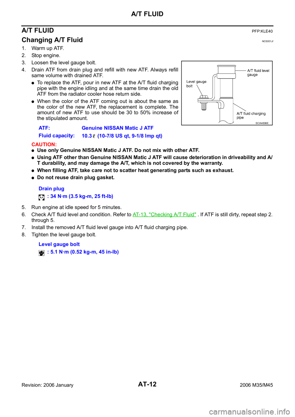
3. Loosen the level gauge bolt.
4. Drain ATF from drain plug and refill with new ATF. Always refill
same volume with drained ATF.
To replace the ATF, pour in new ATF at the A/T fluid charging
pipe with the engine idling and at the same time drain the old
ATF from the radiator cooler hose return side.
When the color of the ATF coming out is about the same as
the color of the new ATF, the replacement is complete. The
amount of new ATF to use should be 30 to 50% increase of
the stipulated amount.
CAUTION:
Use only Genuine NISSAN Matic J ATF. Do not mix with other ATF.
Using ATF other than Genuine NISSAN Matic J ATF will cause deterioration in driveability and A/
T durability, and may damage the A/T, which is not covered by the warranty.
When filling ATF, take care not to scatter heat generating parts such as exhaust.
Do not reuse drain plug gasket.
5. Run engine at idle speed for 5 minutes.
6. Check A/T fluid level and condition. Refer to AT- 1 3 , "
Checking A/T Fluid" . If ATF is still dirty, repeat step 2.
through 5.
7. Install the removed A/T fluid level gauge into A/T fluid charging pipe.
8. Tighten the level gauge bolt.ATF: Genuine NISSAN Matic J ATF
Fluid capacity:
10.3 (10-7/8 US qt, 9-1/8 lmp qt)
Drain plug
: 34 Nꞏm (3.5 kg-m, 25 ft-lb)
Level gauge bolt
: 5.1 Nꞏm (0.52 kg-m, 45 in-lb)
SCIA4896E
Page 117 of 5621
AT-38
A/T CONTROL SYSTEM
Revision: 2006 January2006 M35/M45
Engine Brake ControlNCS001JV
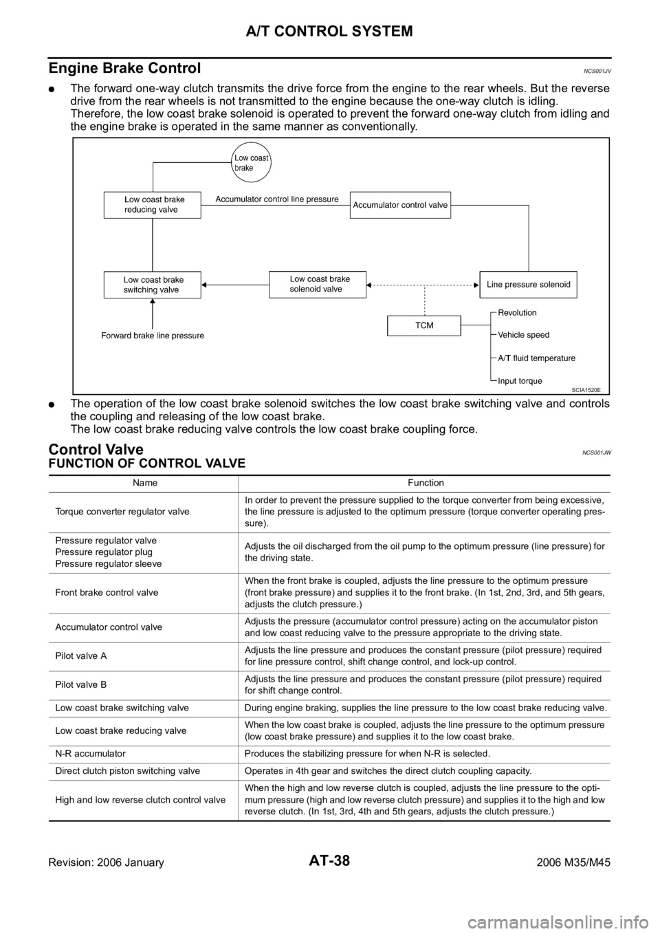
The forward one-way clutch transmits the drive force from the engine to the rear wheels. But the reverse
drive from the rear wheels is not transmitted to the engine because the one-way clutch is idling.
Therefore, the low coast brake solenoid is operated to prevent the forward one-way clutch from idling and
the engine brake is operated in the same manner as conventionally.
The operation of the low coast brake solenoid switches the low coast brake switching valve and controls
the coupling and releasing of the low coast brake.
The low coast brake reducing valve controls the low coast brake coupling force.
Control ValveNCS001JW
FUNCTION OF CONTROL VALVE
SCIA1520E
Name Function
Torque converter regulator valveIn order to prevent the pressure supplied to the torque converter from being excessive,
the line pressure is adjusted to the optimum pressure (torque converter operating pres-
sure).
Pressure regulator valve
Pressure regulator plug
Pressure regulator sleeveAdjusts the oil discharged from the oil pump to the optimum pressure (line pressure) for
the driving state.
Front brake control valveWhen the front brake is coupled, adjusts the line pressure to the optimum pressure
(front brake pressure) and supplies it to the front brake. (In 1st, 2nd, 3rd, and 5th gears,
adjusts the clutch pressure.)
Accumulator control valveAdjusts the pressure (accumulator control pressure) acting on the accumulator piston
and low coast reducing valve to the pressure appropriate to the driving state.
Pilot valve AAdjusts the line pressure and produces the constant pressure (pilot pressure) required
for line pressure control, shift change control, and lock-up control.
Pilot valve BAdjusts the line pressure and produces the constant pressure (pilot pressure) required
for shift change control.
Low coast brake switching valve During engine braking, supplies the line pressure to the low coast brake reducing valve.
Low coast brake reducing valveWhen the low coast brake is coupled, adjusts the line pressure to the optimum pressure
(low coast brake pressure) and supplies it to the low coast brake.
N-R accumulator Produces the stabilizing pressure for when N-R is selected.
Direct clutch piston switching valve Operates in 4th gear and switches the direct clutch coupling capacity.
High and low reverse clutch control valveWhen the high and low reverse clutch is coupled, adjusts the line pressure to the opti-
mum pressure (high and low reverse clutch pressure) and supplies it to the high and low
reverse clutch. (In 1st, 3rd, 4th and 5th gears, adjusts the clutch pressure.)
Page 444 of 5621

SERVICE DATA AND SPECIFICATIONS (SDS)
AT-365
D
E
F
G
H
I
J
K
L
MA
B
AT
Revision: 2006 January2006 M35/M45
SERVICE DATA AND SPECIFICATIONS (SDS)PFP:00030
General SpecificationsNCS001RD
*1: Refer to MA-12, "Fluids and Lubricants" .
Vehicle Speed at Which Gear Shifting OccursNCS001RE
2WD MODELS
At half throttle, the accelerator opening is 4/8 of the full opening.
At half throttle, the accelerator opening is 4/8 of the full opening.
AWD MODELS
At half throttle, the accelerator opening is 4/8 of the full opening. Applied modelVQ35DE engine VK45DE engine
2WD AWD 2WD
Automatic transmission model RE5R05A
Transmission model code number 97X06, 98X1A 97X07, 98X0E 95X12, 95X7A
Stall torque ratio 1.72: 1 1.85: 1
Transmission gear ratio1st 3.842 3.827
2nd 2.353 2.368
3rd 1.529 1.520
4th 1.000 1.000
5th 0.839 0.834
Reverse 2.765 2.613
Recommended fluid Genuine NISSAN Matic J ATF*1
Fluid capacity 10.3 liter (10-7/8 US qt, 9-1/8 Imp qt)
CAUTION:
Use only Genuine NISSAN Matic J ATF. Do not mix with other fluid.
Using ATF other than Genuine NISSAN Matic J ATF will deteriorate in driveability and A/T durability, and may damage the
A/T, which is not covered by the warranty.
Engine model VQ35DE
Throttle positionVehicle speed km/h (MPH)
D
1 D2D2 D3D3 D4D4 D5D5 D4D4 D3D3 D2D2 D1
Full throttle 50 - 58
(31 - 36)85 - 93
(53 - 58)127 - 135
(79 - 84)196 - 204
(122 - 127)192 - 200
(119 - 124)114- 122
(71 - 76)70 - 78
(43 - 48)26 - 34
(16 - 21)
Half throttle 40 - 48
(25 - 30)69 - 77
(43 - 48)107 - 115
(66 - 71)139 - 147
(86 - 91)111 - 11 9
(69 - 74)67 - 75
(42 - 47)34 - 42
(21 - 26)19 - 27
(12 - 17)
Engine model VK45DE
Throttle positionVehicle speed km/h (MPH)
D
1 D2D2 D3D3 D4D4 D5D5 D4D4 D3D3 D2D2 D1
Full throttle 54 - 62
(34 - 39)89 - 97
(55 - 60)139 - 147
(86 - 91)207 - 215
(129 - 134)203 - 211
(126 - 131)122 - 130
(76 - 81)73 - 81
(45 - 50)28 - 36
(17 - 22)
Half throttle 46 - 54
(29 - 34)81 - 89
(50 - 55)126 - 134
(78 - 83)155 - 163
(96 - 101)128 - 136
(80 - 85)70 - 78
(43 - 48)28 - 36
(17 - 22)7 - 15
(4 - 9)
Engine model VQ35DE
Throttle positionVehicle speed km/h (MPH)
D
1 D2D2 D3D3 D4D4 D5D5 D4D4 D3D3 D2D2 D1
Full throttle 48 - 56
(30 - 35)81 - 89
(50 - 55)121 - 129
(75 - 80)188 - 196
(117 - 122)184 - 192
(114 - 119)109 - 117
(68 - 73)66 - 74
(41 - 46)25 - 33
(16 - 21)
Half throttle 38 - 46
(24 - 29)66 - 74
(41 - 46)102 - 110
(63 - 68)133 - 141
(83 - 88)106 - 114
(66 - 71)64 - 72
(40 - 45)32 - 40
(20 - 25)18 - 26
(11 - 16)
Page 464 of 5621

PREPARATION
ATC-17
C
D
E
F
G
H
I
K
L
MA
B
AT C
Revision: 2006 January2006 M35/M45
HFC-134a (R-134a) Service Tools and EquipmentNJS000FX
Never mix HFC-134a (R-134a) refrigerant and/or its specified lubricant with CFC-12 (R-12) refrigerant and/or
its lubricant.
Separate and non-interchangeable service equipment must be used for handling each type of refrigerant/lubri-
cant.
Refrigerant container fittings, service hose fittings and service equipment fittings (equipment which handles
refrigerant and/or lubricant) are different between CFC-12 (R-12) and HFC-134a (R-134a). This is to avoid
mixed use of the refrigerants/lubricant.
Never use adapters that convert one size fitting to another: refrigerant/lubricant contamination occurs and
compressor malfunction may result.
Tool number
(Kent-Moore No.)
Tool nameDescription
HFC-134a (R-134a) refrigerantContainer color: Light blue
Container marking: HFC-134a (R-
134a)
Fitting size: Thread size
Large container 1/2 -16 ACME
Nissan A/C System Oil Type S
(DH-PS)Type: Polyalkylene glycol oil (PAG),
type S (DH-PS)
Application: HFC-134a (R-134a)
swash plate compressors (Nissan
only)
Capacity: 40 m (1.4 US fl oz., 1.4
Imp fl oz.)
(ACR2005-NI)
ACR5 A/C Service CenterFunction: Refrigerant recovery,
recycling and recharging
(J-41995)
Electrical A/C leak detectorPower supply:
DC 12 V (Battery terminal)
S-NT196
S-NT197
WJIA0293E
AHA281A
Page 466 of 5621
PREPARATION
ATC-19
C
D
E
F
G
H
I
K
L
MA
B
AT C
Revision: 2006 January2006 M35/M45
Commercial Service ToolsNJS000FY
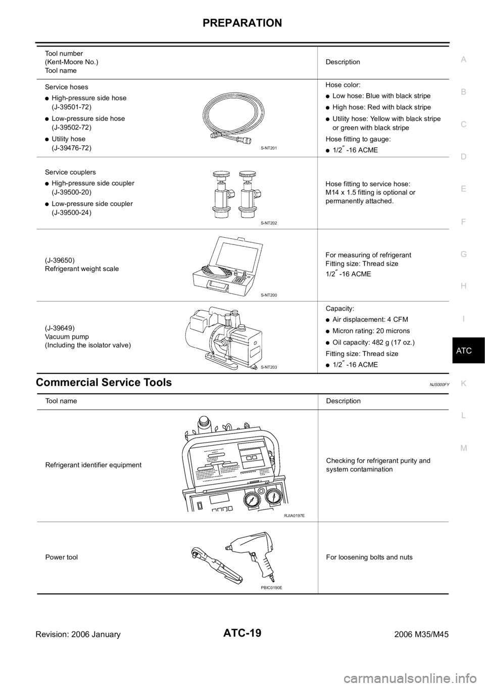
Service hoses
High-pressure side hose
(J-39501-72)
Low-pressure side hose
(J-39502-72)
Utility hose
(J-39476-72)Hose color:
Low hose: Blue with black stripe
High hose: Red with black stripe
Utility hose: Yellow with black stripe
or green with black stripe
Hose fitting to gauge:
1/2 -16 ACME
Service couplers
High-pressure side coupler
(J-39500-20)
Low-pressure side coupler
(J-39500-24)Hose fitting to service hose:
M14 x 1.5 fitting is optional or
permanently attached.
(J-39650)
Refrigerant weight scaleFor measuring of refrigerant
Fitting size: Thread size
1/2
-16 ACME
(J-39649)
Vacuum pump
(Including the isolator valve)Capacity:
Air displacement: 4 CFM
Micron rating: 20 microns
Oil capacity: 482 g (17 oz.)
Fitting size: Thread size
1/2 -16 ACME Tool number
(Kent-Moore No.)
Tool nameDescription
S-NT201
S-NT202
S-NT200
S-NT203
Tool nameDescription
Refrigerant identifier equipmentChecking for refrigerant purity and
system contamination
Power toolFor loosening bolts and nuts
RJIA0197E
PBIC0190E
Page 469 of 5621

ATC-22
REFRIGERATION SYSTEM
Revision: 2006 January2006 M35/M45
DESCRIPTION
General
The variable compressor is a swash plate type that changes piston stroke in response to the required cooling
capacity.
The tilt of the swash plate allows the piston’s stroke to change so that refrigerant discharge continuously
change from approx. 0 to 171 cm
3 (0 to 10.4 cu in).
RJIA4209E
Page 470 of 5621
REFRIGERATION SYSTEM
ATC-23
C
D
E
F
G
H
I
K
L
MA
B
AT C
Revision: 2006 January2006 M35/M45
Operation
1. Control Valve
–By changing high-pressure valve lift amount, built-in electronic control valve executes the following:
• Controls high-pressure valve discharge amount.
• Changes crankcase pressure in compressor.
• Changes angle of swash plate.
–Amount of high-pressure valve lift is determined by factors below.
• Low-pressure applied to diaphragm
• Spring load of set spring
• Balance of magnetic force generated in magnet coil
–Electronic control valve (ECV) magnet coil receives electric signal (duty control) from unified meter and A/
C amp. Then, magnetic force generated by electric current is changed to control high-pressure valve lift
amount.
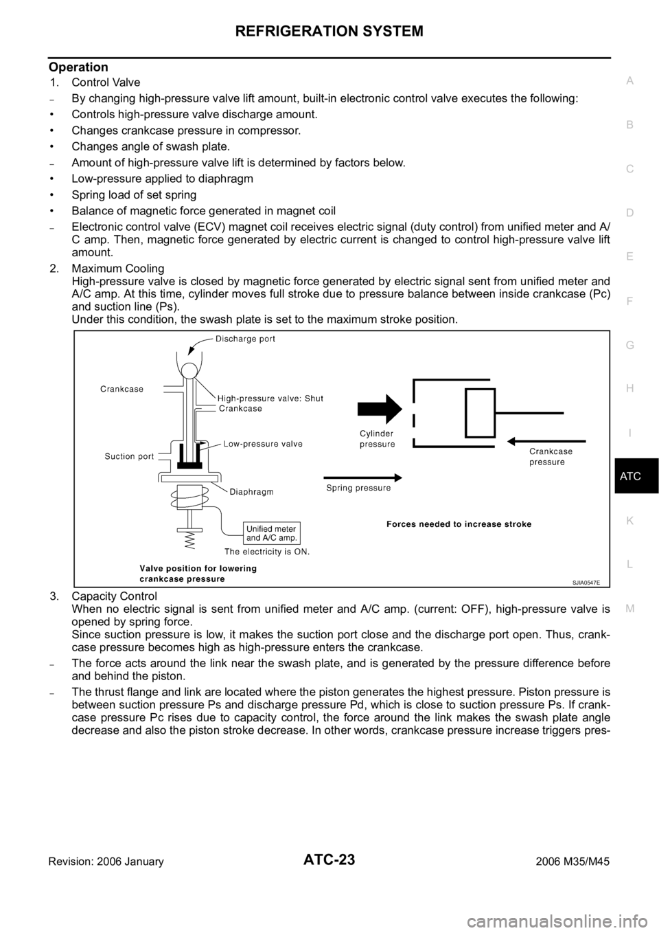
2. Maximum Cooling
High-pressure valve is closed by magnetic force generated by electric signal sent from unified meter and
A/C amp. At this time, cylinder moves full stroke due to pressure balance between inside crankcase (Pc)
and suction line (Ps).
Under this condition, the swash plate is set to the maximum stroke position.
3. Capacity Control
When no electric signal is sent from unified meter and A/C amp. (current: OFF), high-pressure valve is
opened by spring force.
Since suction pressure is low, it makes the suction port close and the discharge port open. Thus, crank-
case pressure becomes high as high-pressure enters the crankcase.
–The force acts around the link near the swash plate, and is generated by the pressure difference before
and behind the piston.
–The thrust flange and link are located where the piston generates the highest pressure. Piston pressure is
between suction pressure Ps and discharge pressure Pd, which is close to suction pressure Ps. If crank-
case pressure Pc rises due to capacity control, the force around the link makes the swash plate angle
decrease and also the piston stroke decrease. In other words, crankcase pressure increase triggers pres-
SJIA0547E
Page 621 of 5621
ATC-174
SERVICE DATA AND SPECIFICATIONS (SDS)
Revision: 2006 January2006 M35/M45
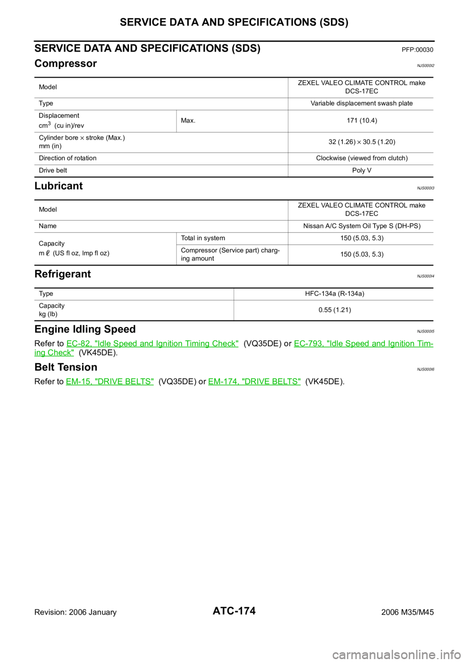
SERVICE DATA AND SPECIFICATIONS (SDS)PFP:00030
CompressorNJS000I2
LubricantNJS000I3
RefrigerantNJS000I4
Engine Idling SpeedNJS000I5
Refer to EC-82, "Idle Speed and Ignition Timing Check" (VQ35DE) or EC-793, "Idle Speed and Ignition Tim-
ing Check" (VK45DE).
Belt TensionNJS000I6
Refer to EM-15, "DRIVE BELTS" (VQ35DE) or EM-174, "DRIVE BELTS" (VK45DE).
ModelZEXEL VALEO CLIMATE CONTROL make
DCS-17EC
Ty p eVariable displacement swash plate
Displacement
cm
3 (cu in)/revMax. 171 (10.4)
Cylinder bore
stroke (Max.)
mm (in)32 (1.26) 30.5 (1.20)
Direction of rotationClockwise (viewed from clutch)
Drive beltPoly V
ModelZEXEL VALEO CLIMATE CONTROL make
DCS-17EC
NameNissan A/C System Oil Type S (DH-PS)
Capacity
m (US fl oz, lmp fl oz)Total in system 150 (5.03, 5.3)
Compressor (Service part) charg-
ing amount150 (5.03, 5.3)
Ty p eHFC-134a (R-134a)
Capacity
kg (lb)0.55 (1.21)
Page 1376 of 5621

CO-1
ENGINE COOLING SYSTEM
B ENGINE
CONTENTS
C
D
E
F
G
H
I
J
K
L
M
SECTION CO
A
CO
Revision: 2006 January2006 M35/M45
ENGINE COOLING SYSTEM
VQ35DE
PRECAUTIONS .......................................................... 3
Precautions for Supplemental Restraint System
(SRS) “AIR BAG” and “SEAT BELT PRE-TEN-
SIONER” .................................................................. 3
Precautions for Liquid Gasket .................................. 3
REMOVAL OF LIQUID GASKET SEALING .......... 3
LIQUID GASKET APPLICATION PROCEDURE ..... 3
PREPARATION ........................................................... 5
Special Service Tools ............................................... 5
Commercial Service Tools ........................................ 6
OVERHEATING CAUSE ANALYSIS .......................... 7
Troubleshooting Chart .............................................. 7
COOLING SYSTEM .................................................... 9
Cooling Circuit .......................................................... 9
System Chart ......................................................... 10
ENGINE COOLANT ...................................................11
Inspection ................................................................ 11
LEVEL CHECK .................................................... 11
LEAK CHECK ...................................................... 11
Changing Engine Coolant ....................................... 11
DRAINING ENGINE COOLANT .......................... 11
REFILLING ENGINE COOLANT ........................ 12
FLUSHING COOLING SYSTEM ......................... 13
RADIATOR ................................................................ 14
Components ........................................................... 14
Removal and Installation ........................................ 14
REMOVAL ........................................................
... 14
INSTALLATION ................................................... 16
INSPECTION AFTER INSTALLATION ............... 16
Checking Radiator Cap .......................................... 16
Checking Radiator .................................................. 16
RADIATOR (ALUMINUM TYPE) .............................. 18
Components ........................................................... 18
Disassembly and Assembly ................................... 18
PREPARATION ................................................... 18
DISASSEMBLY ................................................... 18
ASSEMBLY ......................................................... 19
INSPECTION ...................................................... 21COOLING FAN .......................................................... 22
Components ........................................................... 22
Removal and Installation ........................................ 22
REMOVAL ........................................................
... 22
INSTALLATION ................................................... 22
INSPECTION AFTER INSTALLATION ................ 22
Disassembly and Assembly .................................... 23
DISASSEMBLY ................................................... 23
INSPECTION AFTER DISASSEMBLY ................ 23
ASSEMBLY ......................................................... 23
WATER PUMP .......................................................... 24
Components ........................................................... 24
Removal and Installation ........................................ 24
REMOVAL ........................................................
... 24
INSPECTION AFTER REMOVAL ....................... 26
INSTALLATION ................................................... 26
INSPECTION AFTER INSTALLATION ................ 28
WATER INLET AND THERMOSTAT ASSEMBLY .... 29
Components ........................................................... 29
Removal and Installation ........................................ 29
REMOVAL ........................................................
... 29
INSPECTION AFTER REMOVAL ....................... 30
INSTALLATION ................................................... 30
INSPECTION AFTER INSTALLATION ................ 30
WATER OUTLET AND WATER PIPING ................... 31
Components ........................................................... 31
Removal and Installation ........................................ 31
REMOVAL ........................................................
... 31
INSTALLATION ................................................... 32
INSPECTION AFTER INSTALLATION ................ 32
SERVICE DATA AND SPECIFICATIONS (SDS) ...... 33
Standard and Limit .................................................. 33
ENGINE COOLANT CAPACITY (APPROXI-
MATE) .................................................................. 33
RADIATOR .......................................................
... 33
THERMOSTAT .................................................... 33
Page 1377 of 5621

CO-2Revision: 2006 January2006 M35/M45
VK45DE
PRECAUTIONS ......................................................... 34
Precautions for Supplemental Restraint System
(SRS) “AIR BAG” and “SEAT BELT PRE-TEN-
SIONER” ................................................................. 34
PREPARATION ......................................................... 35
Special Service Tools ............................................. 35
Commercial Service Tools ...................................... 35
OVERHEATING CAUSE ANALYSIS ........................ 36
Troubleshooting Chart ............................................ 36
COOLING SYSTEM .................................................. 38
Cooling Circuit ........................................................ 38
System Chart .......................................................... 39
ENGINE COOLANT .................................................. 40
Inspection ............................................................... 40
LEVEL CHECK .................................................... 40
LEAK CHECK ...................................................... 40
Changing Engine Coolant ....................................... 40
DRAINING ENGINE COOLANT .......................... 40
REFILLING ENGINE COOLANT ......................... 41
FLUSHING COOLING SYSTEM ......................... 42
RADIATOR ................................................................ 43
Components ........................................................... 43
Removal and Installation ........................................ 43
REMOVAL ........................................................
... 43
INSTALLATION .................................................... 45
INSPECTION AFTER INSTALLATION ................ 45
Checking Radiator Cap .......................................... 45
Checking Radiator .................................................. 45
RADIATOR (ALUMINUM TYPE) ............................... 47
Components ........................................................... 47
Disassembly and Assembly .................................... 47
PREPARATION ................................................... 47
DISASSEMBLY ................................................... 47
ASSEMBLY ......................................................... 48
INSPECTION ....................................................... 50COOLING FAN .......................................................... 51
Components ............................................................ 51
Removal and Installation ......................................... 51
REMOVAL ............................................................ 51
INSTALLATION .................................................... 51
INSPECTION AFTER INSTALLATION ................ 51
Disassembly and Assembly .................................... 52
DISASSEMBLY .................................................... 52
INSPECTION AFTER DISASSEMBLY ................ 52
ASSEMBLY .......................................................... 52
WATER PUMP ........................................................... 53
Components ............................................................ 53
Removal and Installation ......................................... 53
REMOVAL ............................................................ 53
INSPECTION AFTER REMOVAL ........................ 54
INSTALLATION .................................................... 54
INSPECTION AFTER INSTALLATION ................ 54
THERMOSTAT AND WATER CONTROL VALVE ..... 55
Components ............................................................ 55
Removal and Installation ......................................... 55
REMOVAL ............................................................ 55
INSPECTION AFTER REMOVAL ........................ 56
INSTALLATION .................................................... 56
INSPECTION AFTER INSTALLATION ................ 57
SERVICE DATA AND SPECIFICATIONS (SDS) ...... 58
Standard and Limit .................................................. 58
ENGINE COOLANT CAPACITY (APPROXI-
MATE) .................................................................. 58
RADIATOR ........................................................... 58
THERMOSTAT ..................................................... 58
WATER CONTROL VALVE .................................. 58