fuel INFINITI M35 2006 Factory Service Manual
[x] Cancel search | Manufacturer: INFINITI, Model Year: 2006, Model line: M35, Model: INFINITI M35 2006Pages: 5621, PDF Size: 65.56 MB
Page 1 of 5621

A
B
C
D
E
F
G
H
I
J
K
M
L
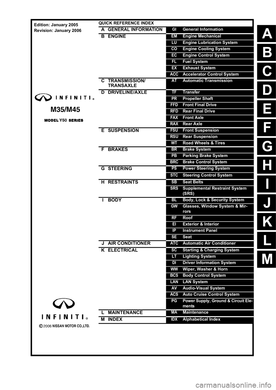
QUICK REFERENCE INDEX
AGENERAL INFORMATIONGIGeneral Information
BENGINEEMEngine Mechanical
LUEngine Lubrication System
COEngine Cooling System
ECEngine Control System
FLFuel System
EXExhaust System
ACCAccelerator Control System
CTRANSMISSION/
TRANSAXLEATAutomatic Transmission
DDRIVELINE/AXLETFTransfer
PRPropeller Shaft
FFDFront Final Drive
RFDRear Final Drive
FAXFront Axle
RAXRear Axle
ESUSPENSIONFSUFront Suspension
RSURear Suspension
WTRoad Wheels & Tires
FBRAKESBRBrake System
PBParking Brake System
BRCBrake Control System
GSTEERINGPSPower Steering System
STCSteering Control System
HRESTRAINTSSBSeat Belts
SRSSupplemental Restraint System
(SRS)
IBODYBLBody, Lock & Security System
GWGlasses, Window System & Mir-
rors
RFRoof
EIExterior & Interior
IPInstrument Panel
SESeat
JAIR CONDITIONERATCAutomatic Air Conditioner
KELECTRICALSCStarting & Charging System
LTLighting System
DIDriver Information System
WWWiper, Washer & Horn
BCSBody Control System
LANLAN System
AVAudio-Visual System
ACSAuto Cruise Control System
PGPower Supply, Ground & Circuit Ele-
ments
LMAINTENANCEMAMaintenance
MINDEXIDXAlphabetical Index
Edition: January 2005
Revision: January 2006
Page 4 of 5621

QUICK REFERENCE CHART M35/M45
* : Fuel, engine coolant and engine oil full. Spare tire, jack, hand tools and mats in designated positions.
REAR WHEEL ALIGNMENT (Unladen*)ELS0003Y
* : Fuel, engine coolant and engine oil full. Spare tire, jack, hand tools and mats in designated positions.
BRAKEELS0003Z
* : Under force of 490 N ( 50 kg, 110 lb ) with engine running.
REFILL CAPACITIESELS00040
Wheel turning
angle (Full turn)Inside
Degree minute
(Decimal degree)Minimum 36
20 (36.3)3945 (39.8)
Nominal 39
20 (39.3)4245 (42.8)
Maximum 40
20 (40.3)4345 (43.8)
Outside
Degree minute
(Decimal degree)Nominal 33
25 (33.4)33 20 (33.3)32 30 (32.5) Axle2WD AWD
Tire P245/45R18 245/40R19 245/45R18
Axle2WD AWD
Tire P245/45R18 245/40R19 245/45R18
Camber
Degree minute (Decimal degree)Minimum – 1
10 (– 1.17)– 1 20 (– 1.33)– 1 40 (– 0.67)
Nominal – 0
40 (– 0.67)– 0 50 (– 0.83)– 0 10 (– 0.17)
Maximum – 0
10 (– 0.17)– 0 20 (– 0.33) 0 20 (0.33 )
Total toe-inDistance ( A – B )Minimum 0.1 mm (0.004 in)
Nominal 2.8 mm (0.110 in)
Maximum 5.5 mm (0.217 in)
Angle (left plus right )
Degree minute
(Decimal degree)Minimum 0
(0)
Nominal 7
(0.12)
Maximum 14
(0.23)
Front brake Pad wear limit 2.0 mm (0.079 in)
Rotor repair limit 26.0 mm (1.024 in)
Rear brake Pad wear limit 2.0 mm (0.079 in)
Rotor repair limit 14.0 mm (0.551 in)
Pedal free height 157 - 167 mm (6.18 - 6.57 in)
Pedal depressed height* 90 mm (3.54 in) or more
UNITLiter US measure
Fuel tank76 20 gal
Coolant ( With reservoir tank )VQ35DE 8.9 9 - 3/8 qt
VK45DE 10.4 11 qt
Engine (VQ35DE)Drain and refill
With oil filter change 4.7 5 qt
Without oil filter change 4.4 4 - 5/8 qt
Dry engine (Overhaul) 5.4 5 - 3/4 qt
Engine (VK45DE)Drain and refill
With oil filter change 5.5 5 - 3/4 qt
Without oil filter change 4.9 5 - 1/8 qt
Dry engine (Overhaul) 6.7 7 - 1/8 qt
2006
Page 22 of 5621
![INFINITI M35 2006 Factory Service Manual LASER BEAM AIMING ADJUSTMENT
ACS-13
[ICC]
C
D
E
F
G
H
I
J
L
MA
B
ACS
Revision: 2006 January2006 M35/M45
LASER BEAM AIMING ADJUSTMENTPFP:00026
OutlineNKS004CM
Adjust the laser beam aiming every time th INFINITI M35 2006 Factory Service Manual LASER BEAM AIMING ADJUSTMENT
ACS-13
[ICC]
C
D
E
F
G
H
I
J
L
MA
B
ACS
Revision: 2006 January2006 M35/M45
LASER BEAM AIMING ADJUSTMENTPFP:00026
OutlineNKS004CM
Adjust the laser beam aiming every time th](/img/42/57023/w960_57023-21.png)
LASER BEAM AIMING ADJUSTMENT
ACS-13
[ICC]
C
D
E
F
G
H
I
J
L
MA
B
ACS
Revision: 2006 January2006 M35/M45
LASER BEAM AIMING ADJUSTMENTPFP:00026
OutlineNKS004CM
Adjust the laser beam aiming every time the ICC sensor integrated unit is removed or installed.
CAUTION:
Adjust laser beam aiming at a horizontal place as far as 12 m (39 ft) forward the vehicle can be
seen.
Adjust laser beam aiming 5 seconds after starting engine.
Never view ICC sensor integrated unit body window directly during laser beam aiming adjustment.
Follow the CONSULT-II when adjusting the laser beam aiming (laser beam aiming adjustment can-
not be operated without CONSULT-II).
Never ride on vehicle during laser beam aiming adjustment.
Idle and turn headlamps OFF during laser beam aiming adjustment.
PreparationNKS004CN
Adjust the tire pressure to the specified value.
See that there is no load in the vehicle.
Coolant, engine oil filled up to correct level and full fuel tank.
Shift the gear into “P” position and release the parking brake.
Clean the ICC sensor integrated unit with a soft cloth.
Remove the front bumper grille. Refer to EI-13, "Removal and
Installation of Front Bumper Grille" .
Outline of Adjustment ProcedureNKS004CO
1. Set up the ICC target board [KV99110100 (J-45718)].
2. Adjust the sensor following the procedure on CONSULT-II. (Turn manually the screw for up-down position
adjustment. ICC sensor integrated unit automatically adjust the right-left position.)
Setting the ICC Target BoardNKS004CP
Accurate ICC target board setting is required for the laser beam aiming adjustment.
CAUTION:
ICC system does not function normally if laser beam aiming is not accurate.
ADJUSTING HEIGHT OF THE TARGET
1. Attach a triangle scale at 28 mm (1.10 in) below the center.
PKIB8350E
PKIB8351E
Page 86 of 5621

PRECAUTIONS
AT-7
D
E
F
G
H
I
J
K
L
MA
B
AT
Revision: 2006 January2006 M35/M45
PRECAUTIONSPFP:00001
Precautions for Supplemental Restraint System (SRS) “AIR BAG” and “SEAT
BELT PRE-TENSIONER”
NCS001JC
The Supplemental Restraint System such as “AIR BAG” and “SEAT BELT PRE-TENSIONER”, used along
with a front seat belt, helps to reduce the risk or severity of injury to the driver and front passenger for certain
types of collision. This system includes seat belt switch inputs and dual stage front air bag modules. The SRS
system uses the seat belt switches to determine the front air bag deployment, and may only deploy one front
air bag, depending on the severity of a collision and whether the front occupants are belted or unbelted.
Information necessary to service the system safely is included in the SRS and SB section of this Service Man-
ual.
WAR NING :
To avoid rendering the SRS inoperative, which could increase the risk of personal injury or death
in the event of a collision which would result in air bag inflation, all maintenance must be per-
formed by an authorized NISSAN/INFINITI dealer.
Improper maintenance, including incorrect removal and installation of the SRS, can lead to per-
sonal injury caused by unintentional activation of the system. For removal of Spiral Cable and Air
Bag Module, see the SRS section.
Do not use electrical test equipment on any circuit related to the SRS unless instructed to in this
Service Manual. SRS wiring harnesses can be identified by yellow and/or orange harnesses or
harness connectors.
Precautions for On Board Diagnostic (OBD) System of A/T and EngineNCS001JD
The ECM has an on board diagnostic system. It will light up the malfunction indicator lamp (MIL) to warn the
driver of a malfunction causing emission deterioration.
CAUTION:
Be sure to turn the ignition switch OFF and disconnect the battery cable from the negative termi-
nal before any repair or inspection work. The open/short circuit of related switches, sensors, sole-
noid valves, etc. will cause the MIL to light up.
Be sure to connect and lock the connectors securely after work. A loose (unlocked) connector will
cause the MIL to light up due to an open circuit. (Be sure the connector is free from water, grease,
dirt, bent terminals, etc.)
Be sure to route and secure the harnesses properly after work. Interference of the harness with a
bracket, etc. may cause the MIL to light up due to a short circuit.
Be sure to connect rubber tubes properly after work. A misconnected or disconnected rubber tube
may cause the MIL to light up due to a malfunction of the EGR system or fuel injection system, etc.
Be sure to erase the unnecessary malfunction information (repairs completed) from the TCM and
ECM before returning the vehicle to the customer.
Page 116 of 5621

A/T CONTROL SYSTEM
AT-37
D
E
F
G
H
I
J
K
L
MA
B
AT
Revision: 2006 January2006 M35/M45
Lock-up ControlNCS001JU
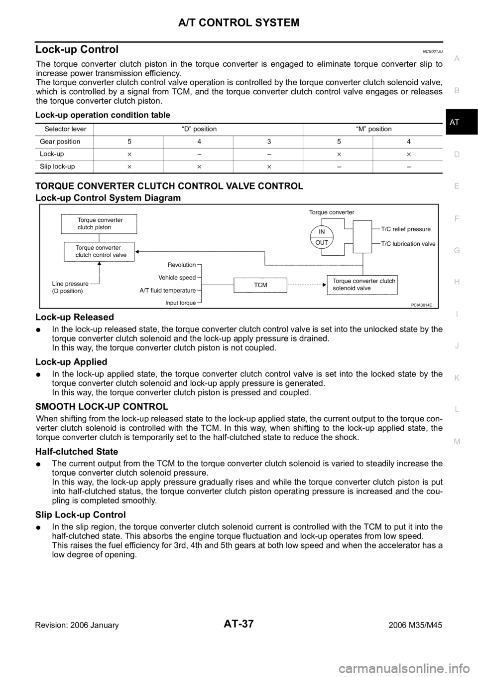
The torque converter clutch piston in the torque converter is engaged to eliminate torque converter slip to
increase power transmission efficiency.
The torque converter clutch control valve operation is controlled by the torque converter clutch solenoid valve,
which is controlled by a signal from TCM, and the torque converter clutch control valve engages or releases
the torque converter clutch piston.
Lock-up operation condition table
TORQUE CONVERTER CLUTCH CONTROL VALVE CONTROL
Lock-up Control System Diagram
Lock-up Released
In the lock-up released state, the torque converter clutch control valve is set into the unlocked state by the
torque converter clutch solenoid and the lock-up apply pressure is drained.
In this way, the torque converter clutch piston is not coupled.
Lock-up Applied
In the lock-up applied state, the torque converter clutch control valve is set into the locked state by the
torque converter clutch solenoid and lock-up apply pressure is generated.
In this way, the torque converter clutch piston is pressed and coupled.
SMOOTH LOCK-UP CONTROL
When shifting from the lock-up released state to the lock-up applied state, the current output to the torque con-
verter clutch solenoid is controlled with the TCM. In this way, when shifting to the lock-up applied state, the
torque converter clutch is temporarily set to the half-clutched state to reduce the shock.
Half-clutched State
The current output from the TCM to the torque converter clutch solenoid is varied to steadily increase the
torque converter clutch solenoid pressure.
In this way, the lock-up apply pressure gradually rises and while the torque converter clutch piston is put
into half-clutched status, the torque converter clutch piston operating pressure is increased and the cou-
pling is completed smoothly.
Slip Lock-up Control
In the slip region, the torque converter clutch solenoid current is controlled with the TCM to put it into the
half-clutched state. This absorbs the engine torque fluctuation and lock-up operates from low speed.
This raises the fuel efficiency for 3rd, 4th and 5th gears at both low speed and when the accelerator has a
low degree of opening.
Selector lever “D” position “M” position
Gear position 5 4 3 5 4
Lock-up
––
Slip lock-up––
PCIA0014E
Page 120 of 5621

ON BOARD DIAGNOSTIC (OBD) SYSTEM
AT-41
D
E
F
G
H
I
J
K
L
MA
B
AT
Revision: 2006 January2006 M35/M45
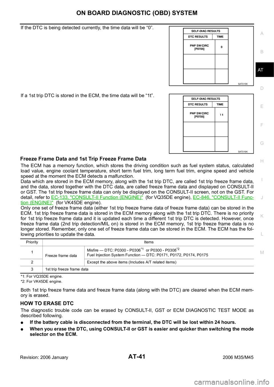
If the DTC is being detected currently, the time data will be “0”.
If a 1st trip DTC is stored in the ECM, the time data will be “1t”.
Freeze Frame Data and 1st Trip Freeze Frame Data
The ECM has a memory function, which stores the driving condition such as fuel system status, calculated
load value, engine coolant temperature, short term fuel trim, long term fuel trim, engine speed and vehicle
speed at the moment the ECM detects a malfunction.
Data which are stored in the ECM memory, along with the 1st trip DTC, are called 1st trip freeze frame data,
and the data, stored together with the DTC data, are called freeze frame data and displayed on CONSULT-II
or GST. The 1st trip freeze frame data can only be displayed on the CONSULT-II screen, not on the GST. For
detail, refer to EC-133, "
CONSULT-II Function (ENGINE)" (for VQ35DE engine), EC-846, "CONSULT-II Func-
tion (ENGINE)" (for VK45DE engine).
Only one set of freeze frame data (either 1st trip freeze frame data of freeze frame data) can be stored in the
ECM. 1st trip freeze frame data is stored in the ECM memory along with the 1st trip DTC. There is no priority
for 1st trip freeze frame data and it is updated each time a different 1st trip DTC is detected. However, once
freeze frame data (2nd trip detection/MIL on) is stored in the ECM memory, 1st trip freeze frame data is no
longer stored. Remember, only one set of freeze frame data can be stored in the ECM. The ECM has the fol-
lowing priorities to update the data.
*1: For VQ35DE engine.
*2: For VK45DE engine.
Both 1st trip freeze frame data and freeze frame data (along with the DTC) are cleared when the ECM mem-
ory is erased.
HOW TO ERASE DTC
The diagnostic trouble code can be erased by CONSULT-II, GST or ECM DIAGNOSTIC TEST MODE as
described following.
If the battery cable is disconnected from the terminal, the DTC will be lost within 24 hours.
When you erase the DTC, using CONSULT-II or GST is easier and quicker than switching the mode
selector on the ECM.
SAT015K
SAT016K
Priority Items
1
Freeze frame dataMisfire — DTC: P0300 - P0306
*1 or P0300 - P0308*2
Fuel Injection System Function — DTC: P0171, P0172, P0174, P0175
2 Except the above items (Includes A/T related items)
3 1st trip freeze frame data
Page 629 of 5621
![INFINITI M35 2006 Factory Service Manual AV-8
[WITHOUT MOBILE ENTERTAINMENT SYSTEM]
SYSTEM DESCRIPTION
Revision: 2006 January2006 M35/M45
SYSTEM DESCRIPTIONPFP:00000
System FunctionsNKS00489
Here is an example of functions. For details, refe INFINITI M35 2006 Factory Service Manual AV-8
[WITHOUT MOBILE ENTERTAINMENT SYSTEM]
SYSTEM DESCRIPTION
Revision: 2006 January2006 M35/M45
SYSTEM DESCRIPTIONPFP:00000
System FunctionsNKS00489
Here is an example of functions. For details, refe](/img/42/57023/w960_57023-628.png)
AV-8
[WITHOUT MOBILE ENTERTAINMENT SYSTEM]
SYSTEM DESCRIPTION
Revision: 2006 January2006 M35/M45
SYSTEM DESCRIPTIONPFP:00000
System FunctionsNKS00489
Here is an example of functions. For details, refer to the owner's manual or navigation system owner's manual.
AUDIO
Speed Sensitive Volume (for BASE System)
Volume level of this system gone up and down automatically in proportion to the vehicle speed. And the
control level can be selected by the customer.
The audio unit inputs the vehicle signal that is sent from unified meter and A/C amp via CAN communica-
tion through AV (NAVI) control unit.
Precision Phased Audio (for BASE System)
It plays back the sound using the woofer (ultra-low bass and clear midrange sound) and reproduces the
sound with presence.
When the conventional BASS/TREBLE adjustment is a maximum, the sounds might be unclear because
the volume of midrange sound also rises together with the bass and treble. The precision phased audio
can emphasize ultra-low bass and ultra-high treble without changing the midrange sound by digital pro-
cessing using DSP.
NOTE:
When the radio is played, the noise may increase more than the presence due to the characteristics of
broadcasting waves. Therefore, the amplification rate while playing the radio is controlled lower than the
rate while playing CD.
AudioPilot® (for BOSE System)
AudioPilot® is the sound improving system that picks up any noises and the sound of music coming into the
vehicle by a microphone under the steering, and that the BOSE amp revises the frequency feature of music at
real time in response to the frequency feature of the noise while driving and listening to music.
If low frequency area noise from vehicle is loud, it adjusts low frequency element of music to be bigger
than vehicle noise.
If high frequency area noise from vehicle is loud, it adjusts all frequency element of music to be bigger
than vehicle noise.
Centerpoint® (for BOSE Surround 5.1ch System)
CD and 2.0ch DVD stereo sound played at audio unit and DVD player are subjected to signal processing in
BOSE amp. It can play the surround sound with presence.
VEHICLE INFORMATION SYSTEM
The status of audio, climate control system, fuel consumption, and navigation system (if equipped) are
displayed.
AV (NAVI) control unit receives the data signal from ECM, unified meter and A/C amp and low tire pres-
sure warning control unit via CAN communication. It calculates the values of fuel economy, tire pressure,
and trip computer from the received information and displays them.
NAVIGATION SYSTEM
Location Detection Principle
The navigation system periodically calculates the vehicle's current
position according to the following three signals:
Travel distance of the vehicle as determined by the vehicle
speed sensor
Turning angle of the vehicle as determined by the gyroscope
(angular velocity sensor)
Direction of vehicle travel as determined by the GPS antenna
(GPS information)
The current position of the vehicle is then identified by comparing the
calculated vehicle position with map data read from the map DVD-
ROM, which is stored in the DVD-ROM drive (map-matching), and
SKIB1058E
Page 767 of 5621
![INFINITI M35 2006 Factory Service Manual AV-146
[WITH MOBILE ENTERTAINMENT SYSTEM]
SYSTEM DESCRIPTION
Revision: 2006 January2006 M35/M45
SYSTEM DESCRIPTIONPFP:00000
System FunctionsNKS004AB
Here is an example of functions. For details, refer INFINITI M35 2006 Factory Service Manual AV-146
[WITH MOBILE ENTERTAINMENT SYSTEM]
SYSTEM DESCRIPTION
Revision: 2006 January2006 M35/M45
SYSTEM DESCRIPTIONPFP:00000
System FunctionsNKS004AB
Here is an example of functions. For details, refer](/img/42/57023/w960_57023-766.png)
AV-146
[WITH MOBILE ENTERTAINMENT SYSTEM]
SYSTEM DESCRIPTION
Revision: 2006 January2006 M35/M45
SYSTEM DESCRIPTIONPFP:00000
System FunctionsNKS004AB
Here is an example of functions. For details, refer to the owner's manual or navigation system owner's manual.
AUDIO
AudioPilot
® (for BOSE System)
AudioPilot® is the sound improving system that picks up any noises and the sound of music coming into the
vehicle by a microphone under the steering, and that the BOSE amp revises the frequency feature of music at
real time in response to the frequency feature of the noise while driving and listening to music.
If low frequency area noise from vehicle is loud, it adjusts low frequency element of music to be bigger
than vehicle noise.
If high frequency area noise from vehicle is loud, it adjusts all frequency element of music to be bigger
than vehicle noise.
Centerpoint® (for BOSE Surround 5.1ch System)
CD and 2.0ch DVD stereo sound played at audio unit and DVD player are subjected to signal processing in
BOSE amp. It can play the surround sound with presence.
VEHICLE INFORMATION SYSTEM
The status of audio, climate control system, fuel consumption, and navigation system (if equipped) are
displayed.
AV (NAVI) control unit receives the data signal from ECM, unified meter and A/C amp and low tire pres-
sure warning control unit via CAN communication. It calculates the values of fuel economy, tire pressure,
and trip computer from the received information and displays them.
NAVIGATION SYSTEM
Location Detection Principle
The navigation system periodically calculates the vehicle's current
position according to the following three signals:
Travel distance of the vehicle as determined by the vehicle
speed sensor
Turning angle of the vehicle as determined by the gyroscope
(angular velocity sensor)
Direction of vehicle travel as determined by the GPS antenna
(GPS information)
The current position of the vehicle is then identified by comparing the
calculated vehicle position with map data read from the map DVD-
ROM, which is stored in the DVD-ROM drive (map-matching), and
indicated on the screen as a vehicle mark. More accurate data is judged and used by comparing vehicle posi-
tion detection results found by the GPS with the result by map-matching.
The current vehicle position will be calculated by detecting the dis-
tance the vehicle moved from the previous calculation point and its
direction.
Travel distance
Travel distance calculations are based on the vehicle speed
sensor input signal. Therefore, the calculation may become
incorrect as the tires wear down. To prevent this, an automatic
distance correction function has been adopted.
Travel direction
Change in the travel direction of the vehicle is calculated by a
gyroscope (angular velocity sensor) and a GPS antenna (GPS
information). They have both advantages and disadvantages.
SKIB1058E
SEL684V
Page 940 of 5621

BL-1
BODY, LOCK & SECURITY SYSTEM
I BODY
CONTENTS
C
D
E
F
G
H
J
K
L
M
SECTION BL
A
B
BL
Revision: 2006 January2006 M35/M45
BODY, LOCK & SECURITY SYSTEM
PRECAUTIONS .......................................................... 6
Precautions for Supplemental Restraint System
(SRS) “AIR BAG” and “SEAT BELT PRE-TEN-
SIONER” .................................................................. 6
Precautions for Procedures without Cowl Top Cover ..... 6
Precautions Necessary for Steering Wheel Rotation
after Battery Disconnect ........................................... 6
OPERATION PROCEDURE ................................. 6
Precautions for Work ...........................................
..... 7
PREPARATION ........................................................... 8
Special Service Tools ............................................... 8
Commercial Service Tools ........................................ 8
SQUEAK AND RATTLE TROUBLE DIAGNOSIS ...... 9
Work Flow ................................................................ 9
CUSTOMER INTERVIEW ..................................... 9
DUPLICATE THE NOISE AND TEST DRIVE ..... 10
CHECK RELATED SERVICE BULLETINS ......... 10
LOCATE THE NOISE AND IDENTIFY THE
ROOT CAUSE .................................................... 10
REPAIR THE CAUSE ......................................... 10
CONFIRM THE REPAIR ...................................... 11
Generic Squeak and Rattle Troubleshooting .......... 11
INSTRUMENT PANEL ......................................... 11
CENTER CONSOLE ............................................ 11
DOORS ................................................................ 11
TRUNK ................................................................ 12
SUNROOF/HEADLINING ................................... 12
SEATS ................................................................. 12
UNDERHOOD ..................................................... 12
Diagnostic Worksheet ............................................ 13
HOOD ....................................................................... 15
Fitting Adjustment .................................................. 15
Removal and Installation of Hood Assembly .......... 17
REMOVAL ........................................................
... 17
INSTALLETION ................................................... 18
Removal and Installation of Hood Lock Control ..... 18
REMOVAL ........................................................
... 18
INSTALLATION ................................................... 19
Hood Lock Control Inspection ................................ 20RADIATOR CORE SUPPORT .................................. 21
Removal and Installation ........................................ 21
REMOVAL ........................................................
... 21
INSTALLATION ................................................... 22
FRONT FENDER ................................................... ... 23
Removal and Installation ........................................ 23
REMOVAL ........................................................
... 23
INSTALLATION ................................................... 23
POWER DOOR LOCK SYSTEM .............................. 24
Component Parts and Harness Connector Location ... 24
System Description ................................................. 25
DOOR LOCK ACTUATOR OPERATION ............. 26
FUEL LID OPERATION ....................................... 26
OUTLINE ............................................................. 26
CAN Communication System Description .............. 26
CAN Communication Unit ....................................... 26
Schematic ............................................................... 27
Wiring Diagram —D/LOCK— ................................. 28
Terminals and Reference Value of BCM ................. 31
Work Flow ............................................................... 31
CONSULT-II Function (BCM) ................................. 32
CONSULT-II INSPECTION PROCEDURE .......... 32
CONSULT-II APPLICATION ITEMS .................... 33
Trouble Diagnosis Chart by Symptom .................... 34
Power Supply and Ground Circuit Check of BCM ... 35
Check Door Lock and Unlock Switch ..................... 36
Check Door Lock Actuator/Driver Side ................... 38
Check Door Lock Actuator/Passenger Side ........... 39
Check Door Lock Actuator/Rear LH ....................... 40
Check Door Lock Actuator/Rear RH ....................... 40
Check Fuel Lid Opener Actuator ............................ 41
Door Key Cylinder Switch Check ............................ 42
INTELLIGENT KEY SYSTEM ................................... 44
Component Parts and Harness Connector Location ... 44
System Description ................................................. 48
DOOR LOCK/UNLOCK/TRUNK OPEN FUNC-
TION .................................................................... 48
REMOTE KEYLESS ENTRY FUNCTIONS ......... 52
ENGINE START FUNCTION ............................... 54
WARNING FUNCTION ........................................ 55
Page 963 of 5621

BL-24
POWER DOOR LOCK SYSTEM
Revision: 2006 January2006 M35/M45
POWER DOOR LOCK SYSTEMPFP:24814
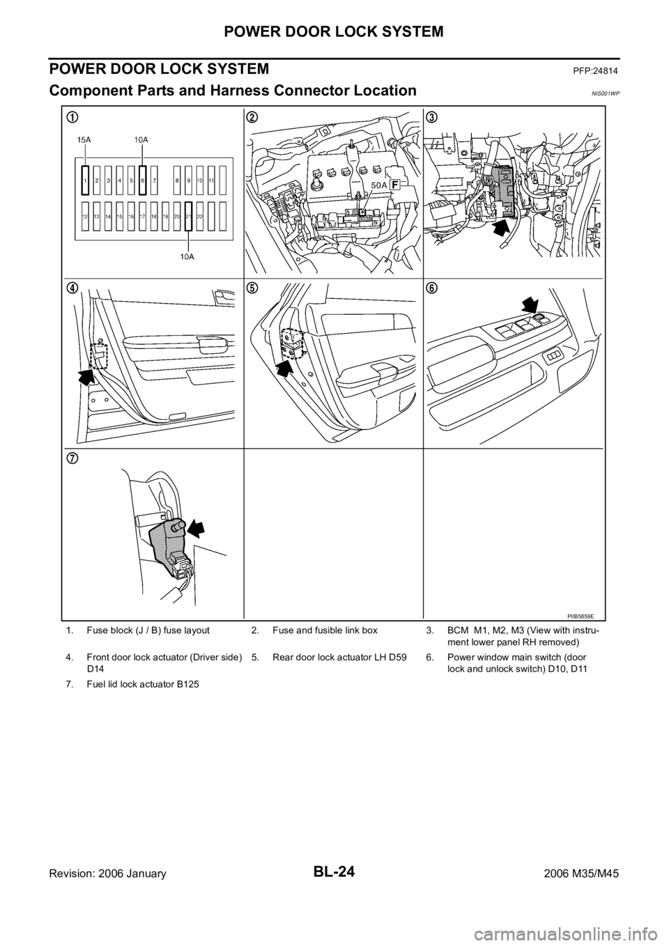
Component Parts and Harness Connector LocationNIS001WP
1. Fuse block (J / B) fuse layout 2. Fuse and fusible link box 3. BCM M1, M2, M3 (View with instru-
ment lower panel RH removed)
4. Front door lock actuator (Driver side)
D145. Rear door lock actuator LH D59 6. Power window main switch (door
lock and unlock switch) D10, D11
7. Fuel lid lock actuator B125
PIIB5859E