warning light INFINITI M35 2006 Factory Service Manual
[x] Cancel search | Manufacturer: INFINITI, Model Year: 2006, Model line: M35, Model: INFINITI M35 2006Pages: 5621, PDF Size: 65.56 MB
Page 18 of 5621
![INFINITI M35 2006 Factory Service Manual DESCRIPTION
ACS-9
[ICC]
C
D
E
F
G
H
I
J
L
MA
B
ACS
Revision: 2006 January2006 M35/M45
ICC System DisplayNKS004CK
The status of ICC system is displayed by dot matrix LCD, MAIN switch indicator lamp and INFINITI M35 2006 Factory Service Manual DESCRIPTION
ACS-9
[ICC]
C
D
E
F
G
H
I
J
L
MA
B
ACS
Revision: 2006 January2006 M35/M45
ICC System DisplayNKS004CK
The status of ICC system is displayed by dot matrix LCD, MAIN switch indicator lamp and](/img/42/57023/w960_57023-17.png)
DESCRIPTION
ACS-9
[ICC]
C
D
E
F
G
H
I
J
L
MA
B
ACS
Revision: 2006 January2006 M35/M45
ICC System DisplayNKS004CK
The status of ICC system is displayed by dot matrix LCD, MAIN switch indicator lamp and ICC system warning
lamp on the combination meter.
IN VEHICLE-TO-VEHICLE DISTANCE CONTROL MODE
IN CONVENTIONAL (FIXED SPEED) CRUISE CONTROL
MODE
PKIB8347E
No. Display items Description
1 Set vehicle speed indicator Indicates the set vehicle speed.
2 Vehicle ahead detection indicator Indicates whether it detects a vehicle ahead.
3 Set distance indicatorIndicates the selected distance between vehicles set with the DISTANCE
switch.
4 Own vehicle indicator Indicates the base vehicle.
5 MAIN switch indicator lamp (Green) Indicates that the MAIN switch is ON.
6Intelligent cruise control system warning
lamp (Orange)The light comes on if there is a malfunction in the ICC system.
PKIB4982J
No. Display items Description
1 Set switch indicatorIndicates that the set conventional (fixed speed) cruise control mode is con-
trolled.
2 MAIN switch indicator lamp (Green) Indicates that the MAIN switch is ON.
3Intelligent cruise control system warning
lamp (Orange)The light comes on if there is a malfunction in the ICC system.
Page 122 of 5621

ON BOARD DIAGNOSTIC (OBD) SYSTEM
AT-43
D
E
F
G
H
I
J
K
L
MA
B
AT
Revision: 2006 January2006 M35/M45
HOW TO ERASE DTC (WITH GST)
1. If the ignition switch stays ON after repair work, be sure to turn ignition switch OFF once. Wait at least 10
seconds and then turn it ON (engine stopped) again.
2. Perform AT-103, "
OBD-II SELF-DIAGNOSTIC PROCEDURE (WITH GST)" . (The engine warm-up step
can be skipped when performing the diagnosis only to erase the DTC.)
3. Select Mode 4 with GST (Generic Scan Tool). For details, refer to EC-146, "
Generic Scan Tool (GST)
Function" (for VQ35DE engine), EC-859, "Generic Scan Tool (GST) Function" (for VK45DE engine).
HOW TO ERASE DTC (NO TOOLS)
The A/T CHECK indicator lamp is located on the instrument panel.
1. If the ignition switch stays ON after repair work, be sure to turn ignition switch OFF once. Wait at least 10
seconds and then turn it ON (engine stopped) again.
2. Perform AT-103, "
TCM SELF-DIAGNOSTIC PROCEDURE (NO TOOLS)" . (The engine warm-up step
can be skipped when performing the diagnosis only to erase the DTC.)
3. Perform “OBD-II SELF-DIAGNOSTIC PROCEDURE (No tools)”. Refer to EC-67, "
How to Erase DTC"
(for VQ35DE engine), EC-778, "How to Erase DTC" (for VK45DE engine).
Malfunction Indicator Lamp (MIL)NCS001K1
DESCRIPTION
The MIL is located on the combination meters.
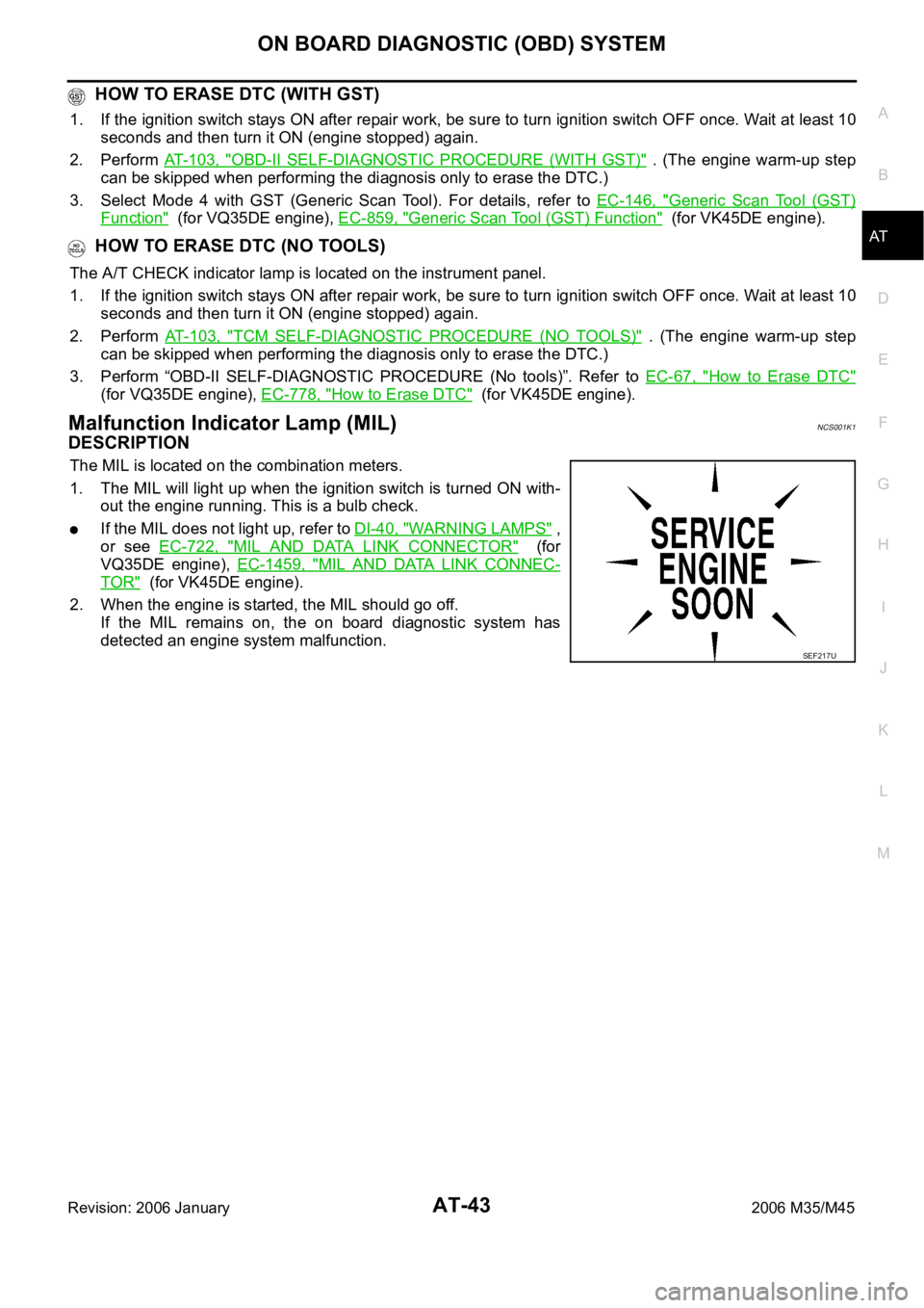
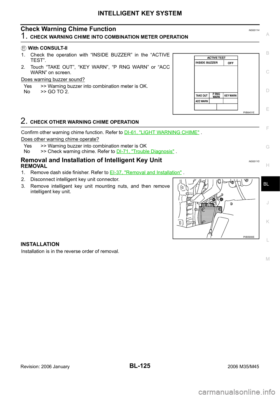
1. The MIL will light up when the ignition switch is turned ON with-
out the engine running. This is a bulb check.
If the MIL does not light up, refer to DI-40, "WARNING LAMPS" ,
or see EC-722, "
MIL AND DATA LINK CONNECTOR" (for
VQ35DE engine), EC-1459, "
MIL AND DATA LINK CONNEC-
TOR" (for VK45DE engine).
2. When the engine is started, the MIL should go off.
If the MIL remains on, the on board diagnostic system has
detected an engine system malfunction.
SEF217U
Page 929 of 5621

BCS-8
BCM (BODY CONTROL MODULE)
Revision: 2006 January2006 M35/M45
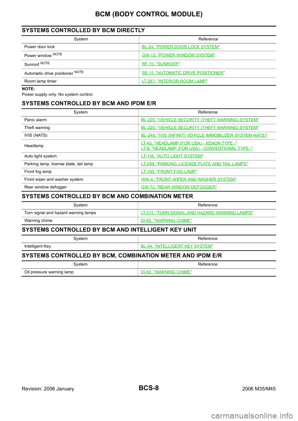
SYSTEMS CONTROLLED BY BCM DIRECTLY
NOTE:
Power supply only. No system control.
SYSTEMS CONTROLLED BY BCM AND IPDM E/R
SYSTEMS CONTROLLED BY BCM AND COMBINATION METER
SYSTEMS CONTROLLED BY BCM AND INTELLIGENT KEY UNIT
SYSTEMS CONTROLLED BY BCM, COMBINATION METER AND IPDM E/R
System Reference
Power door lockBL-24, "
POWER DOOR LOCK SYSTEM"
Power window NOTEGW-13, "POWER WINDOW SYSTEM"
Sunroof NOTERF-10, "SUNROOF"
Automatic drive positioner NOTESE-11, "AUTOMATIC DRIVE POSITIONER"
Room lamp timerLT-267, "INTERIOR ROOM LAMP"
System Reference
Panic alarmBL-220, "
VEHICLE SECURITY (THEFT WARNING) SYSTEM"
Theft warningBL-220, "VEHICLE SECURITY (THEFT WARNING) SYSTEM"
IVIS (NATS)BL-248, "IVIS (INFINITI VEHICLE IMMOBILIZER SYSTEM-NATS)"
HeadlampLT- 4 3 , "HEADLAMP (FOR USA) - XENON TYPE -"
LT- 8 , "HEADLAMP (FOR USA) - CONVENTIONAL TYPE -"
Auto light systemLT- 11 6 , "AUTO LIGHT SYSTEM"
Parking lamp, license plate, tail lampLT-249, "PARKING, LICENSE PLATE AND TAIL LAMPS"
Front fog lampLT-193, "FRONT FOG LAMP"
Front wiper and washer systemWW-4, "FRONT WIPER AND WASHER SYSTEM"
Rear window defoggerGW-73, "REAR WINDOW DEFOGGER"
System Reference
Turn signal and hazard warning lampsLT- 2 11 , "
TURN SIGNAL AND HAZARD WARNING LAMPS"
Warning chimeDI-60, "WARNING CHIME"
System Reference
Intelligent KeyBL-44, "
INTELLIGENT KEY SYSTEM"
System Reference
Oil pressure warning lampDI-60, "
WARNING CHIME"
Page 930 of 5621

BCM (BODY CONTROL MODULE)
BCS-9
C
D
E
F
G
H
I
J
L
MA
B
BCS
Revision: 2006 January2006 M35/M45
MAJOR COMPONENTS AND CONTROL SYSTEM
NOTE:
*1: Functions only when the Intelligent Key is inserted in key slot.
*2: With navigation system
*3: Without navigation systemSystem Input Output
Intelligent Key system Intelligent Key unit
All door locking actuator
Trunk lid opener actuator
Turn signal lamp (LH, RH)
Combination meter
Power door lock system
Power window main switch (door lock and unlock switch)
Power window sub switch (passenger side)
(door lock and unlock switch)All-door locking actuator
Power supply (IGN) to power win-
dow, sunroofIgnition power supply Power window and sunroof system
Power supply (BAT) to power
window, sunroof and power seatBattery power supplyPower window, sunroof system and
power seat
Panic alarm
Key slot
Intelligent KeyIPDM E/R
Theft warning system
All-door switch
Hood switch
Intelligent Key
Power window main switch (door lock and unlock switch)
IPDM E/R
Security indicator lamp
Auto light system
Optical sensor
Combination switchIPDM E/R
Battery saver control
Ignition switch
Combination switchIPDM E/R
Headlamp
Tail lamp
Front fog lampCombination switch IPDM E/R
Turn signal lamp Combination switch
Turn signal lamp
Combination meter
Hazard lamp Hazard switch
Turn signal lamp
Combination meter
Room lamp timer
Key switch
Power window main switch (door lock and unlock switch)
Front door switch driver side
All-door switchInterior room lamp
Key warning chime*
1Key switch
Front door switch driver sideCombination meter (warning buzzer)
Light warning chime
Combination switch
Front door switch driver sideCombination meter (warning buzzer)
Seat belt warning chime
Combination meter [Seat belt buckle (driver side) switch]
Ignition switchCombination meter (warning buzzer)
Vehicle-speed-sensing intermit-
tent wiper
Combination switch
Unified meter and A/C amp.IPDM E/R
Rear window defogger
Multifunction switch
NAVI control unit*2
AV control unit*3
IPDM E/R
Page 1064 of 5621

INTELLIGENT KEY SYSTEM
BL-125
C
D
E
F
G
H
J
K
L
MA
B
BL
Revision: 2006 January2006 M35/M45
Check Warning Chime FunctionNIS001Y4
1. CHECK WARNING CHIME INTO COMBINATION METER OPERATION
With CONSULT-II
1. Check the operation with “INSIDE BUZZER” in the “ACTIVE
TEST”.
2. Touch “TAKE OUT”, “KEY WARN”, “P RNG WARN” or “ACC
WARN” on screen.
Does warning buzzer sound?
Yes >> Warning buzzer into combination meter is OK.
No >> GO TO 2.
2. CHECK OTHER WARNING CHIME OPERATION
Confirm other warning chime function. Refer to DI-61, "
LIGHT WARNING CHIME" .
Does other warning chime operate?
Yes >> Warning buzzer into combination meter is OK
No >> Check warning chime. Refer to DI-71, "
Trouble Diagnosis" .
Removal and Installation of Intelligent Key UnitNIS001Y5
REMOVAL
1. Remove dash side finisher. Refer to EI-37, "Removal and Installation" .
2. Disconnect intelligent key unit connector.
3. Remove intelligent key unit mounting nuts, and then remove
intelligent key unit.
INSTALLATION
Installation is in the reverse order of removal.
PIIB6451E
PIIB5900E
Page 1186 of 5621

VEHICLE SECURITY (THEFT WARNING) SYSTEM
BL-247
C
D
E
F
G
H
J
K
L
MA
B
BL
Revision: 2006 January2006 M35/M45
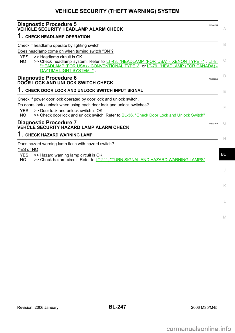
Diagnostic Procedure 5NIS00209
VEHICLE SECURITY HEADLAMP ALARM CHECK
1. CHECK HEADLAMP OPERATION
Check if headlamp operate by lighting switch.
Does headlamp come on when turning switch
“ON”?
YES >> Headlamp circuit is OK.
NO >> Check headlamp system. Refer to LT- 4 3 , "
HEADLAMP (FOR USA) - XENON TYPE -" , LT- 8 ,
"HEADLAMP (FOR USA) - CONVENTIONAL TYPE -" or LT- 7 9 , "HEADLAMP (FOR CANADA) -
DAYTIME LIGHT SYSTEM -" .
Diagnostic Procedure 6NIS0020A
DOOR LOCK AND UNLOCK SWITCH CHECK
1. CHECK DOOR LOCK AND UNLOCK SWITCH INPUT SIGNAL
Check if power door lock operated by door lock and unlock switch.
Do doors lock / unlock when using each door lock and unlock switches?
YES >> Door lock and unlock switch is OK.
NO >> Check door lock and unlock switch. Refer to BL-36, "
Check Door Lock and Unlock Switch"
Diagnostic Procedure 7NIS0020B
VEHCLE SECURITY HAZARD LAMP ALARM CHECK
1. CHECK HAZARD WARNING LAMP
Does hazard warning lamp flash with hazard switch?
YES or NO
YES >> Hazard warning lamp circuit is OK.
NO >> Check hazard circuit. Refer to LT- 2 11 , "
TURN SIGNAL AND HAZARD WARNING LAMPS" .
Page 1315 of 5621
![INFINITI M35 2006 Factory Service Manual BRC-4
[VDC/TCS/ABS]
PRECAUTIONS
Revision: 2006 January2006 M35/M45
Precautions for Brake ControlNFS000Q1
Just after starting vehicle after ignition switch ON, brake pedal may vibrate or motor operatin INFINITI M35 2006 Factory Service Manual BRC-4
[VDC/TCS/ABS]
PRECAUTIONS
Revision: 2006 January2006 M35/M45
Precautions for Brake ControlNFS000Q1
Just after starting vehicle after ignition switch ON, brake pedal may vibrate or motor operatin](/img/42/57023/w960_57023-1314.png)
BRC-4
[VDC/TCS/ABS]
PRECAUTIONS
Revision: 2006 January2006 M35/M45
Precautions for Brake ControlNFS000Q1
Just after starting vehicle after ignition switch ON, brake pedal may vibrate or motor operating noise may
be heard from engine compartment. This is normal condition.
When an error is indicated by ABS or another warning lamp, collect all necessary information from cus-
tomer (what symptoms are present under what conditions) and check for simple causes before starting
diagnostic servicing. Besides electrical system inspection, check brake booster operation, brake fluid
level, and oil leaks.
If tire size and type are used in an improper combination, or brake pads are not Genuine NISSAN parts,
stopping distance or steering stability may deteriorate.
ABS might be out of order or malfunctions by putting a radio (wiring inclusive), an antenna and a lead-in
wire near the control unit.
If aftermarket parts (car stereo, CD player, etc.) have been installed, check for incidents such as harness
pinches, open circuits, and improper wiring.
VDC system may not operate normally or a VDC OFF indicator lamp or SLIP indicator lamp may light.
–When replacing the following parts with parts other than genuine parts or making modifications: Suspen-
sion-related parts (shock absorber, spring, bushing, etc.), tires, wheels (other than specified sizes), brake-
related parts (pad, rotor, caliper, etc.), engine-related parts (muffler, ECM, etc.) and body reinforcement-
related parts (roll bar, tower bar, etc.).
–When driving with worn or deteriorated suspension, tires and brake-related parts.
Page 1319 of 5621
![INFINITI M35 2006 Factory Service Manual BRC-8
[VDC/TCS/ABS]
SYSTEM DESCRIPTION
Revision: 2006 January2006 M35/M45
from 4 wheel sensors. When ABS actuator and electric unit (control unit) detects a spin at drive wheels
(rear wheels), INFINITI M35 2006 Factory Service Manual BRC-8
[VDC/TCS/ABS]
SYSTEM DESCRIPTION
Revision: 2006 January2006 M35/M45
from 4 wheel sensors. When ABS actuator and electric unit (control unit) detects a spin at drive wheels
(rear wheels),](/img/42/57023/w960_57023-1318.png)
BRC-8
[VDC/TCS/ABS]
SYSTEM DESCRIPTION
Revision: 2006 January2006 M35/M45
from 4 wheel sensors. When ABS actuator and electric unit (control unit) detects a spin at drive wheels
(rear wheels), it compares wheel speed signals from all 4 wheels. At this time, LH and RH rear brake fluid
pressure are controlled, while fuel being cut to engine and throttle valve being closed to reduce engine
torque by the control unit. Further more, throttle position is continuously controlled to ensure the optimum
engine torque at all times.
During TCS operation, it informs driver of system operation by flashing SLIP indicator lamp.
Electrical system diagnosis by CONSULT-II is available.
VDC
Vehicle Dynamics Control system detects driver's steering operation amount and brake pedal travel from
steering angle sensor and pressure sensor. Using information from yaw rate/side G sensor and wheel
sensor, VDC judges driving condition (conditions of under steer and over steer) to improve vehicle driving
stability by controlling brake application to 4 wheels and engine output.
During VDC operation, it informs driver of system operation by flashing SLIP indicator lamp.
Electrical system diagnosis by CONSULT-II is available.
ECD
Receives deceleration degree commandment value signal from ICC sensor integrated unit, and controls brake
fluid pressure with the motor (built-in ABS actuator and electric unit (control unit)).
Operation That Is Not "System Error" NFS000Q7
ABS
When starting engine or just after starting vehicle, brake pedal may vibrate or the motor operating sound
may be heard from engine room. This is a normal states of the operation check.
During ABS operation, brake pedal lightly vibrates and a mechanical sound may be heard. This is normal.
Stopping distance may be longer than that of vehicles without ABS when vehicle drives on rough, gravel,
or snow-covered (fresh, deep snow) roads.
TCS
Depending on road circumstances, driver may have a sluggish feel. This is normal, because optimum
traction has highest priority under TCS operation.
When vehicle is passing through a road where surface friction varies, downshifting or depressing acceler-
ator pedal fully may activate TCS temporarily.
VDC
During VDC operation, body and brake pedal lightly vibrate and mechanical sounds may be heard. This is
normal.
If vehicle is rotated on turn table, or rolled and rocked on ship, ABS warning lamp, VDC OFF indicator
lamp, and SLIP indicator lamp may turn on. In this case, start engine on normal road again. If ABS warn-
ing lamp, VDC OFF indicator lamp, and SLIP indicator lamp turn off after restart, it is normal.
When starting TCS or VDC under rapid acceleration or hard turn, operating sound by brake pedal is gen-
erated. However, this is not malfunction. This is because TCS and VDC are functioning normally.
VDC may not operate normally or ABS warning lamp, VDC OFF indicator lamp and SLIP indicator lamp
may turn on when driving special roads with extremely steep slant (banks on circuit road and so on.) How-
ever, it is not malfunction when returning to a normal state after restarting the engine. In that case, be sure
to erase the memory of self-diagnosis. Refer to BRC-23, "
ERASE MEMORY" .
Yaw rate /side G sensor malfunction may occur under hard turn like spin turn, rapid acceleration turn, drift
run, etc., when VDC function is OFF (VDC OFF switch is turned on). It is not malfunction if it is possible to
return to a normal position after restarting engine. Then erase the memory of self-diagnosis. Refer to
BRC-23, "
ERASE MEMORY" .
VDC OFF indicator lamp and SLIP indicator lamp may simultaneously turn on when low tire pressure
warning lamp turns on. This is not a VDC system error but results from characteristic change of tires.
Fail-Safe FunctionNFS000Q8
ABS, EBD SYSTEM
In the event there is a malfunction with the electrical system, the ABS warning lamp, VDC OFF indicator lamp,
and SLIP indicator lamp will turn on when it is the ABS that is malfunctioning, and the brake warning lamp,
ABS warning lamp, VDC OFF indicator lamp, and SLIP indicator lamp will turn on when it is the EBD that is
Page 1366 of 5621
![INFINITI M35 2006 Factory Service Manual TROUBLE DIAGNOSIS
BRC-55
[VDC/TCS/ABS]
C
D
E
G
H
I
J
K
L
MA
B
BRC
Revision: 2006 January2006 M35/M45
Symptom 3 The Braking Distance Is LongNFS000R6
CAUTION:
The stopping distance on slippery road INFINITI M35 2006 Factory Service Manual TROUBLE DIAGNOSIS
BRC-55
[VDC/TCS/ABS]
C
D
E
G
H
I
J
K
L
MA
B
BRC
Revision: 2006 January2006 M35/M45
Symptom 3 The Braking Distance Is LongNFS000R6
CAUTION:
The stopping distance on slippery road](/img/42/57023/w960_57023-1365.png)
TROUBLE DIAGNOSIS
BRC-55
[VDC/TCS/ABS]
C
D
E
G
H
I
J
K
L
MA
B
BRC
Revision: 2006 January2006 M35/M45
Symptom 3 The Braking Distance Is LongNFS000R6
CAUTION:
The stopping distance on slippery road surfaces might be longer with the ABS operating than when
the ABS is not operating.
1. CHECK FUNCTION
Turn ignition switch OFF and disconnect ABS actuator and electric unit (control unit) connector to deactivate
ABS. In this condition, check stopping distance. After inspection, connect connector.
OK or NG
OK >> GO TO procedure 3 “CHECK WHEEL SENSOR AND SENSOR ROTOR” of symptom 1. Refer to
BRC-53, "
Symptom 1 Excessive ABS Function Operation Frequency" .
NG >> Check brake system.
Symptom 4 ABS Function Does Not OperateNFS000R7
CAUTION:
ABS does not operate when speed is 10 km/h (6 MPH) or lower.
1. CHECK ABS WARNING LAMP DISPLAY
Make sure that the ABS warning lamp turns OFF after ignition switch is turned on or when driving.
OK or NG
OK >> GO TO procedure 3 “CHECK WHEEL SENSOR AND SENSOR ROTOR” of symptom 1. Refer to
BRC-53, "
Symptom 1 Excessive ABS Function Operation Frequency" .
NG >> Perform self-diagnosis. Refer to BRC-23, "
Self-Diagnosis" .
Symptom 5 Pedal Vibration or ABS Operation Sound OccursNFS000R8
CAUTION:
Under the following conditions, ABS is activated and vibration is felt when brake pedal is lightly
depressed (just place a foot on it).However, this is normal.
When shifting gears
When driving on slippery road
During cornering at high speed
When passing over bumps or grooves [at approximately 50 mm (1.97 in) or more]
When pulling away just after starting engine [at approximately 10 km/h (6 MPH) or higher]
1. SYMPTOM CHECK 1
Check if there is pedal vibration or operation sound when the engine is started.
Do symptoms occur?
YES >> GO TO 2.
NO >> Perform self -diagnosis. Refer to BRC-23, "
Self-Diagnosis" .
2. SYMPTOM CHECK 2
Check symptoms when electrical component (headlamps, etc.) switches are operated.
Do symptoms occur?
YES >> Check if there is a radio, antenna, antenna lead wire, or wiring close to the control unit. If there is,
move it farther away.
NO >> GO TO procedure 3 “CHECK WHEEL SENSOR AND SENSOR ROTOR” of symptom 1. Refer to
BRC-53, "
Symptom 1 Excessive ABS Function Operation Frequency" .
Page 1435 of 5621

DI-2Revision: 2006 January2006 M35/M45 A/T INDICATOR ........................................................ 56
System Description ................................................. 56
MANUAL MODE .................................................. 56
NOT MANUAL MODE ......................................... 56
Wiring Diagram — AT/IND — ................................. 57
A/T Indicator Is Malfunction .................................... 59
WARNING CHIME .................................................. ... 60
System Description ................................................. 60
POWER SUPPLY AND GROUND CIRCUIT ....... 60
IGNITION KEY WARNING CHIME (WITH INTEL-
LIGENT KEY) ...................................................... 61
LIGHT WARNING CHIME ................................... 61
SEAT BELT WARNING CHIME ........................... 61
Component Parts and Harness Connector Location ... 62
Schematic ............................................................... 63
Wiring Diagram — CHIME — ................................. 64
Terminals and Reference Value for Combination
Meter ...................................................................... 67
Terminals and Reference Value for Unified Meter
and A/C Amp. ......................................................... 67
Terminals and Reference Value for BCM ................ 68
CONSULT-II Function (BCM) .................................. 69
CONSULT-II BASIC OPERATION ....................... 69
DATA MONITOR .................................................. 70
ACTIVE TEST ..................................................... 71
SELF-DIAG RESULTS ........................................ 71
CONSULT-II Function (METER A/C AMP) ............. 71
Trouble Diagnosis ................................................... 71
HOW TO PERFORM TROUBLE DIAGNOSIS .... 71
PRELIMINARY INSPECTION ............................. 71
SYMPTOM CHART ............................................. 72
Meter Buzzer Circuit Inspection .............................. 72
Lighting Switch Signal Inspection ........................... 73
Front Door Switch (Driver Side) Signal Inspection ... 73
Seat Belt Buckle Switch Signal Inspection ............. 74
Electrical Component Inspection ............................ 76
FRONT DOOR SWITCH (DRIVER SIDE) ........... 76
SEAT BELT BUCKLE SWITCH (DRIVER SIDE) ... 76
CAN COMMUNICATION ........................................... 77
System Description ................................................. 77
CAN Communication Unit ....................................... 77
LANE DEPARTURE WARNING SYSTEM ................ 78
Precautions for Lane Departure Warning (LDW)
system .................................................................... 78
System Description ................................................. 78
LDW SYSTEM OPERATION ............................... 78
POWER SUPPLY AND GROUND CIRCUIT ....... 80
Action Test ...........................................................
... 80
LDW SYSTEM RUNNING TEST ......................... 80
Camera Aiming Adjustment .................................... 81
OUTLINE ............................................................. 81
PREPARATION ................................................... 81TARGET SETTING .............................................. 81
VEHICLE HEIGHT CHECK ................................. 84
AIMING ADJUSTMENT ....................................... 84
Component Parts and Harness Connector Location ... 88
Wiring Diagram — LDW — ..................................... 89
Terminals and Reference Value for LDW Camera
Unit .......................................................................... 91
CONSULT-II Function (LDW) .................................. 91
DESCRIPTION .................................................... 91
CONSULT-II BASIC OPERATION ....................... 91
WORK SUPPORT ............................................... 92
SELF-DIAG RESULTS ......................................... 92
DATA MONITOR .................................................. 93
ACTIVE TEST ...................................................... 94
Trouble Diagnosis ................................................... 95
HOW TO PERFORM TROUBLE DIAGNOSIS .... 95
PRELIMINARY INSPECTION .............................. 95
SYMPTOM CHART .............................................. 96
Power Supply and Ground Circuit Inspection ......... 96
DTC [C1B00] CAMERA UNIT MALF ...................... 97
DTC [C1B01] CAM AIMING INCMP ....................... 97
DTC [C1B02] VHCL SPD DATA MALF ................... 97
DTC [C1B03] ABNRML TEMP DETECT ................ 97
DTC [U1000] CAN COMM CIRCUIT ...................... 98
DTC [U1010] CONTROL UNIT (CAN) .................... 98
LDW Chime Circuit Inspection ................................ 98
LDW Switch Circuit Inspection ................................ 99
LDW Indicator Lamp Circuit Inspection .................102
Turn Signal Input Inspection .................................103
Electrical Component Inspection ..........................103
LDW SWITCH ....................................................103
Removal and Installation for LDW Camera Unit ...103
REMOVAL ..........................................................103
INSTALLATION ..................................................103
Removal and Installation for LDW Chime .............104
REMOVAL ..........................................................104
INSTALLATION ..................................................104
Removal and Installation for LDW Switch .............104
COMPASS ...............................................................105
System Description ...............................................105
DIRECTION DISPLAY .......................................105
Zone Variation Change Procedure ........................105
Correction Functions of the Compass Display ......105
AUTOMATIC CORRECTION .............................105
MANUAL CORRECTION PROCEDURE ...........105
Wiring Diagram – COMPAS – ...............................106
Removal and Installation of Compass ...................107
CLOCK ....................................................................108
Wiring Diagram — CLOCK — ...............................108
Removal and Installation of Clock .........................109
REMOVAL ..........................................................109
INSTALLATION ..................................................109