pressure INFINITI M35 2006 Factory Owners Manual
[x] Cancel search | Manufacturer: INFINITI, Model Year: 2006, Model line: M35, Model: INFINITI M35 2006Pages: 5621, PDF Size: 65.56 MB
Page 459 of 5621

ATC-12
PRECAUTIONS
Revision: 2006 January2006 M35/M45
WAR NING :
Make sure all refrigerant is discharged into the recycling equipment and the pressure in the system is
less than atmospheric pressure. Then gradually loosen the discharge side hose fitting and remove it.
CAUTION:
When replacing or cleaning refrigerant cycle components, observe the following.
When the compressor is removed, store it in the same way at it is when mounted on the car. Fail-
ure to do so will cause lubricant to enter the low-pressure chamber.
When connecting tubes, always use a torque wrench and a back-up wrench.
After disconnecting tubes, immediately plug all openings to prevent entry of dirt and moisture.
When installing an air conditioner in the vehicle, connect the pipes at the final stage of the opera-
tion. Never remove the seal caps of pipes and other components until just before required for con-
nection.
Allow components stored in cool areas to warm to working area temperature before removing seal
caps. This prevents condensation from forming inside A/C components.
Thoroughly remove moisture from the refrigeration system before charging the refrigerant.
Always replace used O-rings.
When connecting tubes, apply lubricant to circle of the O-rings shown in illustration. Be careful
not to apply lubricant to threaded portion.
O-ring must be closely attached to the groove of tube.
When replacing the O-ring, be careful not to damage O-ring and tube.
Connect tube until a click can be heard, then tighten the nut or bolt by hand until snug. Make sure
that the O-ring is installed to tube correctly.
After connecting line, perform leak test and make sure that there is no leakage from connections.
When the refrigerant leaking point is found, disconnect that line and replace the O-ring. Then
tighten connections of seal seat to the specified torque.
Precautions for Servicing CompressorNJS000FT
Plug all openings to prevent moisture and foreign matter from entering.
When the compressor is removed, store it in the same way at it is when mounted on the car.
When replacing or repairing compressor, follow “Maintenance of Lubricant Quantity in Compres-
sor” exactly. Refer to ATC-26, "
Maintenance of Lubricant Quantity in Compressor" .
Keep friction surfaces between clutch and pulley clean. If the surface is contaminated with lubri-
cant, wipe it off by using a clean waste cloth moistened with thinner. Lubricant name : Nissan A/C System Oil Type S
RHA861F
Page 463 of 5621

ATC-16
PREPARATION
Revision: 2006 January2006 M35/M45
PREPARATIONPFP:00002
Special Service ToolsNJS000FW
The actual shapes of Kent-Moore tools may differ from those of special service tools illustrated here.
Tool number
(Kent-Moore No.)
Tool nameDescription
9253089908
(for high-pressure pipe 1)
(-)
9253089912
(for high-pressure flexible hose)
(-)
9253089916
(for low-pressure pipe 1 and
low-pressure flexible hose)
(-)
Disconnector tool set
(J-45815)Disconnect one-touch joint connection
SJIA1274E
Page 466 of 5621
PREPARATION
ATC-19
C
D
E
F
G
H
I
K
L
MA
B
AT C
Revision: 2006 January2006 M35/M45
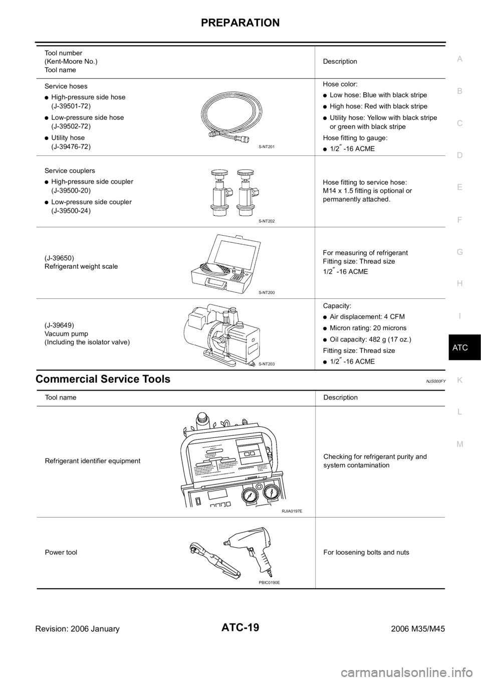
Commercial Service ToolsNJS000FY
Service hoses
High-pressure side hose
(J-39501-72)
Low-pressure side hose
(J-39502-72)
Utility hose
(J-39476-72)Hose color:
Low hose: Blue with black stripe
High hose: Red with black stripe
Utility hose: Yellow with black stripe
or green with black stripe
Hose fitting to gauge:
1/2 -16 ACME
Service couplers
High-pressure side coupler
(J-39500-20)
Low-pressure side coupler
(J-39500-24)Hose fitting to service hose:
M14 x 1.5 fitting is optional or
permanently attached.
(J-39650)
Refrigerant weight scaleFor measuring of refrigerant
Fitting size: Thread size
1/2
-16 ACME
(J-39649)
Vacuum pump
(Including the isolator valve)Capacity:
Air displacement: 4 CFM
Micron rating: 20 microns
Oil capacity: 482 g (17 oz.)
Fitting size: Thread size
1/2 -16 ACME Tool number
(Kent-Moore No.)
Tool nameDescription
S-NT201
S-NT202
S-NT200
S-NT203
Tool nameDescription
Refrigerant identifier equipmentChecking for refrigerant purity and
system contamination
Power toolFor loosening bolts and nuts
RJIA0197E
PBIC0190E
Page 467 of 5621
ATC-20
REFRIGERATION SYSTEM
Revision: 2006 January2006 M35/M45
REFRIGERATION SYSTEMPFP:KA990
Refrigerant CycleNJS000FZ
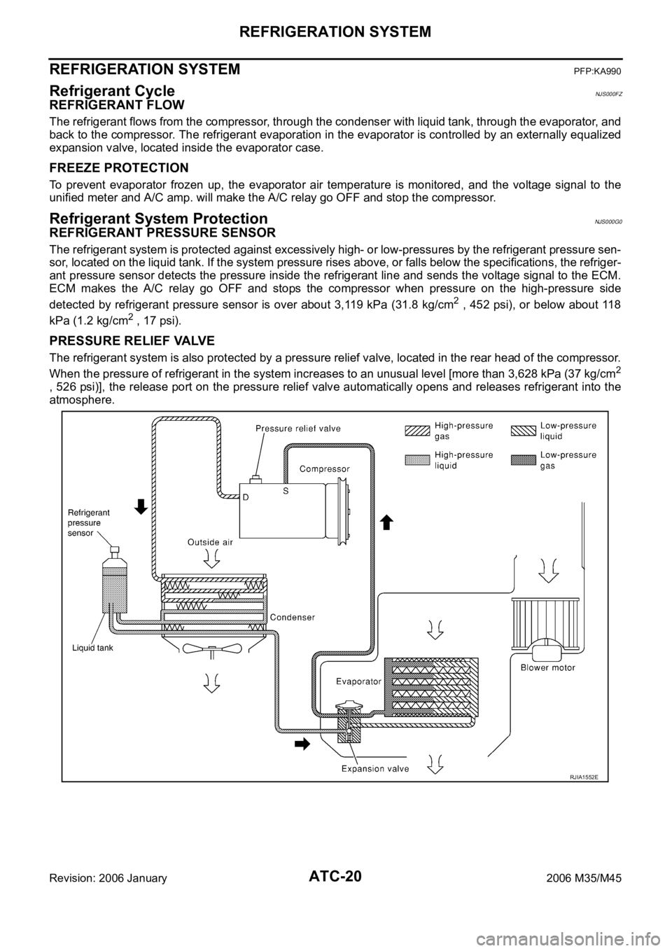
REFRIGERANT FLOW
The refrigerant flows from the compressor, through the condenser with liquid tank, through the evaporator, and
back to the compressor. The refrigerant evaporation in the evaporator is controlled by an externally equalized
expansion valve, located inside the evaporator case.
FREEZE PROTECTION
To prevent evaporator frozen up, the evaporator air temperature is monitored, and the voltage signal to the
unified meter and A/C amp. will make the A/C relay go OFF and stop the compressor.
Refrigerant System ProtectionNJS000G0
REFRIGERANT PRESSURE SENSOR
The refrigerant system is protected against excessively high- or low-pressures by the refrigerant pressure sen-
sor, located on the liquid tank. If the system pressure rises above, or falls below the specifications, the refriger-
ant pressure sensor detects the pressure inside the refrigerant line and sends the voltage signal to the ECM.
ECM makes the A/C relay go OFF and stops the compressor when pressure on the high-pressure side
detected by refrigerant pressure sensor is over about 3,119 kPa (31.8 kg/cm
2 , 452 psi), or below about 118
kPa (1.2 kg/cm
2 , 17 psi).
PRESSURE RELIEF VALVE
The refrigerant system is also protected by a pressure relief valve, located in the rear head of the compressor.
When the pressure of refrigerant in the system increases to an unusual level [more than 3,628 kPa (37 kg/cm
2
, 526 psi)], the release port on the pressure relief valve automatically opens and releases refrigerant into the
atmosphere.
RJIA1552E
Page 468 of 5621

REFRIGERATION SYSTEM
ATC-21
C
D
E
F
G
H
I
K
L
MA
B
AT C
Revision: 2006 January2006 M35/M45
Variable Displacement CompressorNJS000G1
GENERAL INFORMATION
1. The variable compressor provides refrigerant control under varying conditions. During cold winters, it may
not produce high refrigerant pressure discharge (compared to previous units) when used with air condi-
tioning systems.
2. For air conditioning systems with the compressor, the clutch remains engaged unless: the system main
switch, fan switch or ignition switch is turned OFF. When ambient (outside) temperatures are low or when
the amount of refrigerant is insufficient, the clutch is disengaged to protect the compressor.
Page 470 of 5621
REFRIGERATION SYSTEM
ATC-23
C
D
E
F
G
H
I
K
L
MA
B
AT C
Revision: 2006 January2006 M35/M45
Operation
1. Control Valve
–By changing high-pressure valve lift amount, built-in electronic control valve executes the following:
• Controls high-pressure valve discharge amount.
• Changes crankcase pressure in compressor.
• Changes angle of swash plate.
–Amount of high-pressure valve lift is determined by factors below.
• Low-pressure applied to diaphragm
• Spring load of set spring
• Balance of magnetic force generated in magnet coil
–Electronic control valve (ECV) magnet coil receives electric signal (duty control) from unified meter and A/
C amp. Then, magnetic force generated by electric current is changed to control high-pressure valve lift
amount.
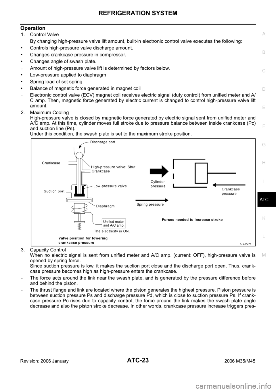
2. Maximum Cooling
High-pressure valve is closed by magnetic force generated by electric signal sent from unified meter and
A/C amp. At this time, cylinder moves full stroke due to pressure balance between inside crankcase (Pc)
and suction line (Ps).
Under this condition, the swash plate is set to the maximum stroke position.
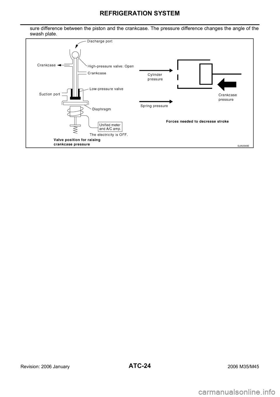
3. Capacity Control
When no electric signal is sent from unified meter and A/C amp. (current: OFF), high-pressure valve is
opened by spring force.
Since suction pressure is low, it makes the suction port close and the discharge port open. Thus, crank-
case pressure becomes high as high-pressure enters the crankcase.
–The force acts around the link near the swash plate, and is generated by the pressure difference before
and behind the piston.
–The thrust flange and link are located where the piston generates the highest pressure. Piston pressure is
between suction pressure Ps and discharge pressure Pd, which is close to suction pressure Ps. If crank-
case pressure Pc rises due to capacity control, the force around the link makes the swash plate angle
decrease and also the piston stroke decrease. In other words, crankcase pressure increase triggers pres-
SJIA0547E
Page 471 of 5621
ATC-24
REFRIGERATION SYSTEM
Revision: 2006 January2006 M35/M45
sure difference between the piston and the crankcase. The pressure difference changes the angle of the
swash plate.
SJIA0548E
Page 474 of 5621
LUBRICANT
ATC-27
C
D
E
F
G
H
I
K
L
MA
B
AT C
Revision: 2006 January2006 M35/M45
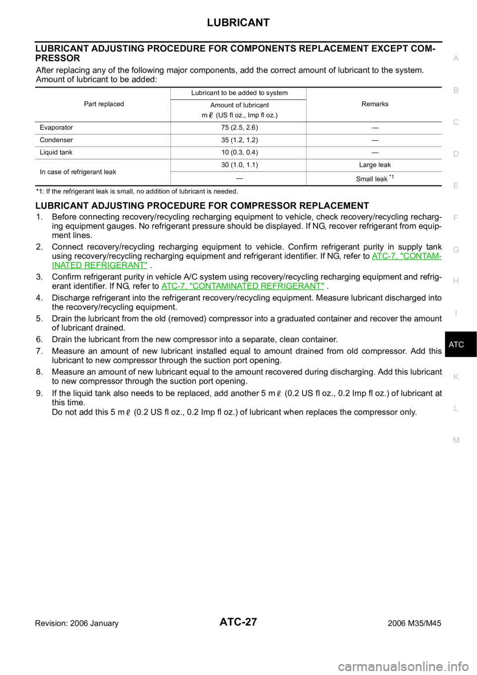
LUBRICANT ADJUSTING PROCEDURE FOR COMPONENTS REPLACEMENT EXCEPT COM-
PRESSOR
After replacing any of the following major components, add the correct amount of lubricant to the system.
Amount of lubricant to be added:
*1: If the refrigerant leak is small, no addition of lubricant is needed.
LUBRICANT ADJUSTING PROCEDURE FOR COMPRESSOR REPLACEMENT
1. Before connecting recovery/recycling recharging equipment to vehicle, check recovery/recycling recharg-
ing equipment gauges. No refrigerant pressure should be displayed. If NG, recover refrigerant from equip-
ment lines.
2. Connect recovery/recycling recharging equipment to vehicle. Confirm refrigerant purity in supply tank
using recovery/recycling recharging equipment and refrigerant identifier. If NG, refer to ATC-7, "
CONTAM-
INATED REFRIGERANT" .
3. Confirm refrigerant purity in vehicle A/C system using recovery/recycling recharging equipment and refrig-
erant identifier. If NG, refer to ATC-7, "
CONTAMINATED REFRIGERANT" .
4. Discharge refrigerant into the refrigerant recovery/recycling equipment. Measure lubricant discharged into
the recovery/recycling equipment.
5. Drain the lubricant from the old (removed) compressor into a graduated container and recover the amount
of lubricant drained.
6. Drain the lubricant from the new compressor into a separate, clean container.
7. Measure an amount of new lubricant installed equal to amount drained from old compressor. Add this
lubricant to new compressor through the suction port opening.
8. Measure an amount of new lubricant equal to the amount recovered during discharging. Add this lubricant
to new compressor through the suction port opening.
9. If the liquid tank also needs to be replaced, add another 5 m (0.2 US fl oz., 0.2 Imp fl oz.) of lubricant at
this time.
Do not add this 5 m (0.2 US fl oz., 0.2 Imp fl oz.) of lubricant when replaces the compressor only.
Part replacedLubricant to be added to system
Remarks
Amount of lubricant
m (US fl oz., Imp fl oz.)
Evaporator 75 (2.5, 2.6) —
Condenser 35 (1.2, 1.2) —
Liquid tank 10 (0.3, 0.4) —
In case of refrigerant leak30 (1.0, 1.1) Large leak
—
Small leak
*1
Page 479 of 5621
ATC-32
AIR CONDITIONER CONTROL
Revision: 2006 January2006 M35/M45
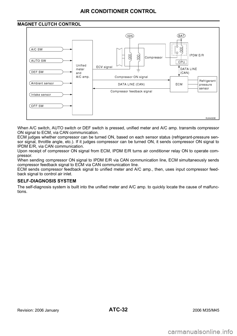
MAGNET CLUTCH CONTROL
When A/C switch, AUTO switch or DEF switch is pressed, unified meter and A/C amp. transmits compressor
ON signal to ECM, via CAN communication.
ECM judges whether compressor can be turned ON, based on each sensor status (refrigerant-pressure sen-
sor signal, throttle angle, etc.). If it judges compressor can be turned ON, it sends compressor ON signal to
IPDM E/R, via CAN communication.
Upon receipt of compressor ON signal from ECM, IPDM E/R turns air conditioner relay ON to operate com-
pressor.
When sending compressor ON signal to IPDM E/R via CAN communication line, ECM simultaneously sends
compressor feedback signal to ECM via CAN communication line.
ECM sends compressor feedback signal to unified meter and A/C amp., then, uses input compressor feed-
back signal to control air inlet.
SELF-DIAGNOSIS SYSTEM
The self-diagnosis system is built into the unified meter and A/C amp. to quickly locate the cause of malfunc-
tions.
RJIA4020E
Page 487 of 5621

ATC-40
TROUBLE DIAGNOSIS
Revision: 2006 January2006 M35/M45
TROUBLE DIAGNOSISPFP:00004
CONSULT-II Function (ECM)NJS000GD
CONSULT-II can display each diagnosis item using the diagnosis test modes shown following.
CONSULT-II BASIC OPERATION
Refer to GI-39, "CONSULT-II Start Procedure" .
DATA MONITOR
Operation Procedure
1. Touch “ENGINE” on “SELECT SYSTEM” screen.
2. Touch “DATA MONITOR” on “SELECT DIAG MODE” screen.
3. Touch either “ALL SIGNALS” or “SELECTION FROM MENU” on “DATA MONITOR” screen.
4. When “SELECTION FROM MENU” is selected, touch items to be monitored. When “ALL SIGNALS” is
selected, all the items will be monitored.
5. Touch “START”.
6. Touch “RECORD” while monitoring, then the status of the monitored item can be recorded. To stop
recording, touch “STOP”.
Display Item List
How to Perform Trouble Diagnosis for Quick and Accurate RepairNJS000GE
WORK FLOW
System part Check item, diagnosis mode Description
ECM Data monitor Displays ECM input data in real time.
All signals Monitors all the items.
Selection from menu Selects and monitors the individual item selected.
Monitor item name
“operation or unit”Contents
IGN ON SW “ON/OFF” Displays “IGN position (ON)/OFF, ACC position (OFF)” status as judged from ignition switch signal.
FAN ON SIG “ON/OFF” Displays “FAN (ON)/FAN (OFF)” status as judged from blower fan motor switch signal.
AIR COND SW “ON/OFF” Displays “COMP (ON)/COMP (OFF)” status as judged from air conditioner switch signal.
REFRIGERANT
PRESSURE SEN-
SOR “V”Displays “Refrigerant pressure sensor for voltage” status as inputted from refrigerant pressure sen-
sor.
*1ATC-64, "Operational Check"
SHA900E