stall INFINITI M35 2006 Factory Service Manual
[x] Cancel search | Manufacturer: INFINITI, Model Year: 2006, Model line: M35, Model: INFINITI M35 2006Pages: 5621, PDF Size: 65.56 MB
Page 4612 of 5621
ACTIVE AFS
LT-185
C
D
E
F
G
H
I
J
L
MA
B
LT
Revision: 2006 January2006 M35/M45
Circuit)" .
AFS Switch Does Not OperateNKS003QU
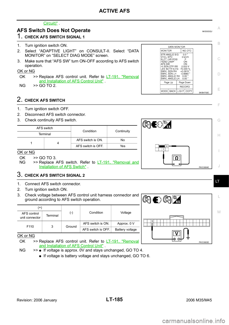
1. CHECK AFS SWITCH SIGNAL 1
1. Turn ignition switch ON.
2. Select “ADAPTIVE LIGHT” on CONSULT-II. Select “DATA
MONITOR” on “SELECT DIAG MODE” screen.
3. Make sure that “AFS SW” turn ON-OFF according to AFS switch
operation.
OK or NG
OK >> Replace AFS control unit. Refer to LT- 1 9 1 , "Removal
and Installation of AFS Control Unit" .
NG >> GO TO 2.
2. CHECK AFS SWITCH
1. Turn ignition switch OFF.
2. Disconnect AFS switch connector.
3. Check continuity AFS switch.
OK or NG
OK >> GO TO 3.
NG >> Replace AFS switch. Refer to LT- 1 9 1 , "
Removal and
Installation of AFS Switch" .
3. CHECK AFS SWITCH SIGNAL 2
1. Connect AFS switch connector.
2. Turn ignition switch ON.
3. Check voltage between AFS control unit harness connector and
ground according to AFS switch operation.
OK or NG
OK >> Replace AFS control unit. Refer to LT- 1 9 1 , "Removal
and Installation of AFS Control Unit" .
NG >>
If voltage is approx. 0V and stays unchanged, GO TO 4.
If voltage is battery voltage and stays unchanged, GO TO 6.
SKIB4793E
AFS switch
Condition Continuity
Te r m i n a l
14AFS switch is ON. No
AFS switch is OFF. Yes
PKIC0684E
(+)
(-) Condition Voltage
AFS control
unit connectorTerminal
F110 3 GroundAFS switch is ON. Approx. 0 V
AFS switch is OFF. Battery voltage
PKIC0683E
Page 4613 of 5621
LT-186
ACTIVE AFS
Revision: 2006 January2006 M35/M45
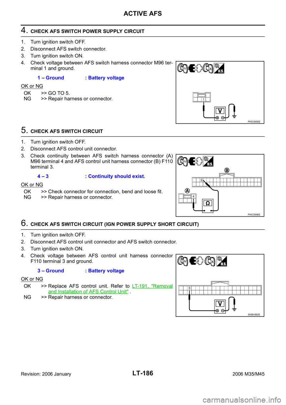
4. CHECK AFS SWITCH POWER SUPPLY CIRCUIT
1. Turn ignition switch OFF.
2. Disconnect AFS switch connector.
3. Turn ignition switch ON.
4. Check voltage between AFS switch harness connector M96 ter-
minal 1 and ground.
OK or NG
OK >> GO TO 5.
NG >> Repair harness or connector.
5. CHECK AFS SWITCH CIRCUIT
1. Turn ignition switch OFF.
2. Disconnect AFS control unit connector.
3. Check continuity between AFS switch harness connector (A)
M96 terminal 4 and AFS control unit harness connector (B) F110
terminal 3.
OK or NG
OK >> Check connector for connection, bend and loose fit.
NG >> Repair harness or connector.
6. CHECK AFS SWITCH CIRCUIT (IGN POWER SUPPLY SHORT CIRCUIT)
1. Turn ignition switch OFF.
2. Disconnect AFS control unit connector and AFS switch connector.
3. Turn ignition switch ON.
4. Check voltage between AFS control unit harness connector
F110 terminal 3 and ground.
OK or NG
OK >> Replace AFS control unit. Refer to LT- 1 9 1 , "Removal
and Installation of AFS Control Unit" .
NG >> Repair harness or connector.1 – Ground : Battery voltage
PKIC0685E
4 – 3 : Continuity should exist.
PKIC0686E
3 – Ground : Battery voltage
SKIB4992E
Page 4614 of 5621
ACTIVE AFS
LT-187
C
D
E
F
G
H
I
J
L
MA
B
LT
Revision: 2006 January2006 M35/M45
Auto Aiming Does Not Operate (Check Aiming Motor System Circuit)NKS003QV
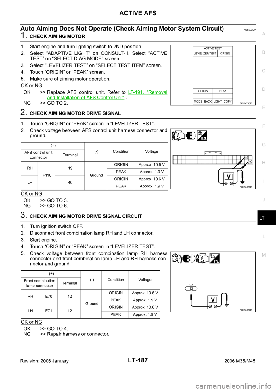
1. CHECK AIMING MOTOR
1. Start engine and turn lighting switch to 2ND position.
2. Select “ADAPTIVE LIGHT” on CONSULT-II. Select “ACTIVE
TEST” on “SELECT DIAG MODE” screen.
3. Select “LEVELIZER TEST” on “SELECT TEST ITEM” screen.
4. Touch “ORIGIN” or “PEAK” screen.
5. Make sure of aiming motor operation.
OK or NG
OK >> Replace AFS control unit. Refer to LT- 1 9 1 , "Removal
and Installation of AFS Control Unit" .
NG >> GO TO 2.
2. CHECK AIMING MOTOR DRIVE SIGNAL
1. Touch “ORIGIN” or “PEAK” screen in “LEVELIZER TEST”.
2. Check voltage between AFS control unit harness connector and
ground.
OK or NG
OK >> GO TO 3.
NG >> GO TO 6.
3. CHECK AIMING MOTOR DRIVE SIGNAL CIRCUIT
1. Turn ignition switch OFF.
2. Disconnect front combination lamp RH and LH connector.
3. Start engine.
4. Touch “ORIGIN” or “PEAK” screen in “LEVELIZER TEST”.
5. Check voltage between front combination lamp RH harness
connector and front combination lamp LH and RH harness con-
nector and ground.
OK or NG
OK >> GO TO 4.
NG >> Repair harness or connector.
SKIB4796E
(+)
(-) Condition Voltage
AFS control unit
connectorTerminal
RH
F11019
GroundORIGIN Approx. 10.6 V
PEAK Approx. 1.9 V
LH 40ORIGIN Approx. 10.6 V
PEAK Approx. 1.9 V
PKIC0687E
(+)
(-) Condition Voltage
Front combination
lamp connectorTerminal
RH E70 12
GroundORIGIN Approx. 10.6 V
PEAK Approx. 1.9 V
LH E71 12ORIGIN Approx. 10.6 V
PEAK Approx. 1.9 V
PKIC0688E
Page 4615 of 5621
LT-188
ACTIVE AFS
Revision: 2006 January2006 M35/M45
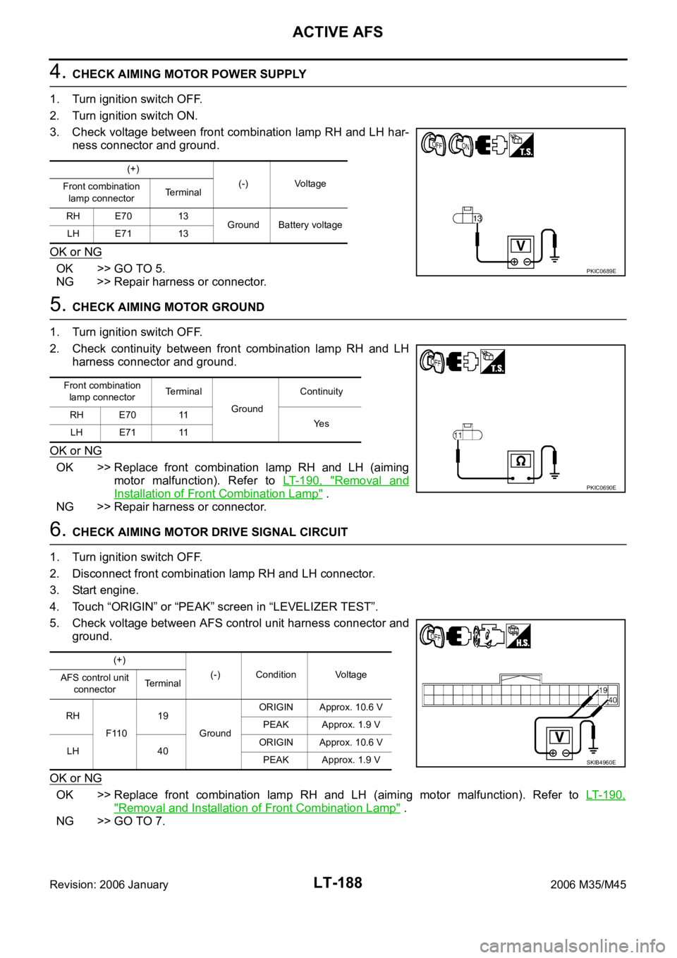
4. CHECK AIMING MOTOR POWER SUPPLY
1. Turn ignition switch OFF.
2. Turn ignition switch ON.
3. Check voltage between front combination lamp RH and LH har-
ness connector and ground.
OK or NG
OK >> GO TO 5.
NG >> Repair harness or connector.
5. CHECK AIMING MOTOR GROUND
1. Turn ignition switch OFF.
2. Check continuity between front combination lamp RH and LH
harness connector and ground.
OK or NG
OK >> Replace front combination lamp RH and LH (aiming
motor malfunction). Refer to LT- 1 9 0 , "
Removal and
Installation of Front Combination Lamp" .
NG >> Repair harness or connector.
6. CHECK AIMING MOTOR DRIVE SIGNAL CIRCUIT
1. Turn ignition switch OFF.
2. Disconnect front combination lamp RH and LH connector.
3. Start engine.
4. Touch “ORIGIN” or “PEAK” screen in “LEVELIZER TEST”.
5. Check voltage between AFS control unit harness connector and
ground.
OK or NG
OK >> Replace front combination lamp RH and LH (aiming motor malfunction). Refer to LT- 1 9 0 ,
"Removal and Installation of Front Combination Lamp" .
NG >> GO TO 7.
(+)
(-) Voltage
Front combination
lamp connectorTerminal
RH E70 13
Ground Battery voltage
LH E71 13
PKIC0689E
Front combination
lamp connectorTerminal
GroundContinuity
RH E70 11
Ye s
LH E71 11
PKIC0690E
(+)
(-) Condition Voltage
AFS control unit
connectorTerminal
RH
F11019
GroundORIGIN Approx. 10.6 V
PEAK Approx. 1.9 V
LH 40ORIGIN Approx. 10.6 V
PEAK Approx. 1.9 V
SKIB4960E
Page 4616 of 5621
ACTIVE AFS
LT-189
C
D
E
F
G
H
I
J
L
MA
B
LT
Revision: 2006 January2006 M35/M45
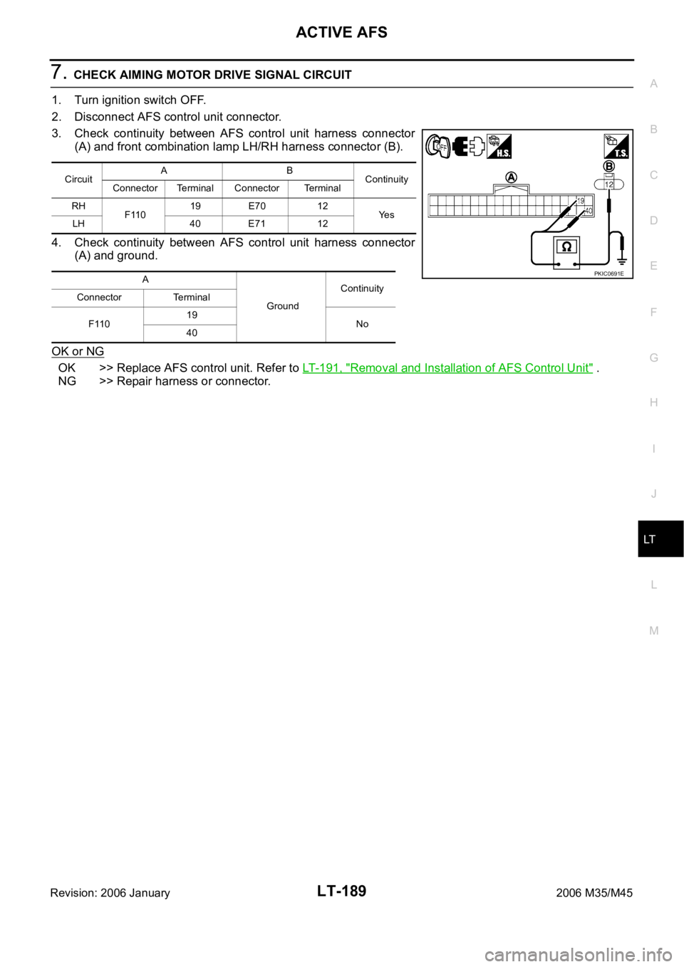
7. CHECK AIMING MOTOR DRIVE SIGNAL CIRCUIT
1. Turn ignition switch OFF.
2. Disconnect AFS control unit connector.
3. Check continuity between AFS control unit harness connector
(A) and front combination lamp LH/RH harness connector (B).
4. Check continuity between AFS control unit harness connector
(A) and ground.
OK or NG
OK >> Replace AFS control unit. Refer to LT-191, "Removal and Installation of AFS Control Unit" .
NG >> Repair harness or connector.
CircuitAB
Continuity
Connector Terminal Connector Terminal
RH
F11019 E70 12
Ye s
LH 40 E71 12
A
GroundContinuity
Connector Terminal
F11019
No
40
PKIC0691E
Page 4617 of 5621

LT-190
ACTIVE AFS
Revision: 2006 January2006 M35/M45
AFS OFF Indicator Does Not OperateNKS003QW
1. CHECK DIAGNOSIS RESULT (AFS CONTROL UNIT)
Select “ADAPTIVE LIGHT” on CONSULT-II. Select “SELF-DIAG
RESULTS” on “SELECT DIAG MODE” screen.
Is DTC detected?
YES >> Refer to LT- 1 5 4 , "SELF-DIAG RESULTS" .
NO >> GO TO 2.
2. CHECK DIAGNOSIS RESULT (UNIFIED METER AND A/C AMP.)
Select “METER A/C AMP” on CONSULT-II. Select “SELF-DIAG
RESULTS” on “SELECT DIAG MODE” screen.
Is DTC detected?
YES >> Refer to DI-32, "SELF-DIAG RESULTS" in DI section.
NO >> GO TO 3.
3. CHECK AFS OFF INDICATOR SIGNAL (UNIFIED METER AND A/C AMP.)
Check “AFS OFF IND” in “Data Monitor” according to AFS switch
operation.
OK or NG
OK >> Replace combination meter.
NG >> Replace unified meter and A/C amp.
Removal and Installation of Steering Angle SensorNKS003QX
Refer to BRC-63, "STEERING ANGLE SENSOR" .
Removal and Installation of Front Combination LampNKS003QY
Refer to LT-41, "Removal and Installation" .
PKIA6866E
PKIA6866E
Condition “AFS OFF IND”
AFS switch is OFF. ON
AFS switch is ON. OFF
SKIB4971E
Page 4618 of 5621

ACTIVE AFS
LT-191
C
D
E
F
G
H
I
J
L
MA
B
LT
Revision: 2006 January2006 M35/M45
Removal and Installation of AFS Control UnitNKS003QZ
REMOVAL
1. Remove dash side finisher RH. Refer to EI-37, "BODY SIDE TRIM" in EI section.
2. Remove screw (A).
3. Disconnect AFS control unit connector.
4. Remove AFS control unit (1).
INSTALLATION
Installation is the reverse order of removal.
Removal and Installation of AFS SwitchNKS003R0
REMOVAL
1. Remove instrument lower driver panel. Refer to IP-10, "INSTRUMENT PANEL ASSEMBLY" in IP section.
2. Press AFS switch fixing pawls (A) and remove unit (1) from
instrument lower driver panel.
INSTALLATION
Installation is the reverse order of removal.
SKIB4766E
SKIB4768E
Page 4619 of 5621

LT-192
ACTIVE AFS
Revision: 2006 January2006 M35/M45
Removal and Installation of Height SensorNKS003R1
REMOVAL
1. Disconnect height sensor connector.
2. Remove height sensor link bracket mounting nuts (1). (rear stabilizer side)
CAUTION:
Never remove from the installation nut of height sensor link bracket (height sensor link side).
3. Remove bolts (2), and remove height sensor.
: Nꞏm (kg-m, ft-lb)
INSTALLATION
Installation is the reverse order of removal.
CAUTION:
Tighten the bracket while pushing onto rear stabilizer when installing the installation nut of height
sensor link bracket (stabilizer side).
NOTE:
Adjust levelizer when replacing height sensor. For details, refer to LT- 1 5 3 , "
WORK SUPPORT (LEVELIZER
ADJUSTMENT)" .
SKIB4211E
Page 4629 of 5621

LT-202
FRONT FOG LAMP
Revision: 2006 January2006 M35/M45
Terminals and Reference Values for IPDM E/RNKS003R9
How to Perform Trouble DiagnosesNKS003RA
1. Confirm the symptom or customer complaint.
2. Understand operation description and function description. Refer to LT- 1 9 3 , "
System Description" .
3. Perform the Preliminary Check. Refer to LT-202, "
Preliminary Check" .
4. Check symptom and repair or replace the cause of malfunction.
5. Does the front fog lamp operate normally? If YES, GO TO 6. If NO, GO TO 4.
6. INSPECTION END
Preliminary CheckNKS003RB
CHECK POWER SUPPLY AND GROUND CIRCUIT
1. CHECK FUSE
Check for blown fuses.
Refer to LT-197, "Wiring Diagram — F/FOG —" .
OK or NG
OK >> GO TO 2.
NG >> If fuse or fusible link is blown, be sure to eliminate cause of malfunction before installing new fuse
or fusible link. Refer to PG-3, "
POWER SUPPLY ROUTING CIRCUIT" .
Terminal
No.Wire
colorSignal nameMeasuring condition
Reference value
Ignition
switchOperation or condition
36 L/Y Front fog lamp (LH) ONLighting switch must be in
the 2ND position or AUTO
position (headlamp is ON)Front fog lamp switch: OFF Approx. 0V
Front fog lamp switch: ON Battery voltage
37 W/R Front fog lamp (RH) ONLighting switch must be in
the 2ND position or AUTO
position (headlamp is ON)Front fog lamp switch: OFF Approx. 0V
Front fog lamp switch: ON Battery voltage
38 B Ground ON — Approx. 0V
49 L CAN
H — — —
50 P CAN
L — — —
51 B Ground ON — Approx. 0V
Unit Power source Fuse and fusible link No.
BCMBatteryF
21
Ignition switch ON or START position 1
Ignition switch ACC or ON position 6
IPDM E/R Battery71
88
78
Page 4631 of 5621
LT-204
FRONT FOG LAMP
Revision: 2006 January2006 M35/M45
Front Fog Lamps Do Not Illuminate (Both Sides)NKS003RE
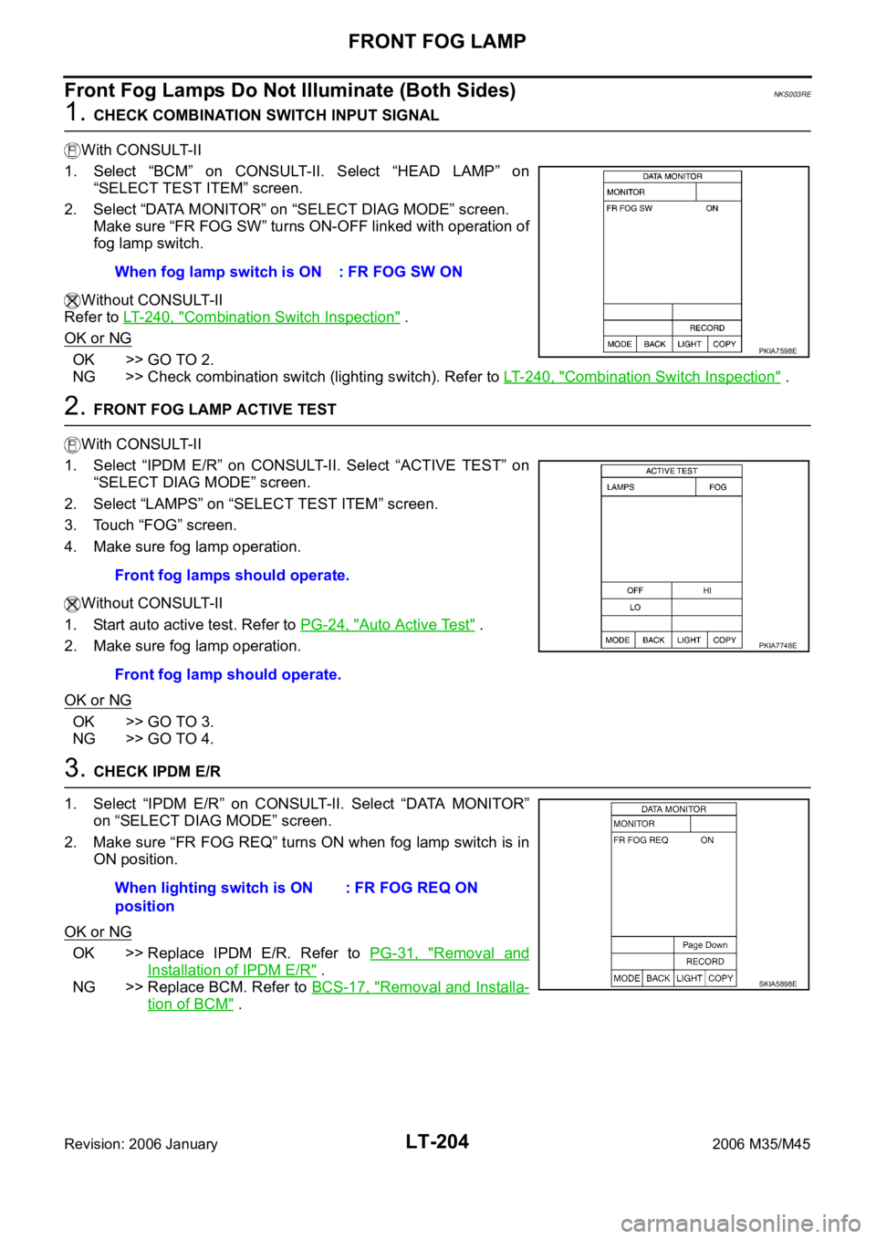
1. CHECK COMBINATION SWITCH INPUT SIGNAL
With CONSULT-II
1. Select “BCM” on CONSULT-II. Select “HEAD LAMP” on
“SELECT TEST ITEM” screen.
2. Select “DATA MONITOR” on “SELECT DIAG MODE” screen.
Make sure “FR FOG SW” turns ON-OFF linked with operation of
fog lamp switch.
Without CONSULT-II
Refer to LT- 2 4 0 , "
Combination Switch Inspection" .
OK or NG
OK >> GO TO 2.
NG >> Check combination switch (lighting switch). Refer to LT-240, "
Combination Switch Inspection" .
2. FRONT FOG LAMP ACTIVE TEST
With CONSULT-II
1. Select “IPDM E/R” on CONSULT-II. Select “ACTIVE TEST” on
“SELECT DIAG MODE” screen.
2. Select “LAMPS” on “SELECT TEST ITEM” screen.
3. Touch “FOG” screen.
4. Make sure fog lamp operation.
Without CONSULT-II
1. Start auto active test. Refer to PG-24, "
Auto Active Test" .
2. Make sure fog lamp operation.
OK or NG
OK >> GO TO 3.
NG >> GO TO 4.
3. CHECK IPDM E/R
1. Select “IPDM E/R” on CONSULT-II. Select “DATA MONITOR”
on “SELECT DIAG MODE” screen.
2. Make sure “FR FOG REQ” turns ON when fog lamp switch is in
ON position.
OK or NG
OK >> Replace IPDM E/R. Refer to PG-31, "Removal and
Installation of IPDM E/R" .
NG >> Replace BCM. Refer to BCS-17, "
Removal and Installa-
tion of BCM" . When fog lamp switch is ON : FR FOG SW ON
PKIA7598E
Front fog lamps should operate.
Front fog lamp should operate.
PKIA7748E
When lighting switch is ON
position: FR FOG REQ ON
SKIA5898E