stall INFINITI M35 2006 Factory Service Manual
[x] Cancel search | Manufacturer: INFINITI, Model Year: 2006, Model line: M35, Model: INFINITI M35 2006Pages: 5621, PDF Size: 65.56 MB
Page 4633 of 5621

LT-206
FRONT FOG LAMP
Revision: 2006 January2006 M35/M45
6. CHECK FRONT FOG LAMP CIRCUIT
1. Turn ignition switch OFF.
2. Disconnect IPDM E/R connector.
3. Check continuity between IPDM E/R harness connector (A) and
front fog lamp (RH and LH) harness connector (B).
4. Check harness continuity between IPDM E/R harness connector
(A) terminal and ground.
OK or NG
OK >> Replace IPDM E/R. Refer to PG-31, "Removal and Installation of IPDM E/R" .
NG >> Repair harness or connector.
CircuitAB
Continuity
Connector Terminal Connector Terminal
RH
E837 E45 1
Ye s
LH 36 E60 1
A
GroundContinuity
Connector Terminal
RH
E837
No
LH 38
SKIB4815E
Page 4635 of 5621

LT-208
FRONT FOG LAMP
Revision: 2006 January2006 M35/M45
4. CHECK FOG LAMP CIRCUIT
1. Turn ignition switch OFF.
2. Disconnect IPDM E/R connector.
3. Check continuity between IPDM E/R harness connector (A) and
front fog lamp RH or LH harness connector (B).
4. Check harness continuity between IPDM E/R harness connector
(A) and ground.
OK or NG
OK >> Replace IPDM E/R. Refer to PG-31, "Removal and Installation of IPDM E/R" .
NG >> Repair harness or connector.
Front Fog Lamps Do Not Turn OFFNKS003RG
1. CHECK FRONT FOG LAMP TURN OFF
Make sure that lighting switch is OFF. And make sure front fog lamp turns off when ignition switch is turned
OFF.
OK or NG
OK >> GO TO 3.
NG >> GO TO 2.
2. CHECK COMBINATION SWITCH INPUT SIGNAL
Select “BCM” on CONSULT-II. With “HEAD LAMP” data monitor,
make sure “FR FOG SW” turns ON-OFF linked with operation of fog
lamp switch.
OK or NG
OK >> Replace IPDM E/R. Refer to PG-31, "Removal and
Installation of IPDM E/R" .
NG >> Check combination switch (lighting switch). Refer to LT-
240, "Combination Switch Inspection" .
CircuitAB
Continuity
Connector Terminal Connector Terminal
RH
E836 E60 1
Ye s
LH 37 E45 1
A
GroundContinuity
Connector Terminal
RH
E836
No
LH 37
SKIB4815E
When fog lamp switch is
OFF position: FR FOG SW OFF
PKIB9378E
Page 4636 of 5621

FRONT FOG LAMP
LT-209
C
D
E
F
G
H
I
J
L
MA
B
LT
Revision: 2006 January2006 M35/M45
3. CHECK CAN COMMUNICATIONS BETWEEN BCM AND IPDM E/R
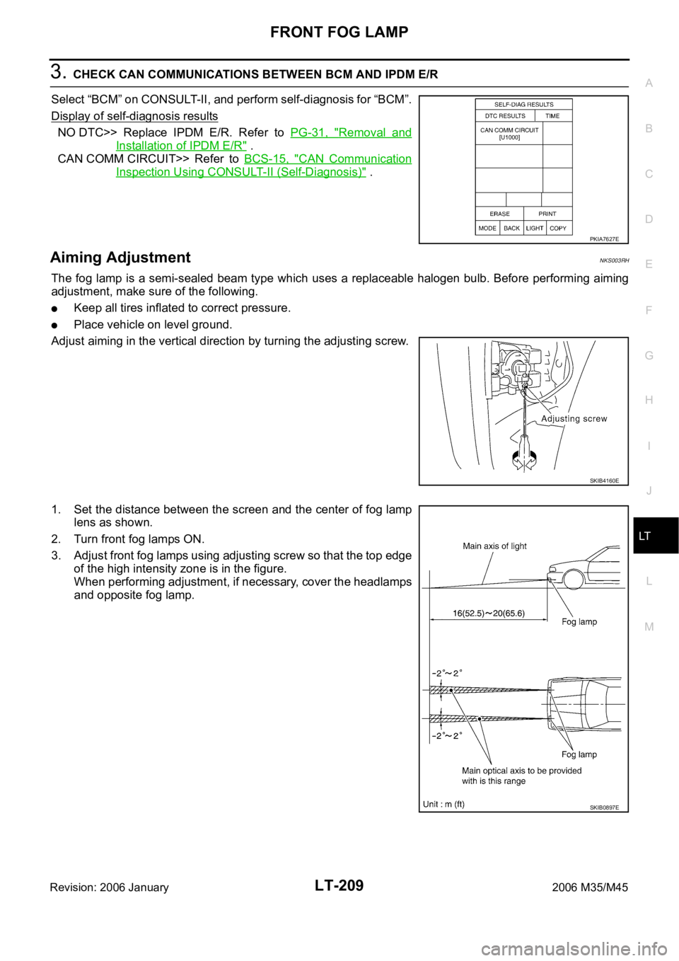
Select “BCM” on CONSULT-II, and perform self-diagnosis for “BCM”.
Display of self-diagnosis results
NO DTC>> Replace IPDM E/R. Refer to PG-31, "Removal and
Installation of IPDM E/R" .
CAN COMM CIRCUIT>> Refer to BCS-15, "
CAN Communication
Inspection Using CONSULT-II (Self-Diagnosis)" .
Aiming AdjustmentNKS003RH
The fog lamp is a semi-sealed beam type which uses a replaceable halogen bulb. Before performing aiming
adjustment, make sure of the following.
Keep all tires inflated to correct pressure.
Place vehicle on level ground.
Adjust aiming in the vertical direction by turning the adjusting screw.
1. Set the distance between the screen and the center of fog lamp
lens as shown.
2. Turn front fog lamps ON.
3. Adjust front fog lamps using adjusting screw so that the top edge
of the high intensity zone is in the figure.
When performing adjustment, if necessary, cover the headlamps
and opposite fog lamp.
PKIA7627E
SKIB4160E
SKIB0897E
Page 4637 of 5621

LT-210
FRONT FOG LAMP
Revision: 2006 January2006 M35/M45
Bulb ReplacementNKS003RI
1. Turn lighting switch OFF.
2. Remove fender protector (front). Refer to EI-20, "
FENDER PROTECTOR" .
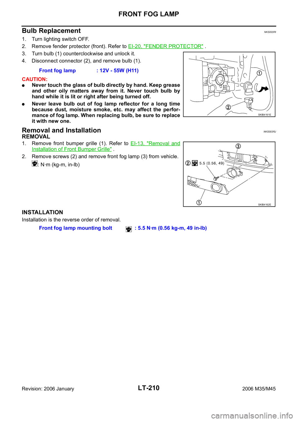
3. Turn bulb (1) counterclockwise and unlock it.
4. Disconnect connector (2), and remove bulb (1).
CAUTION:
Never touch the glass of bulb directly by hand. Keep grease
and other oily matters away from it. Never touch bulb by
hand while it is lit or right after being turned off.
Never leave bulb out of fog lamp reflector for a long time
because dust, moisture smoke, etc. may affect the perfor-
mance of fog lamp. When replacing bulb, be sure to replace
it with new one.
Removal and InstallationNKS003RJ
REMOVAL
1. Remove front bumper grille (1). Refer to EI-13, "Removal and
Installation of Front Bumper Grille" .
2. Remove screws (2) and remove front fog lamp (3) from vehicle.
: Nꞏm (kg-m, in-lb)
INSTALLATION
Installation is the reverse order of removal.Front fog lamp : 12V - 55W (H11)
SKIB4161E
SKIB4162E
Front fog lamp mounting bolt : 5.5 Nꞏm (0.56 kg-m, 49 in-lb)
Page 4648 of 5621

TURN SIGNAL AND HAZARD WARNING LAMPS
LT-221
C
D
E
F
G
H
I
J
L
MA
B
LT
Revision: 2006 January2006 M35/M45
Preliminary CheckNKS003RS
CHECK POWER SUPPLY AND GROUND CIRCUIT
1. CHECK FUSE
Check for blown fuses.
Refer to LT-215, "Wiring Diagram — TURN —" .
OK or NG
OK >> GO TO 2.
NG >> If fuse or fusible link is blown, be sure to eliminate cause of malfunction before installing new fuse
or fusible link. Refer to PG-3, "
POWER SUPPLY ROUTING CIRCUIT" .
2. CHECK POWER SUPPLY CIRCUIT
1. Turn ignition switch OFF.
2. Disconnect BCM connector.
3. Check voltage between BCM harness connector and ground.
OK or NG
OK >> GO TO 3.
NG >> Check harness for open or short between BCM and
fuse.
Unit Power source Fuse and fusible link No.
BCMBatteryF
21
Ignition switch ON or START position 1
Combination meterBattery 21
Ignition switch ON or START position 14
Unified meter and A/C amp.Battery 19
Ignition switch ON or START position 12
Terminal Ignition switch position
(+)
(-) OFF ACC ON
BCM
connectorTerminal
A38
GroundApprox. 0V Approx. 0VBattery
voltage
B42Battery
voltageBattery
voltageBattery
voltage
55Battery
voltageBattery
voltageBattery
voltage
SKIB5059E
Page 4652 of 5621

TURN SIGNAL AND HAZARD WARNING LAMPS
LT-225
C
D
E
F
G
H
I
J
L
MA
B
LT
Revision: 2006 January2006 M35/M45
Turn Signal Lamp Does Not OperateNKS003RU
1. CHECK BULB
Check bulb standard of each turn signal lamp is correct.
OK or NG
OK >> GO TO 2.
NG >> Replace turn signal lamp bulb.
2. CHECK COMBINATION SWITCH INPUT SIGNAL
With CONSULT-II
1. Select “BCM” on CONSULT-II. Select “FLASHER” on “SELECT
TEST ITEM” screen.
2. Select “DATA MONITOR” on “SELECT DIAG MODE” screen.
Make sure “TURN SIGNAL R” and “TURN SIGNAL L” turns ON-
OFF linked with operation of lighting switch.
Without CONSULT-II
Refer to LT-240, "
Combination Switch Inspection" .
OK or NG
OK >> GO TO 3.
NG >> Check combination switch (lighting switch). Refer to LT- 2 4 0 , "
Combination Switch Inspection" .
3. ACTIVE TEST
With CONSULT-II
1. Select “BCM” on CONSULT-II. Select “FLASHER” on “SELECT
TEST ITEM” screen.
2. Select “ACTIVE TEST” on “SELECT DIAG MODE” screen.
Select “FLASHER” on “SELECT TEST ITEM” screen.
3. Make sure operation of turn signal lamps.
Without CONSULT-II
GO TO 4.
OK or NG
OK >> Replace BCM. Refer to BCS-17, "Removal and Installa-
tion of BCM" .
NG >> GO TO 4.When lighting switch is
TURN RH position: TURN SIGNAL R ON
When lighting switch is
TURN LH position: TURN SIGNAL L ON
PKIA7600E
Turn signal lamp should operate.
SKIA6190E
Page 4653 of 5621

LT-226
TURN SIGNAL AND HAZARD WARNING LAMPS
Revision: 2006 January2006 M35/M45
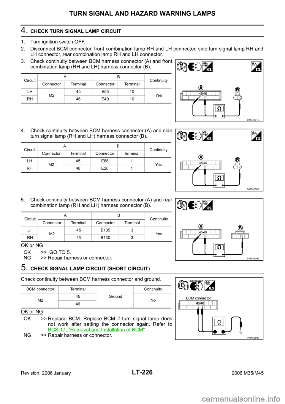
4. CHECK TURN SIGNAL LAMP CIRCUIT
1. Turn ignition switch OFF.
2. Disconnect BCM connector, front combination lamp RH and LH connector, side turn signal lamp RH and
LH connector, rear combination lamp RH and LH connector.
3. Check continuity between BCM harness connector (A) and front
combination lamp (RH and LH) harness connector (B).
4. Check continuity between BCM harness connector (A) and side
turn signal lamp (RH and LH) harness connector (B).
5. Check continuity between BCM harness connector (A) and rear
combination lamp (RH and LH) harness connector (B).
OK or NG
OK >> GO TO 5.
NG >> Repair harness or connector.
5. CHECK SIGNAL LAMP CIRCUIT (SHORT CIRCUIT)
Check continuity between BCM harness connector and ground.
OK or NG
OK >> Replace BCM. Replace BCM if turn signal lamp does
not work after setting the connector again. Refer to
BCS-17, "
Removal and Installation of BCM" .
NG >> Repair harness or connector.
CircuitAB
Continuity
Connector Terminal Connector Terminal
LH
M245 E55 10
Ye s
RH 46 E49 10
SKIB4807E
CircuitAB
Continuity
Connector Terminal Connector Terminal
LH
M245 E68 1
Ye s
RH 46 E28 1
SKIB4808E
CircuitAB
Continuity
Connector Terminal Connector Terminal
LH
M245 B135 3
Ye s
RH 46 B130 3
SKIB4809E
BCM connector Terminal
GroundContinuity
M245
No
46
PKIA6289E
Page 4654 of 5621

TURN SIGNAL AND HAZARD WARNING LAMPS
LT-227
C
D
E
F
G
H
I
J
L
MA
B
LT
Revision: 2006 January2006 M35/M45
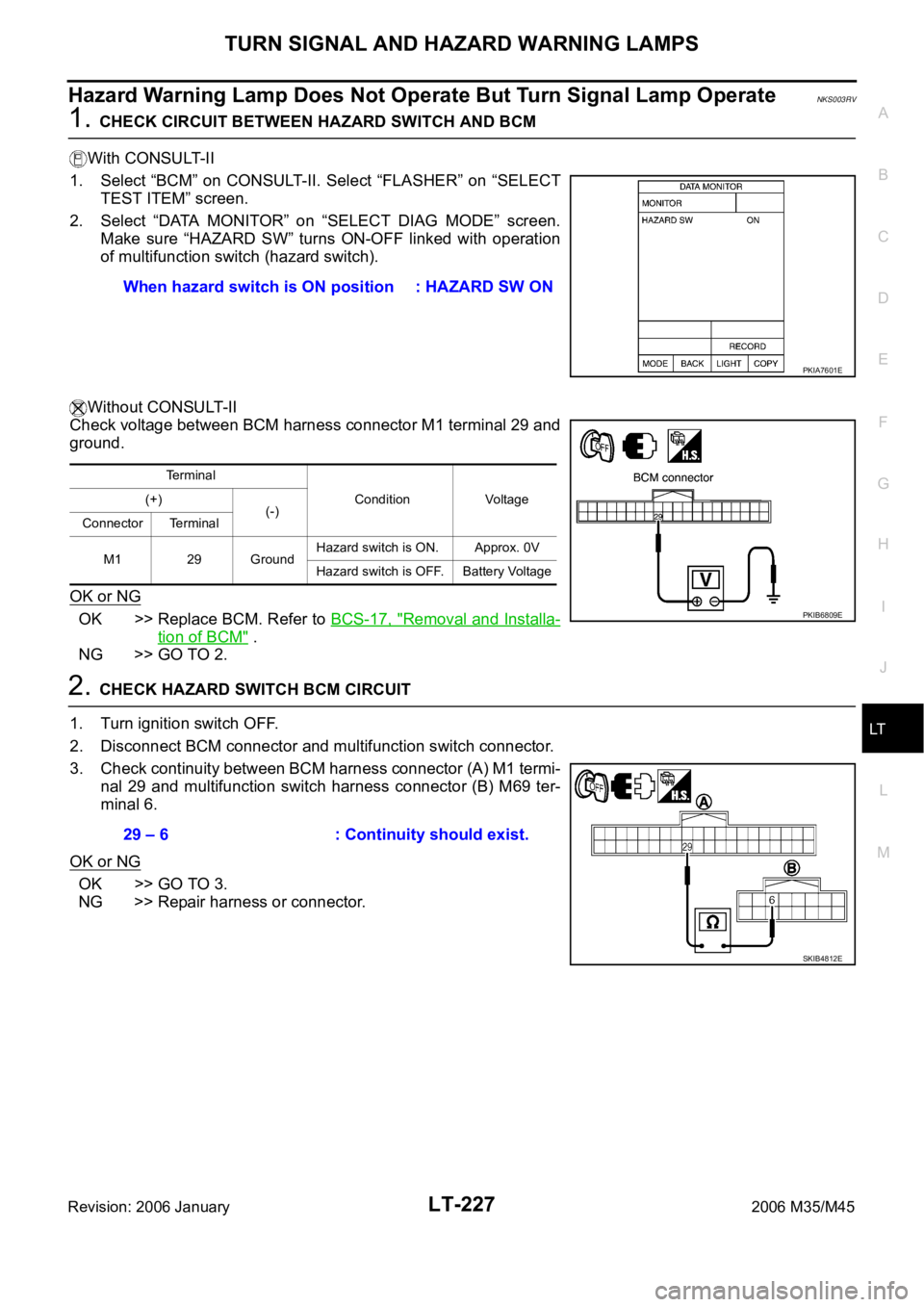
Hazard Warning Lamp Does Not Operate But Turn Signal Lamp OperateNKS003RV
1. CHECK CIRCUIT BETWEEN HAZARD SWITCH AND BCM
With CONSULT-II
1. Select “BCM” on CONSULT-II. Select “FLASHER” on “SELECT
TEST ITEM” screen.
2. Select “DATA MONITOR” on “SELECT DIAG MODE” screen.
Make sure “HAZARD SW” turns ON-OFF linked with operation
of multifunction switch (hazard switch).
Without CONSULT-II
Check voltage between BCM harness connector M1 terminal 29 and
ground.
OK or NG
OK >> Replace BCM. Refer to BCS-17, "Removal and Installa-
tion of BCM" .
NG >> GO TO 2.
2. CHECK HAZARD SWITCH BCM CIRCUIT
1. Turn ignition switch OFF.
2. Disconnect BCM connector and multifunction switch connector.
3. Check continuity between BCM harness connector (A) M1 termi-
nal 29 and multifunction switch harness connector (B) M69 ter-
minal 6.
OK or NG
OK >> GO TO 3.
NG >> Repair harness or connector.When hazard switch is ON position : HAZARD SW ON
PKIA7601E
Terminal
Condition Voltage (+)
(-)
Connector Terminal
M1 29 GroundHazard switch is ON. Approx. 0V
Hazard switch is OFF. Battery Voltage
PKIB6809E
29 – 6 : Continuity should exist.
SKIB4812E
Page 4655 of 5621

LT-228
TURN SIGNAL AND HAZARD WARNING LAMPS
Revision: 2006 January2006 M35/M45
3. CHECK HAZARD SWITCH GROUND CIRCUIT
Check continuity between multifunction switch harness connector
terminal 14 and ground.
OK or NG
OK >> GO TO 4.
NG >> Repair harness or connector.
4. CHECK HAZARD SWITCH
Check continuity multifunction switch (hazard switch).
OK or NG
OK >> Replace BCM. Replace BCM if turn signal lamp does
not work after setting the connector again. Refer to
BCS-17, "
Removal and Installation of BCM" .
NG >> Replace multifunction switch. Refer to AV- 2 9 2 , "
Multifunction Switch" .
Turn Signal Indicator Lamp Does Not OperateNKS003RW
1. CHECK BULB
Check bulb of turn signal indicator lamp in combination meter.
OK or NG
OK >> Replace combination meter.
NG >> Replace indicator bulb.14 – Ground : Continuity should exist.
SKIB4813E
Multifunction switch
(Hazard switch)
Condition Continuity
Terminal
614Hazard switch is ON. Yes
Hazard switch is OFF. No
SKIB4814E
Page 4656 of 5621

TURN SIGNAL AND HAZARD WARNING LAMPS
LT-229
C
D
E
F
G
H
I
J
L
MA
B
LT
Revision: 2006 January2006 M35/M45
Bulb Replacement/Removal and Installation of Side Turn Signal LampNKS003RX
: Vehicle front
REMOVAL
1. While pressing the side turn signal lamp (1) to direction A (Ve h i -
cle front), pull direction B of it and remove.
2. Disconnect side turn signal lamp connector.
CAUTION:
Support side turn signal lamp harness with tape so that it
won't fall into the front fender.
Fix the pawl side of side turn signal lamp housing back at
first. Then install side turn signal lamp while pushing
resin clip side.
3. Turn bulb socket (1) counterclockwise and unlock it.
4. Remove bulb (2).
INSTALLATION
Installation is the reverse order of removal.
Bulb Replacement (Front Turn Signal Lamp)NKS003RY
Refer to LT- 3 9 , "Bulb Replacement" in “HEADLAMP -CONVENTIONAL TYPE-”.
Refer to LT- 7 5 , "
Bulb Replacement" in “HEADLAMP -XENON TYPE-”.
Bulb Replacement (Rear Turn Signal Lamp)NKS003RZ
Refer to LT-266, "Bulb Replacement" .
Removal and Installation of Front Turn Signal LampNKS003S0
Refer to LT- 4 1 , "Removal and Installation" .
Removal and Installation of Rear Turn Signal Lamp NKS003S1
Refer to LT-266, "Removal and Installation" .
SKIB4184E
Side turn signal lamp : 12V - 5W
SKIB4185E