tire pressure INFINITI M35 2006 Factory Service Manual
[x] Cancel search | Manufacturer: INFINITI, Model Year: 2006, Model line: M35, Model: INFINITI M35 2006Pages: 5621, PDF Size: 65.56 MB
Page 4413 of 5621
![INFINITI M35 2006 Factory Service Manual LAN-744
[CAN]
CAN SYSTEM (TYPE 15)
Revision: 2006 January2006 M35/M45
2. CHECK HARNESS FOR OPEN CIRCUIT
1. Disconnect LDW camera unit connector.
2. Check resistance between LDW camera unit harness con INFINITI M35 2006 Factory Service Manual LAN-744
[CAN]
CAN SYSTEM (TYPE 15)
Revision: 2006 January2006 M35/M45
2. CHECK HARNESS FOR OPEN CIRCUIT
1. Disconnect LDW camera unit connector.
2. Check resistance between LDW camera unit harness con](/img/42/57023/w960_57023-4412.png)
LAN-744
[CAN]
CAN SYSTEM (TYPE 15)
Revision: 2006 January2006 M35/M45
2. CHECK HARNESS FOR OPEN CIRCUIT
1. Disconnect LDW camera unit connector.
2. Check resistance between LDW camera unit harness connector
terminals.
OK or NG
OK >> Replace LDW camera unit.
NG >> Repair harness between LDW camera unit and harness
connector M61.
Low Tire Pressure Warning Control Unit Circuit InspectionNKS0047S
1. CHECK CONNECTOR
1. Turn ignition switch OFF.
2. Disconnect the battery cable from the negative terminal.
3. Check terminals and connector of low tire pressure warning control unit for damage, bend and loose con-
nection (control unit side and harness side).
OK or NG
OK >> GO TO 2.
NG >> Repair terminal or connector.
2. CHECK HARNESS FOR OPEN CIRCUIT
1. Disconnect low tire pressure warning control unit connector.
2. Check resistance between low tire pressure warning control unit
harness connector terminals.
OK or NG
OK >> Replace low tire pressure warning control unit.
NG >> Repair harness between low tire pressure warning con-
trol unit and data link connector.
Steering Angle Sensor Circuit InspectionNKS0047T
1. CHECK CONNECTOR
1. Turn ignition switch OFF.
2. Disconnect the battery cable from the negative terminal.
3. Check terminals and connector of steering angle sensor for damage, bend and loose connection (sensor
side and harness side).
OK or NG
OK >> GO TO 2.
NG >> Repair terminal or connector.
LDW camera unit
connectorTerminalResistance
(Approx.)
M182 10 5 54 – 66
SKIB2333E
Low tire pressure
warning control
unit connectorTerminalResistance
(Approx.)
M19 15 16 54 – 66
PKIC0285E
Page 4419 of 5621
![INFINITI M35 2006 Factory Service Manual LAN-750
[CAN]
CAN SYSTEM (TYPE 15)
Revision: 2006 January2006 M35/M45
CAN Communication Circuit InspectionNKS00483
1. CHECK CONNECTOR
1. Turn ignition switch OFF.
2. Disconnect the battery cable from INFINITI M35 2006 Factory Service Manual LAN-750
[CAN]
CAN SYSTEM (TYPE 15)
Revision: 2006 January2006 M35/M45
CAN Communication Circuit InspectionNKS00483
1. CHECK CONNECTOR
1. Turn ignition switch OFF.
2. Disconnect the battery cable from](/img/42/57023/w960_57023-4418.png)
LAN-750
[CAN]
CAN SYSTEM (TYPE 15)
Revision: 2006 January2006 M35/M45
CAN Communication Circuit InspectionNKS00483
1. CHECK CONNECTOR
1. Turn ignition switch OFF.
2. Disconnect the battery cable from the negative terminal.
3. Check following terminals and connectors for damage, bend and loose connection (control module side,
control unit side, unit side, sensor side, meter side and harness side).
–ECM
–A/T assembly
–AWD control unit
–AFS control unit
–BCM
–LDW camera unit
–Low tire pressure warning control unit
–Steering angle sensor
–Intelligent Key unit
–Unified meter and A/C amp.
–NAVI control unit
–Pre-crash seat belt control unit
–Driver seat control unit
–ABS actuator and electric unit (control unit)
–ICC sensor integrated unit
–IPDM E/R
–Between ECM and A/T assembly
–Between ECM and AWD control unit
–Between ECM and AFS control unit
–Between ECM and NAVI control unit
–Between ECM and driver seat control unit
–Between ECM and IPDM E/R
OK or NG
OK >> GO TO 2.
NG >> Repair terminal or connector.
Page 4422 of 5621
![INFINITI M35 2006 Factory Service Manual CAN SYSTEM (TYPE 15)
LAN-753
[CAN]
C
D
E
F
G
H
I
J
L
MA
B
LAN
Revision: 2006 January2006 M35/M45
9. CHECK HARNESS FOR SHORT CIRCUIT
Check continuity between AFS control unit harness connector termi-
n INFINITI M35 2006 Factory Service Manual CAN SYSTEM (TYPE 15)
LAN-753
[CAN]
C
D
E
F
G
H
I
J
L
MA
B
LAN
Revision: 2006 January2006 M35/M45
9. CHECK HARNESS FOR SHORT CIRCUIT
Check continuity between AFS control unit harness connector termi-
n](/img/42/57023/w960_57023-4421.png)
CAN SYSTEM (TYPE 15)
LAN-753
[CAN]
C
D
E
F
G
H
I
J
L
MA
B
LAN
Revision: 2006 January2006 M35/M45
9. CHECK HARNESS FOR SHORT CIRCUIT
Check continuity between AFS control unit harness connector termi-
nals and ground.
OK or NG
OK >> GO TO 10.
NG >> Replace harness between AFS control unit and harness
connector F102.
10. CHECK HARNESS FOR SHORT CIRCUIT
1. Disconnect following connectors.
–Low tire pressure warning control unit connector
–Steering angle sensor connector
–Intelligent Key unit connector
–Unified meter and A/C amp. connector
–Harness connector M53
–Harness connector M13
2. Check continuity between data link connector terminals.
OK or NG
OK >> GO TO 11.
NG >> Check the following harnesses. If any harness is dam-
aged, repair the harness.
Harness between data link connector and harness
connector M62
Harness between data link connector and low tire pressure warning control unit
Harness between data link connector and steering angle sensor
Harness between data link connector and Intelligent Key unit
Harness between data link connector and unified meter and A/C amp.
Harness between data link connector and harness connector M53
Harness between data link connector and harness connector M13
AFS control unit
connectorTerminal
GroundContinuity
F11030 No
7No
PKIC0298E
Data link
connectorTerminal Continuity
M60 6 14 No
PKIA9865E
Page 4423 of 5621
![INFINITI M35 2006 Factory Service Manual LAN-754
[CAN]
CAN SYSTEM (TYPE 15)
Revision: 2006 January2006 M35/M45
11 . CHECK HARNESS FOR SHORT CIRCUIT
Check continuity between data link connector terminals and ground.
OK or NG
OK >> GO TO 12.
INFINITI M35 2006 Factory Service Manual LAN-754
[CAN]
CAN SYSTEM (TYPE 15)
Revision: 2006 January2006 M35/M45
11 . CHECK HARNESS FOR SHORT CIRCUIT
Check continuity between data link connector terminals and ground.
OK or NG
OK >> GO TO 12.](/img/42/57023/w960_57023-4422.png)
LAN-754
[CAN]
CAN SYSTEM (TYPE 15)
Revision: 2006 January2006 M35/M45
11 . CHECK HARNESS FOR SHORT CIRCUIT
Check continuity between data link connector terminals and ground.
OK or NG
OK >> GO TO 12.
NG >> Check the following harnesses. If any harness is dam-
aged, repair the harness.
Harness between data link connector and harness
connector M62
Harness between data link connector and low tire pressure warning control unit
Harness between data link connector and steering angle sensor
Harness between data link connector and Intelligent Key unit
Harness between data link connector and unified meter and A/C amp.
Harness between data link connector and harness connector M53
Harness between data link connector and harness connector M13
12. CHECK HARNESS FOR SHORT CIRCUIT
1. Disconnect NAVI control unit connector.
2. Check continuity between NAVI control unit harness connector
terminals.
OK or NG
OK >> GO TO 13.
NG >> Repair harness between NAVI control unit and harness
connector M216.
13. CHECK HARNESS FOR SHORT CIRCUIT
Check continuity between NAVI control unit harness connector ter-
minals and ground.
OK or NG
OK >> GO TO 14.
NG >> Repair harness between NAVI control unit and harness
connector M216.
Data link
connectorTerminal
GroundContinuity
M606No
14 No
PKIA9872E
NAVI control unit
connectorTerminal Continuity
M210 71 72 No
PKIC0288E
NAVI control unit
connectorTerminal
GroundContinuity
M21071 No
72 No
PKIC0291E
Page 4427 of 5621
![INFINITI M35 2006 Factory Service Manual LAN-758
[CAN]
CAN SYSTEM (TYPE 15)
Revision: 2006 January2006 M35/M45
22. CHECK UNIT REPRODUCIBILITY
Performs the following procedure for each unit, and then perform reproducibility test.
1. Turn igni INFINITI M35 2006 Factory Service Manual LAN-758
[CAN]
CAN SYSTEM (TYPE 15)
Revision: 2006 January2006 M35/M45
22. CHECK UNIT REPRODUCIBILITY
Performs the following procedure for each unit, and then perform reproducibility test.
1. Turn igni](/img/42/57023/w960_57023-4426.png)
LAN-758
[CAN]
CAN SYSTEM (TYPE 15)
Revision: 2006 January2006 M35/M45
22. CHECK UNIT REPRODUCIBILITY
Performs the following procedure for each unit, and then perform reproducibility test.
1. Turn ignition switch OFF.
2. Disconnect the battery cable from the negative terminal.
3. Disconnect the unit connector.
4. Connect the battery cable to the negative terminal.
5. Make sure that the symptom filled in the “Symptom” of the check sheet is reproduced. (Do not confuse it
with the symptom related to removed unit.)
6. Make sure that the same symptom is reproduced.
–A/T assembly
–AWD control unit
–AFS control unit
–BCM
–LDW camera unit
–Low tire pressure warning control unit
–Steering angle sensor
–Intelligent Key unit
–Unified meter and A/C amp.
–NAVI control unit
–Pre-crash seat belt control unit
–Driver seat control unit
–ABS actuator and electric unit (control unit)
–ICC sensor integrated unit
–ECM
–IPDM E/R
Check results
Reproduce>>Install removed unit, and then check the other unit.
Not reproduced>>Replace removed unit.
IPDM E/R Ignition Relay Circuit InspectionNKS00484
Check the following. If no malfunction is found, replace the IPDM E/R.
IPDM E/R power supply circuit. Refer to PG-30, "Check IPDM E/R Power Supply and Ground Circuit" .
Ignition power supply circuit. Refer to PG-12, "IGNITION POWER SUPPLY — IGNITION SW. IN “ON”
AND/OR “START”" .
Page 4465 of 5621

LT-38
HEADLAMP (FOR USA) - CONVENTIONAL TYPE -
Revision: 2006 January2006 M35/M45
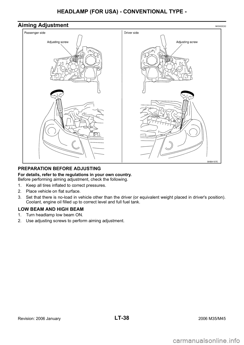
Aiming AdjustmentNKS003OG
PREPARATION BEFORE ADJUSTING
For details, refer to the regulations in your own country.
Before performing aiming adjustment, check the following.
1. Keep all tires inflated to correct pressures.
2. Place vehicle on flat surface.
3. Set that there is no-load in vehicle other than the driver (or equivalent weight placed in driver's position).
Coolant, engine oil filled up to correct level and full fuel tank.
LOW BEAM AND HIGH BEAM
1. Turn headlamp low beam ON.
2. Use adjusting screws to perform aiming adjustment.
SKIB4157E
Page 4501 of 5621

LT-74
HEADLAMP (FOR USA) - XENON TYPE -
Revision: 2006 January2006 M35/M45
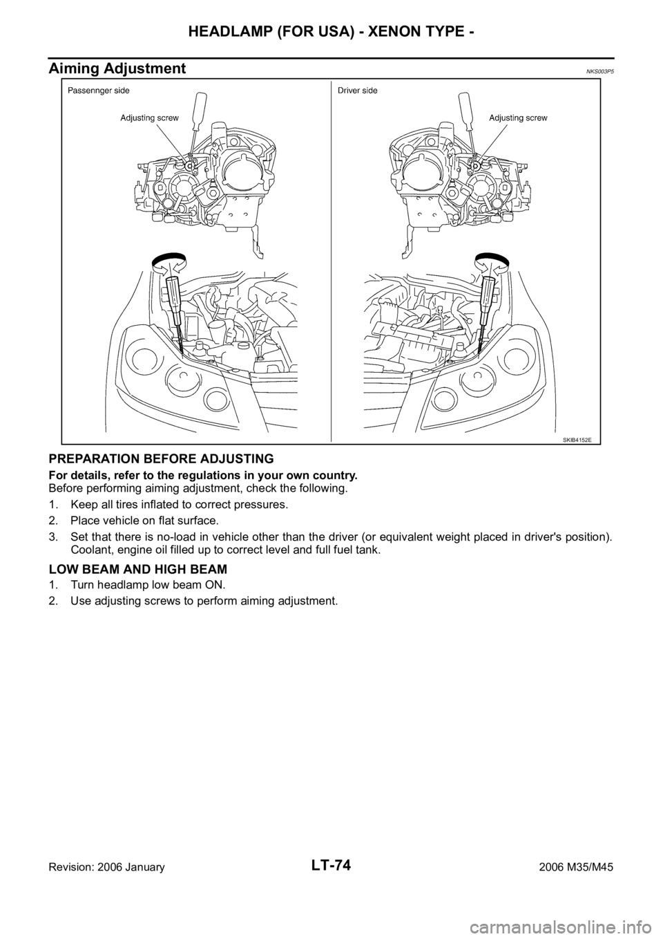
Aiming AdjustmentNKS003P5
PREPARATION BEFORE ADJUSTING
For details, refer to the regulations in your own country.
Before performing aiming adjustment, check the following.
1. Keep all tires inflated to correct pressures.
2. Place vehicle on flat surface.
3. Set that there is no-load in vehicle other than the driver (or equivalent weight placed in driver's position).
Coolant, engine oil filled up to correct level and full fuel tank.
LOW BEAM AND HIGH BEAM
1. Turn headlamp low beam ON.
2. Use adjusting screws to perform aiming adjustment.
SKIB4152E
Page 4636 of 5621

FRONT FOG LAMP
LT-209
C
D
E
F
G
H
I
J
L
MA
B
LT
Revision: 2006 January2006 M35/M45
3. CHECK CAN COMMUNICATIONS BETWEEN BCM AND IPDM E/R
Select “BCM” on CONSULT-II, and perform self-diagnosis for “BCM”.
Display of self-diagnosis results
NO DTC>> Replace IPDM E/R. Refer to PG-31, "Removal and
Installation of IPDM E/R" .
CAN COMM CIRCUIT>> Refer to BCS-15, "
CAN Communication
Inspection Using CONSULT-II (Self-Diagnosis)" .
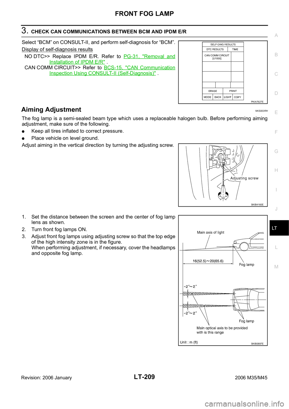
Aiming AdjustmentNKS003RH
The fog lamp is a semi-sealed beam type which uses a replaceable halogen bulb. Before performing aiming
adjustment, make sure of the following.
Keep all tires inflated to correct pressure.
Place vehicle on level ground.
Adjust aiming in the vertical direction by turning the adjusting screw.
1. Set the distance between the screen and the center of fog lamp
lens as shown.
2. Turn front fog lamps ON.
3. Adjust front fog lamps using adjusting screw so that the top edge
of the high intensity zone is in the figure.
When performing adjustment, if necessary, cover the headlamps
and opposite fog lamp.
PKIA7627E
SKIB4160E
SKIB0897E
Page 4782 of 5621

GENERAL MAINTENANCE
MA-5
C
D
E
F
G
H
I
J
K
MA
B
MA
Revision: 2006 January2006 M35/M45
OUTSIDE THE VEHICLE
The maintenance items listed here should be performed from time to time, unless otherwise specified.
INSIDE THE VEHICLE
The maintenance items listed here should be checked on a regular basis, such as when performing periodic maintenance, cleaning the
vehicle, etc.ItemReference page
TiresCheck the pressure with a gauge, including the spare, at least once a month
and always prior to a long distance trips. Adjust to the specified pressure if
necessary. Check carefully for damage, cuts or excessive wear.—
Wheel nutsWhen checking the tires, make sure no nuts are missing, and check for any
loose nuts. Tighten if necessary.—
WindshieldClean the windshield on a regular basis. Check the windshield at least every
six months for cracks or other damage. Repair as necessary.—
Tire rotationTires should be rotated every 12,000 km (7,500 miles).MA-35
Wheel alignment and
balanceIf the vehicle pulls to either side while driving on a straight and level road, or if
you detect uneven or abnormal tire wear, there may be a need for wheel align-
ment. If the steering wheel or seat vibrates at normal highway speeds, wheel
balancing may be needed.MA-33,
FSU-6
(2WD),
FSU-23
(AWD)
Windshield wiper
bladesCheck for cracks or wear if they do not wipe properly. —
Doors and engine
hoodCheck that all doors and the engine hood operate smoothly as well as the
trunk lid. Also make sure that all latches lock securely. Lubricate if necessary.
Make sure that the secondary latch keeps the hood from opening when the pri-
mary latch is released.
When driving in areas using road salt or other corrosive materials, check lubri-
cation frequently.MA-38
LampsMake sure that the headlamps, stop lamps, tail lamps, turn signal lamps, and
other lamps are all operating properly and installed securely. Also check head-
lamp aim. Clean the headlamps on a regular basis. —
ItemReference page
Warning lamps and
chimesMake sure that all warning lamps and chimes are operating properly. —
Windshield wiper and
washerCheck that the wipers and washer operate properly and that the wipers do not
streak.—
Windshield defrosterCheck that the air comes out of the defroster outlets properly and in sufficient
quantity when operating the heater or air conditioner.—
Steering wheelCheck that it has the specified play. Be sure to check for changes in the steer-
ing condition, such as excessive play, hard steering or strange noises.
Free play: Less than 35 mm (1.38 in)—
SeatsCheck seat position controls such as seat adjusters, seatback recliner, etc. to
make sure they operate smoothly and that all latches lock securely in every
position. Check that the head restrains move up and down smoothly and that
the locks (if equipped) hold securely in all latched positions. Check that the
latches lock securely for folding-down rear seatbacks.—
Seat beltsCheck that all parts of the seat belt system (e.g. buckles, anchors, adjusters
and retractors) operate properly and smoothly, and are installed securely.
Check the belt webbing for cuts, fraying, wear or damage.MA-39
Accelerator pedalCheck the pedal for smooth operation and make sure the pedal does not catch
or require uneven effort. Keep the floor mats away from the pedal.—
BrakesCheck that the brake does not pull the vehicle to one side when applied. —
Brake pedal and
boosterCheck the pedal for smooth operation and make sure it has the proper dis-
tance under it when depressed fully. Check the brake booster function. Be
sure to keep the floor mats away from the pedal.BR-6
, BR-18
Page 4799 of 5621

MA-22
ENGINE MAINTENANCE (VK45DE ENGINE)
Revision: 2006 January2006 M35/M45
ENGINE MAINTENANCE (VK45DE ENGINE)PFP:10001
Checking Drive BeltsNLS0007Q
WAR NING :
Be sure to perform when the engine is stopped.
Remove air duct (inlet) when inspecting drive belt for alternator, water pump and A/C compressor.
Remove front engine undercover with power tool when inspecting power steering oil pump belt.
Make sure that indicator (single line notch) of each auto tensioner is within the allowable working range
(between three line notches).
NOTE:
Check auto tensioner indication when engine is cold.
When new drive belt is installed, the range should be “A”.
The indicator notch is located on the moving side of the tensioner for alternator, water pump and A/C
compressor belt, while it is found on the fixed side for power steering oil pump belt.
Visually check entire belt for wear, damage or cracks.
If the indicator is out of allowable working range or belt is damaged, replace belt.
Te n s i o n A d j u s t m e n tNLS0007R
Belt tensioning is not necessary, as it is automatically adjusted by auto tensioner.
Changing Engine CoolantNLS0007S
WAR NING :
To avoid being scalded, do not change engine coolant when engine is hot.
Wrap a thick cloth around radiator cap and carefully remove radiator cap. First, turn radiator cap a
quarter of a turn to release built-up pressure. Then turn radiator cap all the way.
Be careful not to allow engine coolant to contact drive belts.
DRAINING ENGINE COOLANT
1. Remove engine room cover (RH and LH) Refer to EM-173, "ENGINE ROOM COVER" .
2. Remove engine cover with power tool. Refer to EM-179, "
INTAKE MANIFOLD" .
3. Open radiator drain plug at the bottom of radiator, and then remove radiator cap.
PBIC3822E