engine INFINITI M35 2006 Factory Service Manual
[x] Cancel search | Manufacturer: INFINITI, Model Year: 2006, Model line: M35, Model: INFINITI M35 2006Pages: 5621, PDF Size: 65.56 MB
Page 4860 of 5621
PDU (POWER DISTRIBUTION UNIT)
PG-33
C
D
E
F
G
H
I
J
L
MA
B
PG
Revision: 2006 January2006 M35/M45
PDU (POWER DISTRIBUTION UNIT)PFP:285F1
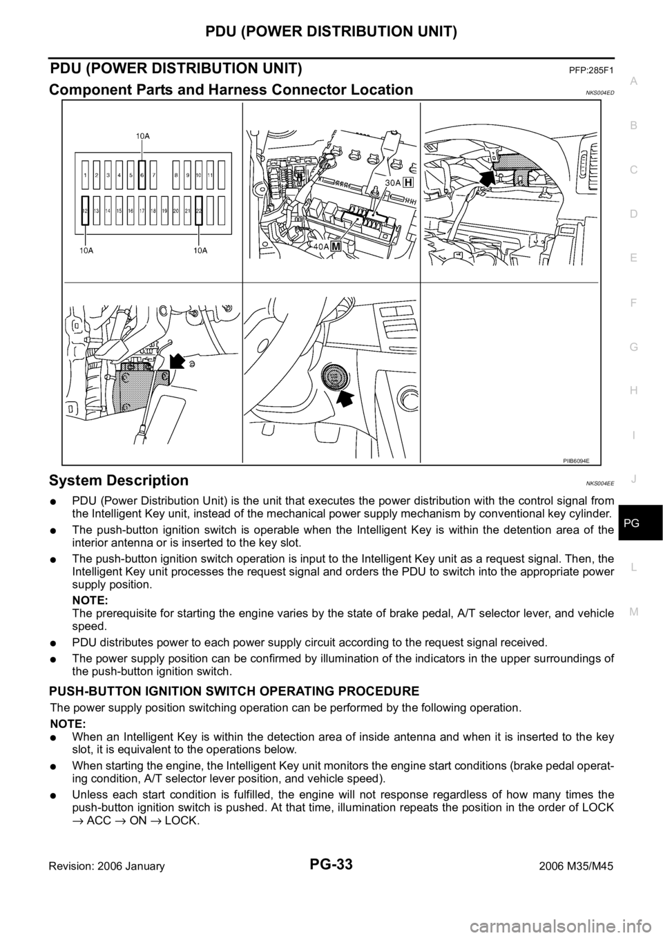
Component Parts and Harness Connector LocationNKS004ED
System DescriptionNKS004EE
PDU (Power Distribution Unit) is the unit that executes the power distribution with the control signal from
the Intelligent Key unit, instead of the mechanical power supply mechanism by conventional key cylinder.
The push-button ignition switch is operable when the Intelligent Key is within the detention area of the
interior antenna or is inserted to the key slot.
The push-button ignition switch operation is input to the Intelligent Key unit as a request signal. Then, the
Intelligent Key unit processes the request signal and orders the PDU to switch into the appropriate power
supply position.
NOTE:
The prerequisite for starting the engine varies by the state of brake pedal, A/T selector lever, and vehicle
speed.
PDU distributes power to each power supply circuit according to the request signal received.
The power supply position can be confirmed by illumination of the indicators in the upper surroundings of
the push-button ignition switch.
PUSH-BUTTON IGNITION SWITCH OPERATING PROCEDURE
The power supply position switching operation can be performed by the following operation.
NOTE:
When an Intelligent Key is within the detection area of inside antenna and when it is inserted to the key
slot, it is equivalent to the operations below.
When starting the engine, the Intelligent Key unit monitors the engine start conditions (brake pedal operat-
ing condition, A/T selector lever position, and vehicle speed).
Unless each start condition is fulfilled, the engine will not response regardless of how many times the
push-button ignition switch is pushed. At that time, illumination repeats the position in the order of LOCK
ACC ON LOCK.
PIIB6094E
Page 4861 of 5621

PG-34
PDU (POWER DISTRIBUTION UNIT)
Revision: 2006 January2006 M35/M45
*1: When the A/T selector lever position is N position, the engine start condition is different according to the vehicle speed.
At vehicle speed of 5 km/h or less, the engine can start only when the brake pedal is depressed.
At vehicle speed of 5 km/h or more, the engine can start even if the brake pedal is not depressed. (It is the same as “Engine stall
return operation while driving”.)
*2: When the A/T selector lever position is any position other than P position and when the vehicle speed is 5 km/h or more, the engine
stop condition is different.
Press and hold the push-button ignition switch for 2 seconds or more. (When the push-button ignition switch is pressed for too short
a time, the operation may be invalid, so properly press and hold to prevent the incorrect operation.)
Press the push-button ignition switch 3 times within 1.5 seconds. (Emergency stop operation) Power supply positionEngine start/stop condition Push-button ignition
switch operation fre-
quency Brake pedal operation condition A/T selector lever position
LOCK
ACCNot depressed
(When A/T selector lever is in any posi-
tion other than P or N, there will be no
effect even if it is depressed.)Any position other than P or N
(When the brake pedal is not
depressed, there will be no effect even
if the A/T selector lever is in P or N
position.)1
LOCK
ACC ONNot depressed
(When A/T selector lever is in any posi-
tion other than P or N, there will be no
effect even if it is depressed.)Any position other than P or N
(When the brake pedal is not
depressed, there will be no effect even
if the A/T selector lever is in P or N
position.)2
LOCK
ACC ON
LOCKNot depressed
(When A/T selector lever is in any posi-
tion other than P or N, there will be no
effect even if it is depressed.)Any position other than P or N
(When the brake pedal is not
depressed, there will be no effect even
if the A/T selector lever is in P or N
position.)3
LOCK
START
ACC
START
ON
START
(Engine start)Depressed P or N position (*1)1
[If the switch is
pushed once, the
engine starts from
any power supply
position (LOCK,
ACC, and ON)]
Engine start condition
LOCK
(Engine stop)— P position 1
Engine start condition
ACC
(Engine stop)— Any position other than P (*2) 1
Engine stall return
operation while driving— N position 1
Page 4864 of 5621

PDU (POWER DISTRIBUTION UNIT)
PG-37
C
D
E
F
G
H
I
J
L
MA
B
PG
Revision: 2006 January2006 M35/M45
Terminals and Reference Value for Intelligent Key UnitNKS004EG
Te r m i -
nalWire
ColorItemCondition
Voltage (V)
Approx. Ignition
Switch
PositionOperation or Conditions
1 SB Power source (Fuse) LOCK — Battery voltage
3 Y IPDM E/R status signal —Engine starting (During Cranking) 5
Other than above 2
8WPush-button ignition
switch
(LOCK LED)LOCK Push-button ignition switch is in LOCK position 0
—Push-button ignition switch is in any position
(Except LOCK position)1.2
9LPush-button ignition
switch
(ACC LED)ACC Push-button ignition switch is in ACC position 0
—Push-button ignition switch is in any position
(Except ACC position)1.2
10 VPush-button ignition
switch
(ON LED)ON Push-button ignition switch is in ON position 0
—Push-button ignition switch is in any position
(Except ON position)1.2
20 B Ground — — 0
30 L/W Ignition switch (ACC) ACC — Battery voltage
31 GR Ignition switch (ON) ON — Battery voltage
34 R PDU feedback signal LOCKPush-button ignition switch is in LOCK state, 30 sec-
onds after all doors closed1
Other than above 0
36 W Ignition signal 2LOCK — Battery voltage
ACC — Battery voltage
ON — 0
37 P CAN-L — — —
38 L CAN-H — — —
39 BR/W Push switch —Depress push-button ignition switch 0
Unpress push-button ignition switch Battery voltage
40 B Ground — — 0
41 Y Power source (Fuse) LOCK — Battery voltage
42 P PDU wake up signal LOCKPush-button ignition switch is in LOCk state, 30 sec-
onds after all doors closedBattery voltage
Other than above 0
44 BR Ignition signal 1LOCK — Battery voltage
ACC — Battery voltage
ON — 0
45 SB ACC signalLOCK — Battery voltage
ACC — 0
ON — 0
56 B Ground — — 0
57 L Power source (Fuse) LOCK — Battery voltage
72 B Ground — — 0
Page 4865 of 5621

PG-38
PDU (POWER DISTRIBUTION UNIT)
Revision: 2006 January2006 M35/M45
Terminals and Reference Value for PDUNKS004EH
Work FlowNKS004EI
1. Check the symptom and customer's requests.
2. Understand outline of system. Refer to PG-33, "
System Description" .
3. Confirm that Intelligent Key system operates normally.
Refer to BL-24, "
POWER DOOR LOCK SYSTEM" .
4. Repair or replace any malfunctioning parts.
Refer to PG-39, "
Trouble Diagnosis Symptom Chart" .
5. INSPECTION END
Te r m i -
nalWire
ColorItemCondition
Voltage (V)
Approx. Ignition
Switch
PositionOperation or Conditions
1 P PDU wake up signal LOCKPush-button ignition switch is in LOCK state, 30 sec-
onds after all doors closeBattery voltage
Other than above 0
4 BR Ignition signal 1LOCK — Battery voltage
ACC — Battery voltage
ON — 0
5 W Ignition signal 2LOCK — Battery voltage
ACC — Battery voltage
ON — 0
8 SB ACC signalLOCK — Battery voltage
ACC — 0
ON — 0
10 B Ground — — 0
11 Y IPDM E/R status signal —Engine starting (During Cranking) 5
Other than above 2
12 R PDU feedback signal LOCKPush-button ignition switch is in LOCK state, 30 sec-
onds after all doors close1
Other than above 0
14 SB Power source (Fuse) LOCK — Battery voltage
15 L Power source (F/L) LOCK — Battery voltage
16 W ACC power outputLOCK — 0
ACC — Battery voltage
ON — Battery voltage
17 G Power source (Fuse) LOCK — Battery voltage
18 BR ON power outputLOCK — 0
ACC — 0
ON — Battery voltage
Page 4878 of 5621
GROUND
PG-51
C
D
E
F
G
H
I
J
L
MA
B
PG
Revision: 2006 January2006 M35/M45
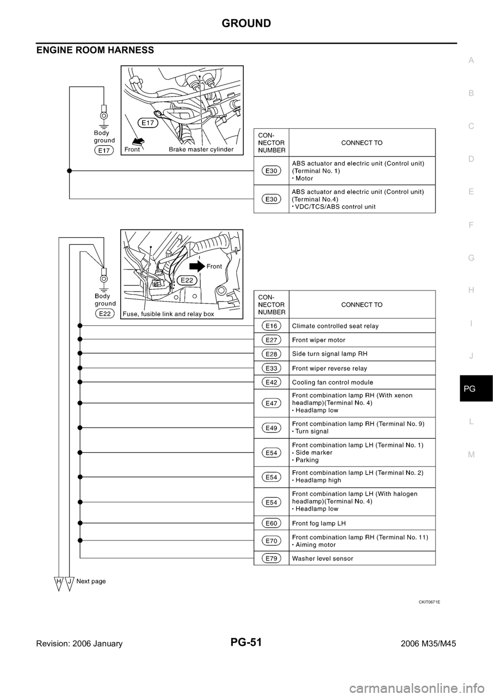
ENGINE ROOM HARNESS
CKIT0671E
Page 4882 of 5621
GROUND
PG-55
C
D
E
F
G
H
I
J
L
MA
B
PG
Revision: 2006 January2006 M35/M45
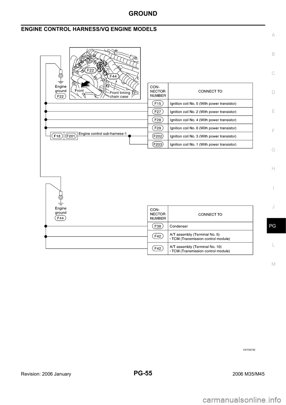
ENGINE CONTROL HARNESS/VQ ENGINE MODELS
CKIT0675E
Page 4883 of 5621
PG-56
GROUND
Revision: 2006 January2006 M35/M45
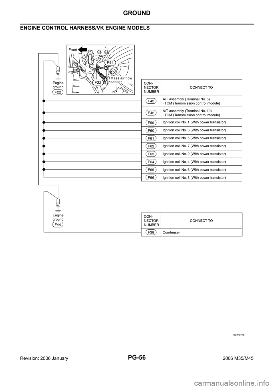
ENGINE CONTROL HARNESS/VK ENGINE MODELS
CKIT0676E
Page 4890 of 5621
HARNESS
PG-63
C
D
E
F
G
H
I
J
L
MA
B
PG
Revision: 2006 January2006 M35/M45
HARNESS PFP:00011
Harness Layout NKS004ES
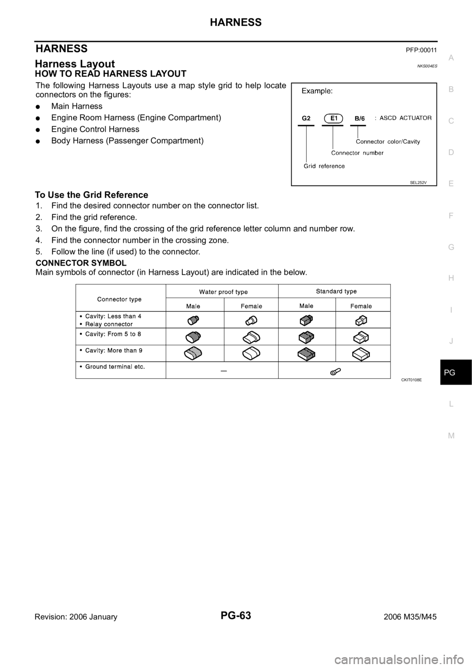
HOW TO READ HARNESS LAYOUT
The following Harness Layouts use a map style grid to help locate
connectors on the figures:
Main Harness
Engine Room Harness (Engine Compartment)
Engine Control Harness
Body Harness (Passenger Compartment)
To Use the Grid Reference
1. Find the desired connector number on the connector list.
2. Find the grid reference.
3. On the figure, find the crossing of the grid reference letter column and number row.
4. Find the connector number in the crossing zone.
5. Follow the line (if used) to the connector.
CONNECTOR SYMBOL
Main symbols of connector (in Harness Layout) are indicated in the below.
SEL252V
CKIT0108E
Page 4898 of 5621
HARNESS
PG-71
C
D
E
F
G
H
I
J
L
MA
B
PG
Revision: 2006 January2006 M35/M45
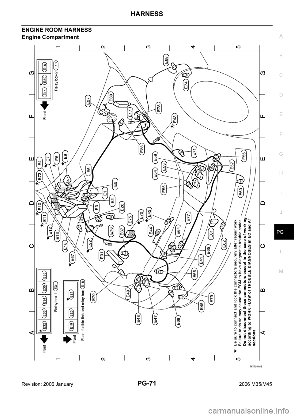
ENGINE ROOM HARNESS
Engine Compartment
TKIT0448E
Page 4902 of 5621
HARNESS
PG-75
C
D
E
F
G
H
I
J
L
MA
B
PG
Revision: 2006 January2006 M35/M45
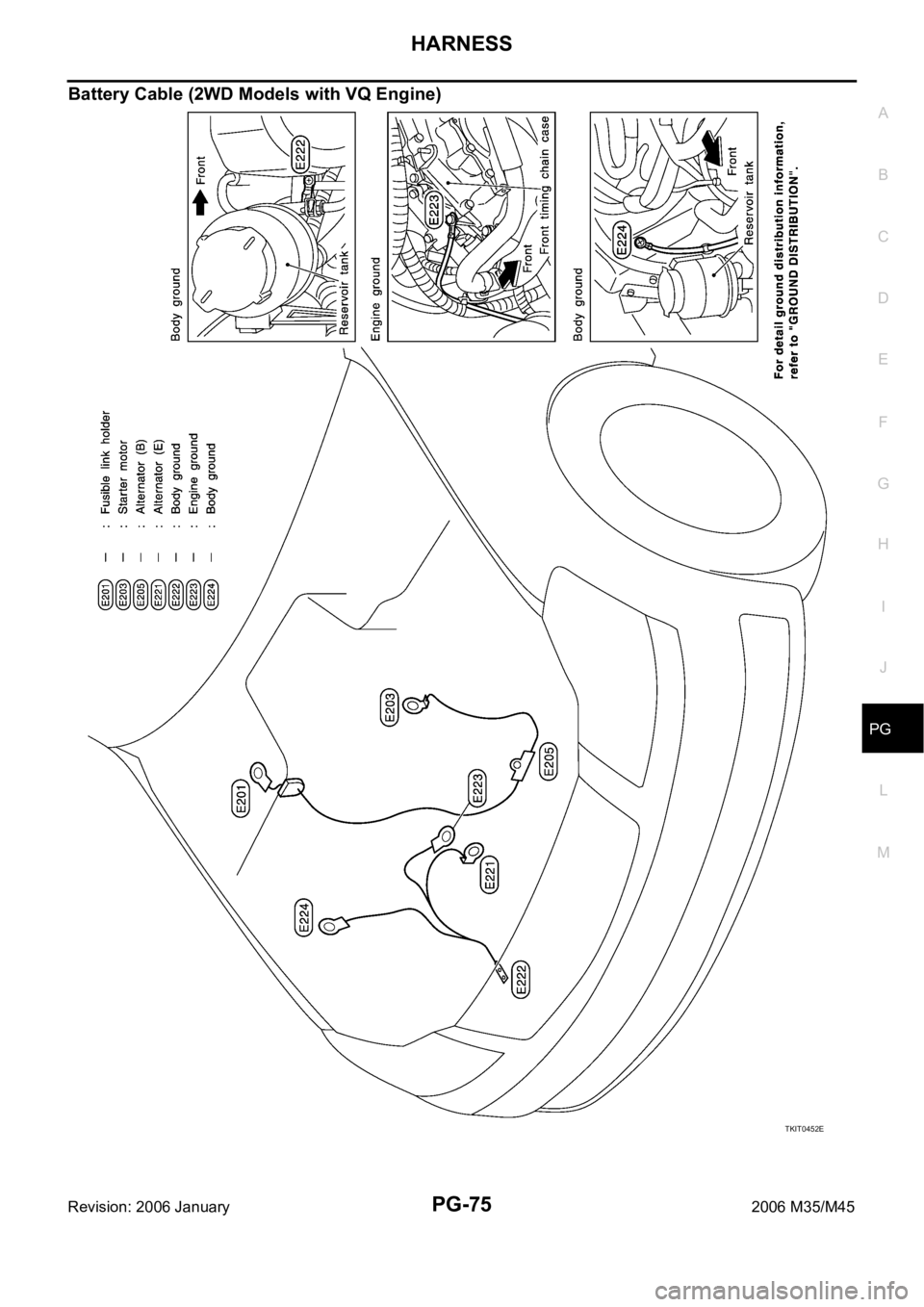
Battery Cable (2WD Models with VQ Engine)
TKIT0452E