starting INFINITI M35 2006 Factory Service Manual
[x] Cancel search | Manufacturer: INFINITI, Model Year: 2006, Model line: M35, Model: INFINITI M35 2006Pages: 5621, PDF Size: 65.56 MB
Page 5152 of 5621

STARTING SYSTEM
SC-15
C
D
E
F
G
H
I
J
L
MA
B
SC
Revision: 2006 January2006 M35/M45
DIAGNOSTIC PROCEDURE 1
Check “B” Terminal Circuit
CAUTION:
Perform diagnosis under the condition that engine cannot start by the following procedure.
1. Remove fuel pump fuse.
2. Crank or start the engine (where possible) until the fuel pressure is released.
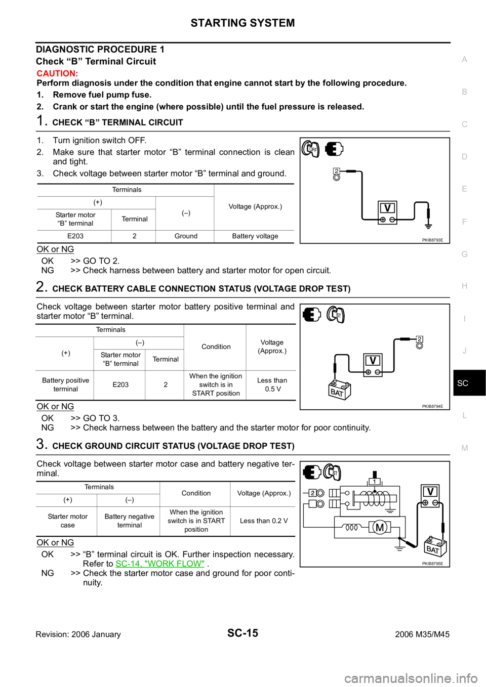
1. CHECK “B” TERMINAL CIRCUIT
1. Turn ignition switch OFF.
2. Make sure that starter motor “B” terminal connection is clean
and tight.
3. Check voltage between starter motor “B” terminal and ground.
OK or NG
OK >> GO TO 2.
NG >> Check harness between battery and starter motor for open circuit.
2. CHECK BATTERY CABLE CONNECTION STATUS (VOLTAGE DROP TEST)
Check voltage between starter motor battery positive terminal and
starter motor “B” terminal.
OK or NG
OK >> GO TO 3.
NG >> Check harness between the battery and the starter motor for poor continuity.
3. CHECK GROUND CIRCUIT STATUS (VOLTAGE DROP TEST)
Check voltage between starter motor case and battery negative ter-
minal.
OK or NG
OK >> “B” terminal circuit is OK. Further inspection necessary.
Refer to SC-14, "
WORK FLOW" .
NG >> Check the starter motor case and ground for poor conti-
nuity.
Terminals
Voltage (Approx.) (+)
(–)
Starter motor
“B” terminalTerminal
E203 2 Ground Battery voltage
PKIB8793E
Terminals
ConditionVoltage
(Approx.)
(+)(–)
Starter motor
“B” terminalTerminal
Battery positive
terminalE203 2 When the ignition
switch is in
START positionLess than
0.5 V
PKIB8794E
Terminals
Condition Voltage (Approx.)
(+) (–)
Starter motor
caseBattery negative
terminalWhen the ignition
switch is in START
positionLess than 0.2 V
PKIB8795E
Page 5153 of 5621

SC-16
STARTING SYSTEM
Revision: 2006 January2006 M35/M45
DIAGNOSTIC PROCEDURE 2
Check “S” Connector Circuit
CAUTION:
Perform diagnosis under the condition that engine cannot start by the following procedure.
1. Remove fuel pump fuse.
2. Crank or start the engine (where possible) until the fuel pressure is released.
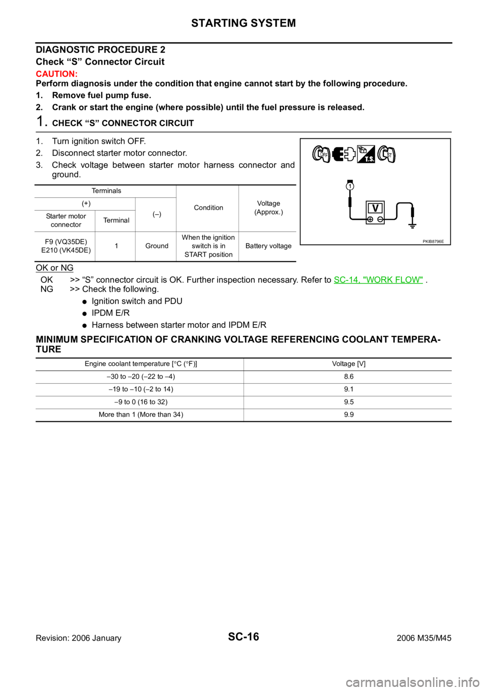
1. CHECK “S” CONNECTOR CIRCUIT
1. Turn ignition switch OFF.
2. Disconnect starter motor connector.
3. Check voltage between starter motor harness connector and
ground.
OK or NG
OK >> “S” connector circuit is OK. Further inspection necessary. Refer to SC-14, "WORK FLOW" .
NG >> Check the following.
Ignition switch and PDU
IPDM E/R
Harness between starter motor and IPDM E/R
MINIMUM SPECIFICATION OF CRANKING VOLTAGE REFERENCING COOLANT TEMPERA-
TURE
Te r m i n a l s
ConditionVoltage
(Approx.) (+)
(–)
Starter motor
connectorTe r m i n a l
F9 (VQ35DE)
E210 (VK45DE)1 GroundWhen the ignition
switch is in
START positionBattery voltage
PKIB8796E
Engine coolant temperature [C (F)] Voltage [V]
30 to 20 (22 to 4) 8.6
19 to 10 (2 to 14) 9.1
9 to 0 (16 to 32) 9.5
More than 1 (More than 34) 9.9
Page 5154 of 5621

STARTING SYSTEM
SC-17
C
D
E
F
G
H
I
J
L
MA
B
SC
Revision: 2006 January2006 M35/M45
Removal and Installation NKS003NL
VQ35DE ENGINE MODELS (2WD)
Removal
1. Disconnect the battery cable from the negative terminal.
2. Remove engine front and rear undercover, using power tools.
3. Remove “B” terminal nut (1).
4. Disconnect “S” connector (2).
5. Remove starter motor mounting bolts (A), using power tools.
6. Remove starter motor downward from the vehicle.
Installation
Installation is the reverse order of removal.
CAUTION:
Be sure to tighten “B” terminal nut carefully.
1. Starter motor mounting bolt 2. Harness clip bracket 3. “S” connector
4. “B” terminal nut 5. “B” terminal harness 6. Starter motor
7. Oil pan : Nꞏm (kg-m, ft-lb) : Nꞏm (kg-m, in-lb)
: Engine front
PKIB8799E
PKIB8800E
Page 5155 of 5621

SC-18
STARTING SYSTEM
Revision: 2006 January2006 M35/M45
VQ35DE ENGINE MODELS (AWD)
Removal
1. Disconnect the battery cable from the negative terminal.
2. Remove engine rear undercover, using power tools.
3. Remove exhaust mounting bracket. Refer to EM-183, "
EXHAUST MANIFOLD AND THREE WAY CATA-
LY S T" .
4. Remove “B” terminal nut (1).
5. Disconnect “S” connector (1).
6. Remove starter motor mounting bolts (A) and harness bracket
(2), using power tools.
7. Remove starter motor downward from the vehicle.
Installation
Installation is the reverse order of removal.
CAUTION:
Be sure to tighten “B” terminal nut carefully.
1. Starter motor mounting bolt 2. Oil pan 3. Starter motor
4. “B” terminal harness 5. “B” terminal nut 6. “S” connector
: Nꞏm (kg-m, ft-lb) : Engine front
PKIB8801E
PKIB8802E
PKIB8803E
Page 5156 of 5621

STARTING SYSTEM
SC-19
C
D
E
F
G
H
I
J
L
MA
B
SC
Revision: 2006 January2006 M35/M45
VK45DE ENGINE MODELS
Removal
1. Disconnect the battery cable from the negative terminal.
2. Remove engine front and rear undercover, using power tools.
3. Remove left engine mounting insulator and left engine mounting
bracket. Refer to EM-244, "
ENGINE ASSEMBLY" .
4. Remove “B” terminal nut (1).
5. Disconnect “S” connector (2).
6. Remove the bolt (A) and the harness bracket (3).
7. Remove starter motor mounting bolts (B), using power tools.
8. Remove starter motor forward from the vehicle.
Installation
Installation is the reverse order of removal.
CAUTION:
Be sure to tighten “B” terminal nut carefully.
1. Starter motor 2. Starter motor mounting bolt 3. “S” connector
4. “B” terminal harness 5. “B” terminal nut 6. Cylinder block
: Nꞏm (kg-m, ft-lb) : Engine front
PKIB8797E
PKIB8798E
Page 5157 of 5621

SC-20
STARTING SYSTEM
Revision: 2006 January2006 M35/M45
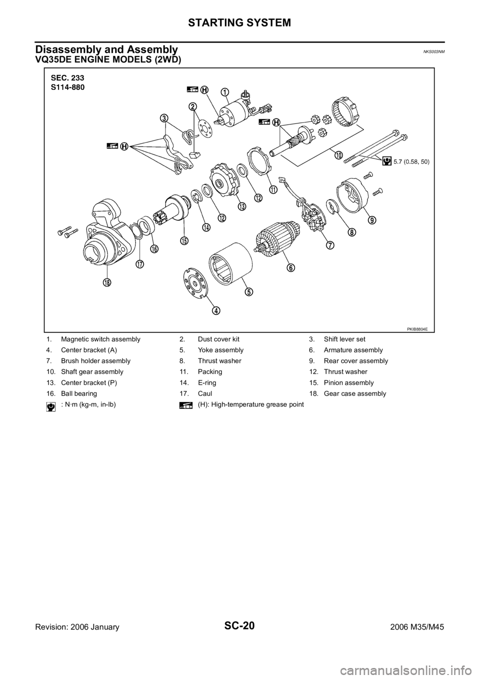
Disassembly and Assembly NKS003NM
VQ35DE ENGINE MODELS (2WD)
1. Magnetic switch assembly 2. Dust cover kit 3. Shift lever set
4. Center bracket (A) 5. Yoke assembly 6. Armature assembly
7. Brush holder assembly 8. Thrust washer 9. Rear cover assembly
10. Shaft gear assembly 11. Packing 12. Thrust washer
13. Center bracket (P) 14. E-ring 15. Pinion assembly
16. Ball bearing 17. Caul 18. Gear case assembly
: Nꞏm (kg-m, in-lb)
(H): High-temperature grease point
PKIB8804E
Page 5158 of 5621

STARTING SYSTEM
SC-21
C
D
E
F
G
H
I
J
L
MA
B
SC
Revision: 2006 January2006 M35/M45
VQ35DE ENGINE MODELS (AWD)
1. Magnetic switch assembly 2. Dust cover kit 3. Shift lever set
4. Center bracket (A) 5. Yoke assembly 6. Armature assembly
7. Brush holder assembly 8. Thrust washer 9. Rear cover assembly
10. Shaft gear assembly 11. Packing 12. Thrust washer
13. Center bracket (P) 14. E-ring 15. Pinion assembly
16. Ball bearing 17. Caul 18. Gear case assembly
: Nꞏm (kg-m, in-lb)
(H): High-temperature grease point
PKIB8805E
Page 5159 of 5621

SC-22
STARTING SYSTEM
Revision: 2006 January2006 M35/M45
VK45DE ENGINE MODELS
INSPECTION AFTER DISASSEMBLY
Pinion/Clutch Check
1. Inspect pinion teeth.
Replace pinion if teeth are worn or damaged. (Also check condition of ring gear teeth.)
2. Inspect reduction gear teeth.
Replace reduction gear if teeth are worn or damaged. (Also check condition of armature shaft gear
teeth.)
3. Check to see if pinion locks in one direction and rotates smoothly in the opposite direction.
If it locks or rotates in both directions, or unusual resistance is evident, replace.
1. Magnetic switch assembly 2. Adjusting plate 3. Packing
4. Plate 5. Shift lever 6. Sleeve bearing
7. Front bracket assembly 8. Yoke assembly 9. Armature assembly
10. Washer 11. Rear bearing 12. Brush holder assembly
13. Rear bracket assembly 14. Cover 15. Packing
16. Ball 17. Shaft gear assembly 18. Clutch gear assembly
19. Pinion stopper 20. Stopper clip
: Nꞏm (kg-m, in-lb) (H): High-temperature grease point
PKIB8653E
Page 5165 of 5621

SC-28
CHARGING SYSTEM
Revision: 2006 January2006 M35/M45
Trouble Diagnoses with Battery/Starting/Charging System Tester (Charging)NKS003NP
NOTE:
To ensure a complete and thorough diagnosis, the battery, starter and alternator test segments must be done
as a set from start to finish.
Before starting, perform the preliminary inspection. Refer to SC-32, "
PRELIMINARY INSPECTION" .
1. Stop the operation of the power generation voltage variable control in either of the following procedures.
After selecting “ENGINE” of “SELECT SYSTEM” using CONSULT-II, set the DUTY value of “ALTERNA-
TOR DUTY” to 0% by selecting “ALTERNATOR DUTY” of “ACTIVE TEST”. Continue “ACTIVE TEST”
until the end of inspection. (When the DUTY value is 0 or 100%, the normal power generation is per-
formed according to the characteristic of the IC regulator of the alternator.)
Turn the ignition switch OFF, and disconnect the battery current sensor connector. [However, DTC
(P1550 - P1554) of the engine might remain. After finishing the inspection, connect the battery current
sensor connector and erase the self-diagnostic results history of the engine using CONSULT-II.]
2. Turn off all loads on the vehicle electrical system.
3. Perform battery and starting system test with Battery/Starting/
Charging system tester.
4. Press “ENTER” to begin the charging system test.
5. Start engine.
6. Press “ENTER” until “LOADS OFF REV ENGINE 5 SEC” is dis-
played.
7. Raise and hold the engine speed at 1,500 to 2,000 rpm for about
5 seconds, then return the engine to idle.
Once the increase in engine rpm is detected, press “ENTER” to
continue.
NOTE:
If after 30 seconds an increase in engine idle speed is not
detected, “RPM NOT DETECTED” will display.
Some engines may have a higher idle initially after starting,
particularly when the engine is cold. The tester may detect
this without any other action being taken. If this occurs, con-
tinue on with the testing process. The final results will not be affected.
8. The tester now checks the engine at idle and performs the
DIODE/RIPPLE check.
9. When complete, the tester will prompt you to turn on the follow-
ing electrical loads.
Heater fan set to highest speed. Do not run the A/C or wind-
shield defroster.
Headlamp high beam
Rear window defogger
NOTE:
Do not run the windshield wipers or any other cyclical loads.
SEL417X
SEL418X
SEL419X
Page 5167 of 5621

SC-30
CHARGING SYSTEM
Revision: 2006 January2006 M35/M45
DIAGNOSTIC RESULT ITEM CHART
Diagnostic item Service procedure
CHARGING SYSTEM NORMAL Charging system is normal and will also show “DIODE RIPPLE” test result.
NO CHARGING VOLTAGE
Go to SC-31, "
WORK FLOW" . LOW CHARGING VOLTAGE
HIGH CHARGING VOLTAGE
DIODE RIPPLE NORMAL Diode ripple is OK and will also show “CHARGING VOLTAGE” test result.
EXCESS RIPPLE DETECTEDReplace the alternator. Perform “DIODE RIPPLE” test again using Battery/Starting/Charging
system tester to confirm repair.
DIODE RIPPLE NOT DETECTED Go to SC-31, "
WORK FLOW" .