ESP INFINITI M35 2006 Factory Service Manual
[x] Cancel search | Manufacturer: INFINITI, Model Year: 2006, Model line: M35, Model: INFINITI M35 2006Pages: 5621, PDF Size: 65.56 MB
Page 5295 of 5621

SE-114
CLIMATE CONTROLLED SEAT
Revision: 2006 January2006 M35/M45
At the time of work, please turn OFF a switch, and carry it out after checking that the thermal elec-
tric device has got cold.
Power is at all times supplied
through 15A fuse [No. 41 located in the fuse fusible link and relay unit]
to climate controlled seat relay terminals 5.
through 15A fuse [No. 42 located in the fuse fusible link and relay unit]
to climate controlled seat relay terminals 7.
When the ignition switch turned to ON or START position,
Power is supplied
through 10A fuse [No. 12, located in the fuse block (J/B)]
to climate controlled seat relay terminal 2.
Then ground is supplied
to climate controlled seat relay terminal 1,
through body grounds E22 and E43.
Then climate controlled seat relay is energized.
When climate controlled seat relay is turned to ON,
Power is supplied,
through climate controlled seat relay terminal 3,
to climate controlled seat control unit (passenger side) terminal 2 and 4.
through climate controlled seat relay terminal 6,
to climate controlled seat control unit (driver side) terminal 2 and 4.
When climate controlled switch select HEAT, ground is supplied
through climate controlled seat switch terminal 1 and 3,
to climate controlled seat control unit terminal 10.
Then, the climate controlled seat control unit receives climate controlled seat switch HEAT signal.
When climate controlled seat switch select COOL, ground is supplied
through climate controlled seat switch terminal 1 and 2,
to climate controlled seat control unit terminal 20,
Then, the climate controlled seat control unit receives climate controlled switch COOL signal.
When blower motor rotates, signal is transmitted
to climate controlled seat control unit terminal 18,
through climate controlled seat blower motor terminal 1.
This is climate controlled seat blower motor tachometer signal.
When climate controlled seat control unit receives climate controlled seat switch signal and tachometer signal,
Power is supplied
to climate controlled seat blower motor terminal 4,
through climate controlled seat control unit terminal 17.
This is blower motor revolution control signal.
When blower motor receivers blower motor revolution control signal,
Power is supplied
through climate controlled seat control unit terminal 14,
to climate controlled seat blower motor terminal 2.
When number of rotations correspond signal,
Ground is supplied
to climate controlled seat blower motor terminal 3,
through climate controlled seat control unit terminal 7,
through climate controlled seat control unit terminal 3,
through body grounds B5, B40 and B131.
Then motor revolution is controlled.
When the ignition switch turned to ON or START position,
Power is supplied
Page 5389 of 5621

SRS-28
TROUBLE DIAGNOSIS
Revision: 2006 January2006 M35/M45
3. Touch “TROUBLE DIAG RECORD”.
NOTE:
With “TROUBLE DIAG RECORD”, diagnosis results previously
erased by a reset operation can be displayed.
4. Diagnostic code is displayed on “TROUBLE DIAG RECORD”.
5. Touch “PRINT”.
6. Compare diagnostic codes to SRS-28, "
CONSULT-II Diagnostic
Code Chart (“SELF-DIAG [PAST]” or “TROUBLE DIAG
RECORD”)" .
7. Touch “BACK” key of CONSULT-II until “SELECT SYSTEM”
appears.
8. Turn ignition switch OFF, then turn off and disconnect CON-
SULT-II, and both battery cables.
9. Repair the system as outlined by the “Repair order” in “Intermit-
tent Malfunction Diagnostic Code Chart”, that corresponds to the
self-diagnosis result. For replacement procedure of component parts, refer to the Removal and Installa-
tion procedure for the appropriate component.
10. Go to SRS-25, "
DIAGNOSTIC PROCEDURE 3" , for final checking.
CONSULT-II Diagnostic Code Chart (“SELF-DIAG [PAST]” or “TROUBLE DIAG RECORD”)
SRS697
SHIA0182E
Diagnostic item ExplanationRepair order
“Recheck SRS at each replacement”
NO DTC IS
DETECTED.When malfunction is
indicated by the “AIR
BAG” warning lamp in
User mode.
Low battery voltage (Less than 9V)Go to SRS-25, "DIAGNOSTIC PRO-
CEDURE 3" .
No malfunction is detected.Go to SRS-25, "DIAGNOSTIC PRO-
CEDURE 3" .
DRIVER AIRBAG
MODULE
[OPEN]
Driver air bag module circuit is open (including the spiral cable). 1. Visually check the wiring harness
connection.
2. Replace the harness if it has visible
damage.
3. If the harness check result is OK,
replace driver air bag module, diag-
nosis sensor unit and spiral cable. DRIVER AIRBAG
MODULE
[VB-SHORT]
Driver air bag module circuit is shorted to a power supply circuit
(including the spiral cable).
DRIVER AIRBAG
MODULE
[GND-SHORT]
Driver air bag module circuit is shorted to ground (including the
spiral cable).
DRIVER AIRBAG
MODULE
[SHORT]
Driver air bag module circuit is shorted between lines.
ASSIST A/B MODULE
[OPEN]
Front passenger air bag module circuit is open. 1. Visually check the wiring harness
connection.
2. Replace the harness if it has visible
damage.
3. If the harness check result is OK,
replace the diagnosis sensor unit
and front passenger air bag module. ASSIST A/B MODULE
[VB-SHORT]
Front passenger air bag module circuit is shorted to a power
supply circuit.
ASSIST A/B MODULE
[GND-SHORT]
Front passenger air bag module circuit is shorted to ground.
ASSIST A/B MODULE
[SHORT]
Front passenger air bag module circuit is shorted between lines.
Page 5442 of 5621
![INFINITI M35 2006 Factory Service Manual TROUBLE DIAGNOSIS
STC-27
[RAS]
C
D
E
F
H
I
J
K
L
MA
B
STC
Revision: 2006 January2006 M35/M45
STANDARD BY CONSULT-II
CAUTION:
The output signal indicates the RAS control unit calculation data. The norm INFINITI M35 2006 Factory Service Manual TROUBLE DIAGNOSIS
STC-27
[RAS]
C
D
E
F
H
I
J
K
L
MA
B
STC
Revision: 2006 January2006 M35/M45
STANDARD BY CONSULT-II
CAUTION:
The output signal indicates the RAS control unit calculation data. The norm](/img/42/57023/w960_57023-5441.png)
TROUBLE DIAGNOSIS
STC-27
[RAS]
C
D
E
F
H
I
J
K
L
MA
B
STC
Revision: 2006 January2006 M35/M45
STANDARD BY CONSULT-II
CAUTION:
The output signal indicates the RAS control unit calculation data. The normal values will be displayed
even in the event that the output circuit (harness) is open.
Monitor itemDATA MONITOR
Malfunction inspection
checklist
Condition Reference values
VHCL SPEED SE (km/h)Ignition switch ON or engine
running Almost in accordance with the speed-
ometer display. It is not a malfunction,
through it might not be corresponding
just after ignition switch is turned ON.STC-38, "
Inspection 4:
Vehicle Speed Signal"
STEERING ANG ()Turning steering wheel clock-
wise or counterclockwise.Displays the angle when the steering
wheel turns from the neutral positionSTC-38, "
Inspection 5:
Steering Angle Signal
Malfunction"
ENGINE SPEED (rpm) Engine runningAlmost in accordance with tachometer
displaySTC-43, "
Inspection 8:
Engine Speed Signal
Malfunction"
POWER STR SOL (A)Accelerate the vehicle from 0
to 100 km/h (0 to 62 MPH)0 km/h (0 MPH): Approx. 1.10 A
100 km/h (62 MPH): Approx. 0.54 ASTC-46, "Diagnosis
Chart by Symptom 2"
RR ST ANG-MAI (V)
Perform the ACTIVE TEST
and stroke the actuator (with
tires off the ground)Neutral: Approx. 2.4 V
Turn steering wheel to right for full
stroke: Approx. 4.4 V
Turn steering wheel to left for full
stroke: Approx. 0.4 VSTC-40, "Inspection 6:
Rear Main Signal and
Rear Sub Signal Mal-
function"RR ST ANG- SUB (V)
RR ST ANG-VOL (V)
Ignition switch ON or engine
runningApprox. 5 VSTC-40, "
Inspection 6:
Rear Main Signal and
Rear Sub Signal Mal-
function"
C/U VOLTAGE (V) Battery voltage (Approx. 12 V)STC-35, "
Inspection 1:
RAS Control Unit Mal-
function"
MOTOR VOLTAGE (V) Battery voltage (Approx. 12V)STC-35, "
Inspection 2:
Motor Power Supply
System"
MOTOR CURRENT (A)Perform the ACTIVE TEST
and stroke the actuator.It is normal when there is the current
output at strokeSTC-35, "
Inspection 2:
Motor Power Supply
System"
MTR CRNT OPE (A)Turning steering wheel clock-
wise or counterclockwise
while ignition switch is ON or
running the engineNeutral (Steering force is zero and
straight-ahead position): Approx. 0 A
The value is changed according to
steering left or right STC-37, "
Inspection 3:
RAS Motor Output
Malfunction"
STOP LAMP SWDepressing or releasing brake
pedalBrake pedal depressed: ONSTC-44, "
Inspection
10: Stop Lamp Switch
Harness"Brake pedal not depressed: OFF
RAS RELAY
Ignition switch ON or engine
runningIgnition switch ON: ONSTC-35, "
Inspection 2:
Motor Power Supply
System"
FAIL SAFE Not activatedSelf-diagnosis and
suspect system
inspection on DATA
MONITOR
WARNING LAMP (ON/OFF)RAS warning lamp ON: ON
RAS warning lamp OFF: OFFWarning lamp circuit
inspection
Page 5475 of 5621

TF-10
AWD SYSTEM
Revision: 2006 January2006 M35/M45
AWD SYSTEMPFP:41650
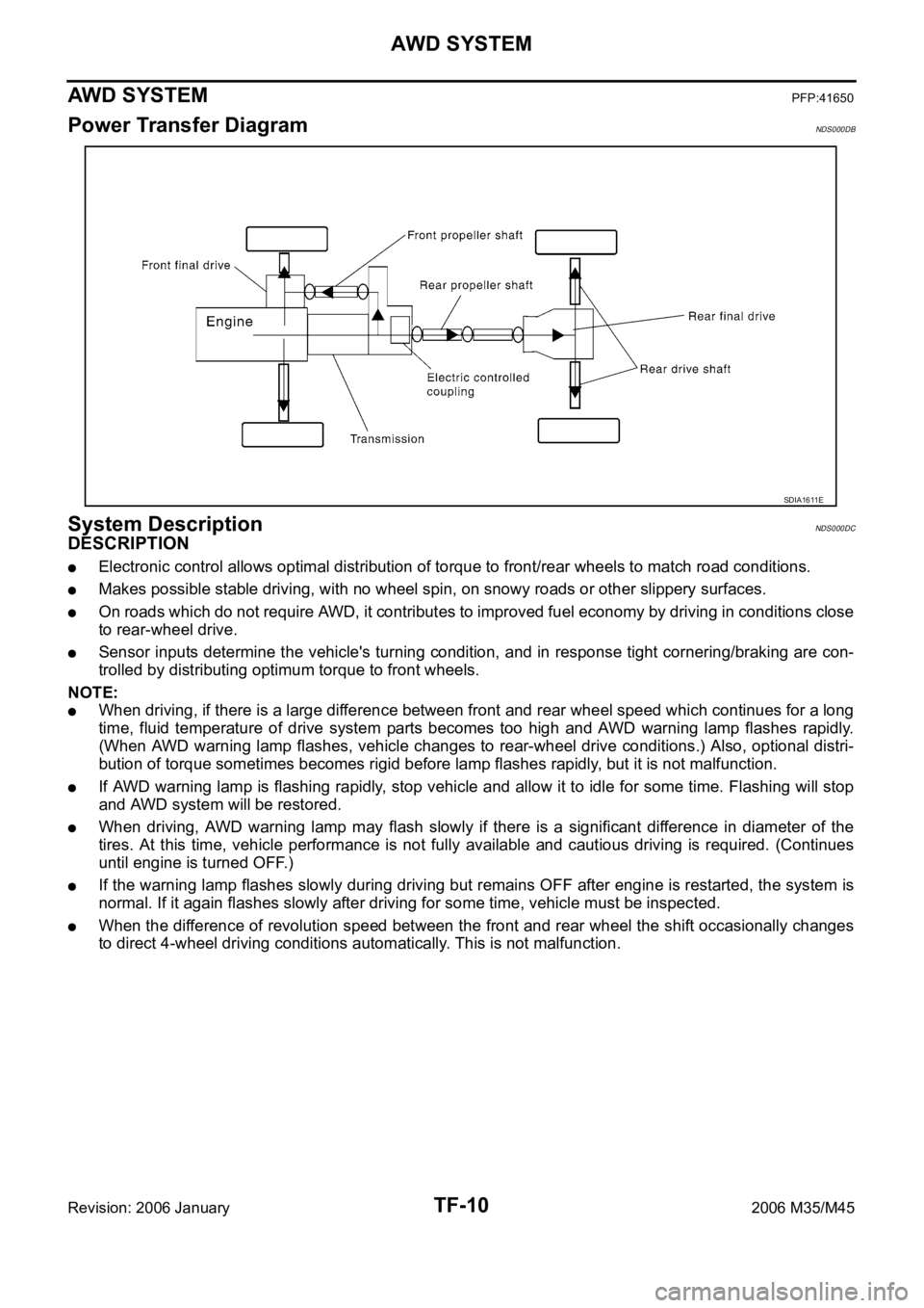
Power Transfer DiagramNDS000DB
System DescriptionNDS000DC
DESCRIPTION
Electronic control allows optimal distribution of torque to front/rear wheels to match road conditions.
Makes possible stable driving, with no wheel spin, on snowy roads or other slippery surfaces.
On roads which do not require AWD, it contributes to improved fuel economy by driving in conditions close
to rear-wheel drive.
Sensor inputs determine the vehicle's turning condition, and in response tight cornering/braking are con-
trolled by distributing optimum torque to front wheels.
NOTE:
When driving, if there is a large difference between front and rear wheel speed which continues for a long
time, fluid temperature of drive system parts becomes too high and AWD warning lamp flashes rapidly.
(When AWD warning lamp flashes, vehicle changes to rear-wheel drive conditions.) Also, optional distri-
bution of torque sometimes becomes rigid before lamp flashes rapidly, but it is not malfunction.
If AWD warning lamp is flashing rapidly, stop vehicle and allow it to idle for some time. Flashing will stop
and AWD system will be restored.
When driving, AWD warning lamp may flash slowly if there is a significant difference in diameter of the
tires. At this time, vehicle performance is not fully available and cautious driving is required. (Continues
until engine is turned OFF.)
If the warning lamp flashes slowly during driving but remains OFF after engine is restarted, the system is
normal. If it again flashes slowly after driving for some time, vehicle must be inspected.
When the difference of revolution speed between the front and rear wheel the shift occasionally changes
to direct 4-wheel driving conditions automatically. This is not malfunction.
SDIA1611E
Page 5476 of 5621

AWD SYSTEM
TF-11
C
E
F
G
H
I
J
K
L
MA
B
TF
Revision: 2006 January2006 M35/M45
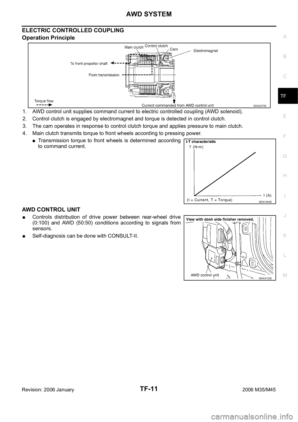
ELECTRIC CONTROLLED COUPLING
Operation Principle
1. AWD control unit supplies command current to electric controlled coupling (AWD solenoid).
2. Control clutch is engaged by electromagnet and torque is detected in control clutch.
3. The cam operates in response to control clutch torque and applies pressure to main clutch.
4. Main clutch transmits torque to front wheels according to pressing power.
Transmission torque to front wheels is determined according
to command current.
AWD CONTROL UNIT
Controls distribution of drive power between rear-wheel drive
(0:100) and AWD (50:50) conditions according to signals from
sensors.
Self-diagnosis can be done with CONSULT-II.
SDIA2270E
SDIA1844E
SDIA3133E
Page 5486 of 5621

TROUBLE DIAGNOSIS
TF-21
C
E
F
G
H
I
J
K
L
MA
B
TF
Revision: 2006 January2006 M35/M45
*1 : The values are changed by throttle opening and engine speed.
*2 : Mode switch is not equipped, but displayed.
CONSULT-II Function (ALL MODE AWD/4WD)NDS000DM
FUNCTION
CONSULT-II can display each diagnostic item using the diagnostic test modes shown following.
RR RH SENSOR [km/h] or [mph]Wheel speed (Rear wheel
right)Vehicle stopped 0.00 km/h (0.00 mph)
Vehicle running
CAUTION:
Check air pressure of tire under
standard condition.Approximately equal to
the indication on speed-
ometer (Inside of
10%)
RR LH SENSOR [km/h] or [mph]Wheel speed (Rear wheel
left)Vehicle stopped 0.00 km/h (0.00 mph)
Vehicle running
CAUTION:
Check air pressure of tire under
standard condition.Approximately equal to
the indication on speed-
ometer (Inside of
10%)
BATTERY VOLT [V]Power supply voltage for
AWD control unitIgnition switch: ON Battery voltage
THRTL POS SEN [%] Throttle opening conditionWhen depressing accelerator pedal
(Value rises gradually in response to
throttle position.)0 - 100%
ETS SOLENOID [A]Monitored value of current at
AWD solenoidEngine running
At idle speedApprox. 0.000A
Engine running
When depressing accelerator
pedalApprox. 0.000 - 0.500A*1
STOP LAMP SW [ON/OFF]Condition of brake pedal
operationBrake pedal: Depressed ON
Brake pedal: Released OFF
ENG SPEED SIG [RUN/STOP] Condition of engine runningEngine stopped
(Engine speed: Less than 400 rpm)STOP
Engine running
(Engine speed: 400 rpm or more)RUN
ETS ACTUATOR [ON/OFF]Operating condition of AWD
actuator relay (integrated in
AWD control unit)Engine stopped (Ignition
switch: ON)OFF
Engine running ON
4WD WARN LAMP [ON/OFF] AWD warning lamp conditionAWD warning lamp: ON ON
AWD warning lamp: OFF OFF
4WD MODE SW*
2 [AUTO]Input condition from mode
switchAlways AUTO
4WD MODE MON [AUTO] Control status of AWD Engine running AUTO
DIS-TIRE MONI [mm]Improper size tire installed
conditionVehicle running with normal size tire
installed0-4 mm
Vehicle running with improper size
tire installed (Front/rear tire size dif-
ference, wear condition)4-8 mm, 8- mm
P BRAKE SW [ON/OFF] Condition of parking brakeParking brake operated ON
Parking brake not operated OFF Monitor item [Unit] Content Condition Display value
Diagnostic test mode FunctionReference
page
Self-diagnostic results
Self-diagnostic results can be read and erased quickly.TF-22
Data monitorInput/Output data in the AWD control unit can be read.TF-24
Page 5538 of 5621

TROUBLE DIAGNOSES
WT-13
C
D
F
G
H
I
J
K
L
MA
B
WT
Revision: 2006 January2006 M35/M45
TROUBLE DIAGNOSESPFP:00004
How to Perform Trouble DiagnosesNES000JU
BASIC CONCEPT
The most important point to perform trouble diagnosis is to understand systems (control and mechanism)
in vehicle thoroughly.
It is also important to clarify customer complaints before inspec-
tion.
First of all, reproduce symptom, and understand it fully.
Ask customer about his/her complaints carefully. In some cases,
they will be necessary to check symptom by driving vehicle with
customer.
CAUTION:
Customers are not professionals. Do not assume “maybe
customer means...” or “maybe the customer mentioned this
symptom”.
It is essential to check symptoms right from beginning in order to
repair a malfunction completely.
For an intermittent malfunction, it is important to reproduce
symptom based on interview with customer and past examples.
Do not perform inspection on ad hoc basis. Most intermittent
malfunctions are caused by poor contacts. In this case, it will be
effective to shake suspected harness or connector by hand.
When repairs are performed without any symptom check, no
one can judge if malfunction has actually been eliminated.
Always diagnosis, make sure to perform “ERASE MEMORY”.
Always read “GI General information” to confirm general precau-
tions. Refer to GI-4, "
General Precautions" .
EFJ0028D
SEF233G
Page 5546 of 5621
![INFINITI M35 2006 Factory Service Manual TROUBLE DIAGNOSES
WT-21
C
D
F
G
H
I
J
K
L
MA
B
WT
Revision: 2006 January2006 M35/M45
Transmitter Wake Up OperationNES000JZ
WITH TRANSMITTER ACTIVATION TOOL
1. With the activation tool [SST: J-45295] p INFINITI M35 2006 Factory Service Manual TROUBLE DIAGNOSES
WT-21
C
D
F
G
H
I
J
K
L
MA
B
WT
Revision: 2006 January2006 M35/M45
Transmitter Wake Up OperationNES000JZ
WITH TRANSMITTER ACTIVATION TOOL
1. With the activation tool [SST: J-45295] p](/img/42/57023/w960_57023-5545.png)
TROUBLE DIAGNOSES
WT-21
C
D
F
G
H
I
J
K
L
MA
B
WT
Revision: 2006 January2006 M35/M45
Transmitter Wake Up OperationNES000JZ
WITH TRANSMITTER ACTIVATION TOOL
1. With the activation tool [SST: J-45295] pushed against the front-
left transmitter, press and hold the button for 5 seconds.
When ignition switch ON, as the low tire pressure warning
lamp blinks per the follow diagram, the respective transmitter
then must be woken up.
2. Register the ID of wheel that warning lamp flashes. When wake up of registered wheel has been com-
pleted, turn signal lamp flashes two times.
3. After completing wake up all transmitters, make sure low tire pressure warning lamp goes out.
CONSULT-II Function (AIR PRESSURE MONITOR)NES000K0
FUNCTION
CONSULT-II can display each diagnosis item using the diagnosis test modes shown following.
CONSULT-II SETTING PROCEDURE
Refer to GI-39, "CONSULT-II Start Procedure" .
SEIA0460E
SEIA0378E
Mode Function Reference
WORK SUPPORTThis mode enables a technician to adjust some devices faster and
more accurately by following the indications on CONSULT-II.WT-22, "
WORK SUP-
PORT MODE"
SELF-DIAG RESULTSReceives self-diagnosis results from low tire pressure warning con-
trol unit and indicates DTCs. WT-22, "SELF-DIAG
RESULT MODE"
DATA MONITORReceives input/output signals from low tire pressure warning control
unit and indicates and stores them to facilitate locating cause of mal-
functions.WT-23, "DATA MONITOR
MODE"
CAN DIAG SUPPORT MNTR Monitors transmitting/receiving status of CAN communication.WT-12, "CAN COMMUNI-
CATION"
ACTIVE TESTDiagnostic Test Mode in with CONSULT-II drives some actuators
apart from the low tire pressure warning control unit and also shifts
some parameters in a specified range.WT-23, "ACTIVE TEST
MODE"
ECU PART NUMBER Displays low tire pressure warning control unit part number. WT-24, "
LOW TIRE PRES-
SURE WARNING CON-
TROL UNIT PART
NUMBER"
Page 5575 of 5621

WW-8
FRONT WIPER AND WASHER SYSTEM
Revision: 2006 January2006 M35/M45
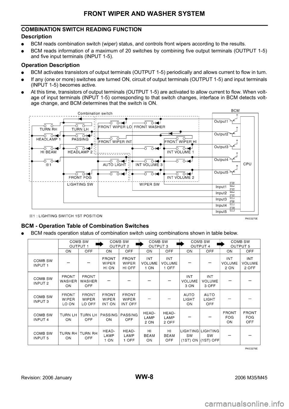
COMBINATION SWITCH READING FUNCTION
Description
BCM reads combination switch (wiper) status, and controls front wipers according to the results.
BCM reads information of a maximum of 20 switches by combining five output terminals (OUTPUT 1-5)
and five input terminals (INPUT 1-5).
Operation Description
BCM activates transistors of output terminals (OUTPUT 1-5) periodically and allows current to flow in turn.
If any (one or more) switches are turned ON, circuit of output terminals (OUTPUT 1-5) and input terminals
(INPUT 1-5) becomes active.
At this time, transistors of output terminals (OUTPUT 1-5) are activated to allow current to flow. When volt-
age of input terminals (INPUT 1-5) corresponding to that switch changes, interface in BCM detects volt-
age change, and BCM determines that the switch is ON.
BCM - Operation Table of Combination Switches
BCM reads operation status of combination switch using combinations shown in table below.
PKIC0270E
PKIC0276E