height adjustment INFINITI M35 2006 Factory Service Manual
[x] Cancel search | Manufacturer: INFINITI, Model Year: 2006, Model line: M35, Model: INFINITI M35 2006Pages: 5621, PDF Size: 65.56 MB
Page 10 of 5621
ACS-1
AUTO CRUISE CONTROL SYSTEM
K ELECTRICAL
CONTENTS
C
D
E
F
G
H
I
J
L
M
SECTION ACS
A
B
ACS
Revision: 2006 January2006 M35/M45
AUTO CRUISE CONTROL SYSTEM
ASCD
AUTOMATIC SPEED CONTROL DEVICE (ASCD) ..... 3
Description ............................................................... 3
ICC
PRECAUTIONS .......................................................... 4
Precautions for Supplemental Restraint System
(SRS) “AIR BAG” and “SEAT BELT PRE-TEN-
SIONER” .................................................................. 4
Precautions for ICC System Service ........................ 4
PREPARATION ........................................................... 5
Special Service Tools ............................................... 5
DESCRIPTION ............................................................ 6
Outline ...................................................................... 6
VEHICLE-TO-VEHICLE DISTANCE CONTROL
MODE ................................................................... 6
CONVENTIONAL (FIXED SPEED) CRUISE
CONTROL MODE ................................................. 6
BRAKE ASSIST (WITH PREVIEW FUNCTION) ..... 6
System Diagram ....................................................... 6
Components Description .......................................... 7
CAN Communication ................................................ 7
CAN COMMUNICATION UNIT ............................. 7
Switch Operation ...................................................... 8
IN VEHICLE-TO-VEHICLE DISTANCE CON-
TROL MODE ......................................................... 8
IN CONVENTIONAL (FIXED SPEED) CRUISE
CONTROL MODE ................................................. 8
ICC System Display ................................................. 9
IN VEHICLE-TO-VEHICLE DISTANCE CON-
TROL MODE ......................................................... 9
IN CONVENTIONAL (FIXED SPEED) CRUISE
CONTROL MODE ................................................. 9
ACTION TEST .......................................................... 10
ICC System Running Test ...................................... 10
VEHICLE-TO-VEHICLE DISTANCE CONTROL
MODE ................................................................. 10
CONVENTIONAL (FIXED SPEED) CRUISE
CONTROL MODE ................................................ 11LASER BEAM AIMING ADJUSTMENT ................... 13
Outline .................................................................... 13
Preparation ............................................................. 13
Outline of Adjustment Procedure ............................ 13
Setting the ICC Target Board .................................. 13
ADJUSTING HEIGHT OF THE TARGET ............ 13
ADJUSTING THE RIGHT-LEFT POSITION OF
THE TARGET ...................................................... 14
SETTING THE TARGET ..................................... 14
Aiming Adjustment .................................................. 16
CHECK AFTER THE ADJUSTMENT .................. 18
ELECTRICAL UNITS LOCATION ............................ 19
Component Parts and Harness Connector Location ... 19
WIRING DIAGRAM ................................................... 20
Schematic ............................................................... 20
Wiring Diagram — ICC — ...................................... 21
TERMINALS AND REFERENCE VALUE ................. 26
Terminals and Reference Value for ICC Sensor Inte-
grated Unit .............................................................. 26
TROUBLE DIAGNOSIS - GENERAL DESCRIP-
TION .......................................................................
... 27
Fail-Safe Function .................................................. 27
Work Flow ............................................................... 27
CONSULT-II Function (ICC) ................................... 28
DESCRIPTION .................................................... 28
CONSULT-II BASIC OPERATION ....................... 28
WORK SUPPORT ............................................... 29
SELF-DIAGNOSTIC RESULTS ........................... 30
DATA MONITOR ................................................. 30
ACTIVE TEST ..................................................... 33
Self-Diagnostic Function ......................................... 34
WITH CONSULT-II .............................................. 34
WITHOUT CONSULT-II ....................................... 34
SELF-DIAGNOSIS BY DOT MATRIX LCD WILL
NOT RUN ............................................................ 36
TROUBLE DIAGNOSIS FOR SELF-DIAGNOSTIC
ITEMS ........................................................................ 39
Diagnostic Trouble Code (DTC) Chart ................... 39
DTC 0 CONTROL UNIT ......................................... 41
DTC 1 POWER SUPPLY CIR, DTC 2 POWER SUP-
Page 22 of 5621
![INFINITI M35 2006 Factory Service Manual LASER BEAM AIMING ADJUSTMENT
ACS-13
[ICC]
C
D
E
F
G
H
I
J
L
MA
B
ACS
Revision: 2006 January2006 M35/M45
LASER BEAM AIMING ADJUSTMENTPFP:00026
OutlineNKS004CM
Adjust the laser beam aiming every time th INFINITI M35 2006 Factory Service Manual LASER BEAM AIMING ADJUSTMENT
ACS-13
[ICC]
C
D
E
F
G
H
I
J
L
MA
B
ACS
Revision: 2006 January2006 M35/M45
LASER BEAM AIMING ADJUSTMENTPFP:00026
OutlineNKS004CM
Adjust the laser beam aiming every time th](/img/42/57023/w960_57023-21.png)
LASER BEAM AIMING ADJUSTMENT
ACS-13
[ICC]
C
D
E
F
G
H
I
J
L
MA
B
ACS
Revision: 2006 January2006 M35/M45
LASER BEAM AIMING ADJUSTMENTPFP:00026
OutlineNKS004CM
Adjust the laser beam aiming every time the ICC sensor integrated unit is removed or installed.
CAUTION:
Adjust laser beam aiming at a horizontal place as far as 12 m (39 ft) forward the vehicle can be
seen.
Adjust laser beam aiming 5 seconds after starting engine.
Never view ICC sensor integrated unit body window directly during laser beam aiming adjustment.
Follow the CONSULT-II when adjusting the laser beam aiming (laser beam aiming adjustment can-
not be operated without CONSULT-II).
Never ride on vehicle during laser beam aiming adjustment.
Idle and turn headlamps OFF during laser beam aiming adjustment.
PreparationNKS004CN
Adjust the tire pressure to the specified value.
See that there is no load in the vehicle.
Coolant, engine oil filled up to correct level and full fuel tank.
Shift the gear into “P” position and release the parking brake.
Clean the ICC sensor integrated unit with a soft cloth.
Remove the front bumper grille. Refer to EI-13, "Removal and
Installation of Front Bumper Grille" .
Outline of Adjustment ProcedureNKS004CO
1. Set up the ICC target board [KV99110100 (J-45718)].
2. Adjust the sensor following the procedure on CONSULT-II. (Turn manually the screw for up-down position
adjustment. ICC sensor integrated unit automatically adjust the right-left position.)
Setting the ICC Target BoardNKS004CP
Accurate ICC target board setting is required for the laser beam aiming adjustment.
CAUTION:
ICC system does not function normally if laser beam aiming is not accurate.
ADJUSTING HEIGHT OF THE TARGET
1. Attach a triangle scale at 28 mm (1.10 in) below the center.
PKIB8350E
PKIB8351E
Page 23 of 5621
![INFINITI M35 2006 Factory Service Manual ACS-14
[ICC]
LASER BEAM AIMING ADJUSTMENT
Revision: 2006 January2006 M35/M45
2. Adjust the height of the target board with aligning the upside tip
of the triangle scale with the center of laser beam a INFINITI M35 2006 Factory Service Manual ACS-14
[ICC]
LASER BEAM AIMING ADJUSTMENT
Revision: 2006 January2006 M35/M45
2. Adjust the height of the target board with aligning the upside tip
of the triangle scale with the center of laser beam a](/img/42/57023/w960_57023-22.png)
ACS-14
[ICC]
LASER BEAM AIMING ADJUSTMENT
Revision: 2006 January2006 M35/M45
2. Adjust the height of the target board with aligning the upside tip
of the triangle scale with the center of laser beam axis.
NOTE:
The center of laser beam axis is located at 92 mm (3.62 in) from
the right edge and 22 mm (0.87 in) from the top of the ICC sen-
sor integrated unit from a front view of vehicle.
ADJUSTING THE RIGHT-LEFT POSITION OF THE TARGET
1. Attach a scale [at least 350 mm (14 in) or longer] or stick as
shown in the figure.
2. Suspend a thread with weight on the tip of the thread to 266 mm
(10.47 in) right side of the target board from the center of the
target board on top.
SETTING THE TARGET
1. Suspend a thread with weight on tip to splice the center of the front and rear bumpers. Then, mark the
center point on the ground as each weight points.
2. Link the front and rear bumpers center points marked on the ground, and mark a point 3.9 m (12.8 ft)
ahead of the front bumper, on the extended line of the previous link line of the bumper center points.
Then, adjust the position of the target board so that the weight come on the top of the marked point [3.9 m
(12.8 ft) ahead of the front bumper] and face to the vehicle.
PKIB4486J
PKIB8352E
PKIB8353E
PKIB8354E
Page 955 of 5621
BL-16
HOOD
Revision: 2006 January2006 M35/M45
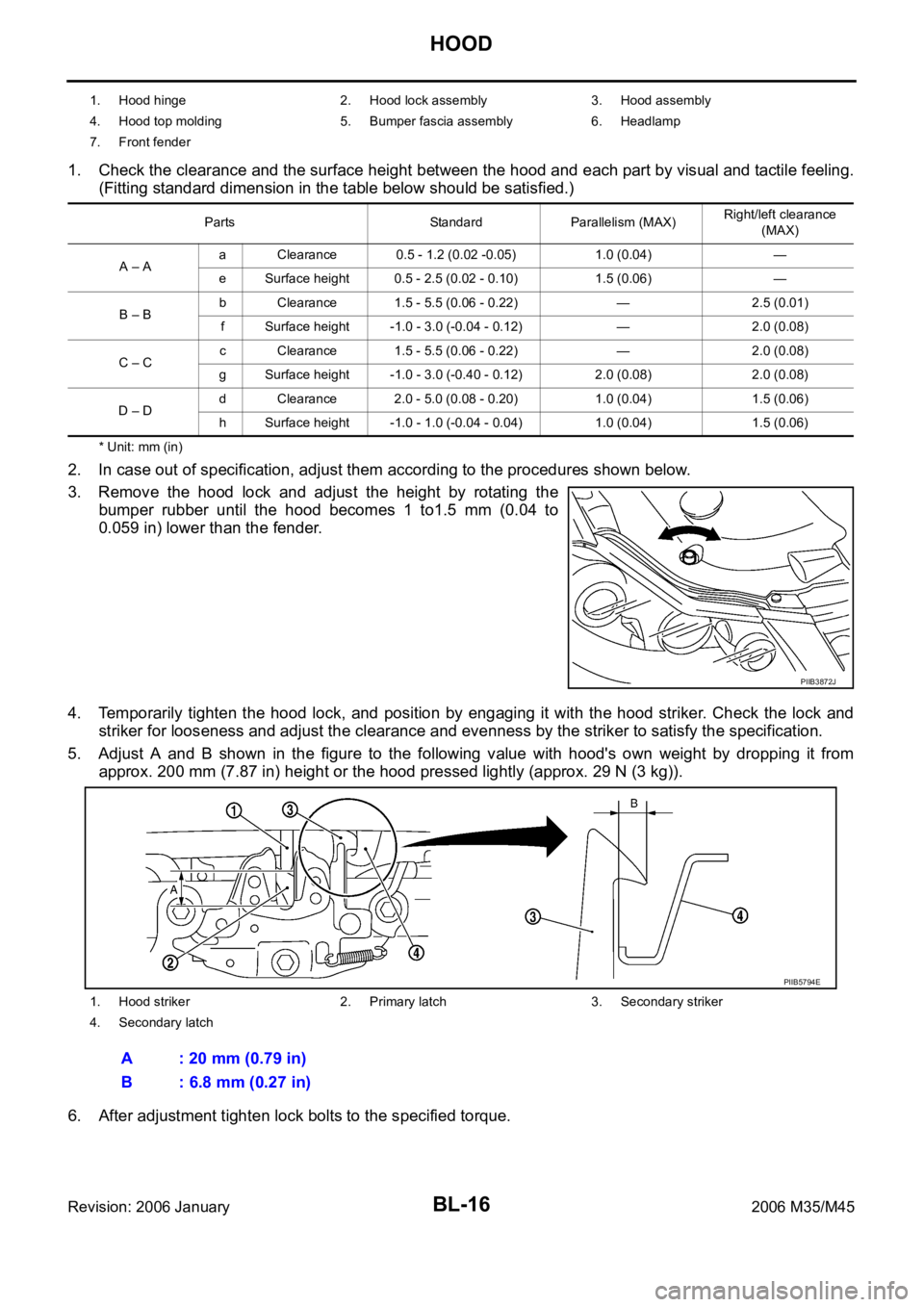
1. Check the clearance and the surface height between the hood and each part by visual and tactile feeling.
(Fitting standard dimension in the table below should be satisfied.)
* Unit: mm (in)
2. In case out of specification, adjust them according to the procedures shown below.
3. Remove the hood lock and adjust the height by rotating the
bumper rubber until the hood becomes 1 to1.5 mm (0.04 to
0.059 in) lower than the fender.
4. Temporarily tighten the hood lock, and position by engaging it with the hood striker. Check the lock and
striker for looseness and adjust the clearance and evenness by the striker to satisfy the specification.
5. Adjust A and B shown in the figure to the following value with hood's own weight by dropping it from
approx. 200 mm (7.87 in) height or the hood pressed lightly (approx. 29 N (3 kg)).
6. After adjustment tighten lock bolts to the specified torque.
1. Hood hinge 2. Hood lock assembly 3. Hood assembly
4. Hood top molding 5. Bumper fascia assembly 6. Headlamp
7. Front fender
Parts Standard Parallelism (MAX)Right/left clearance
(MAX)
A – Aa Clearance 0.5 - 1.2 (0.02 -0.05) 1.0 (0.04) —
e Surface height 0.5 - 2.5 (0.02 - 0.10) 1.5 (0.06) —
B – Bb Clearance 1.5 - 5.5 (0.06 - 0.22) — 2.5 (0.01)
f Surface height -1.0 - 3.0 (-0.04 - 0.12) — 2.0 (0.08)
C – Cc Clearance 1.5 - 5.5 (0.06 - 0.22) — 2.0 (0.08)
g Surface height -1.0 - 3.0 (-0.40 - 0.12) 2.0 (0.08) 2.0 (0.08)
D – Dd Clearance 2.0 - 5.0 (0.08 - 0.20) 1.0 (0.04) 1.5 (0.06)
h Surface height -1.0 - 1.0 (-0.04 - 0.04) 1.0 (0.04) 1.5 (0.06)
PIIB3872J
1. Hood striker 2. Primary latch 3. Secondary striker
4. Secondary latch
A : 20 mm (0.79 in)
B : 6.8 mm (0.27 in)
PIIB5794E
Page 1129 of 5621
BL-190
DOOR
Revision: 2006 January2006 M35/M45
DOORPFP:80100
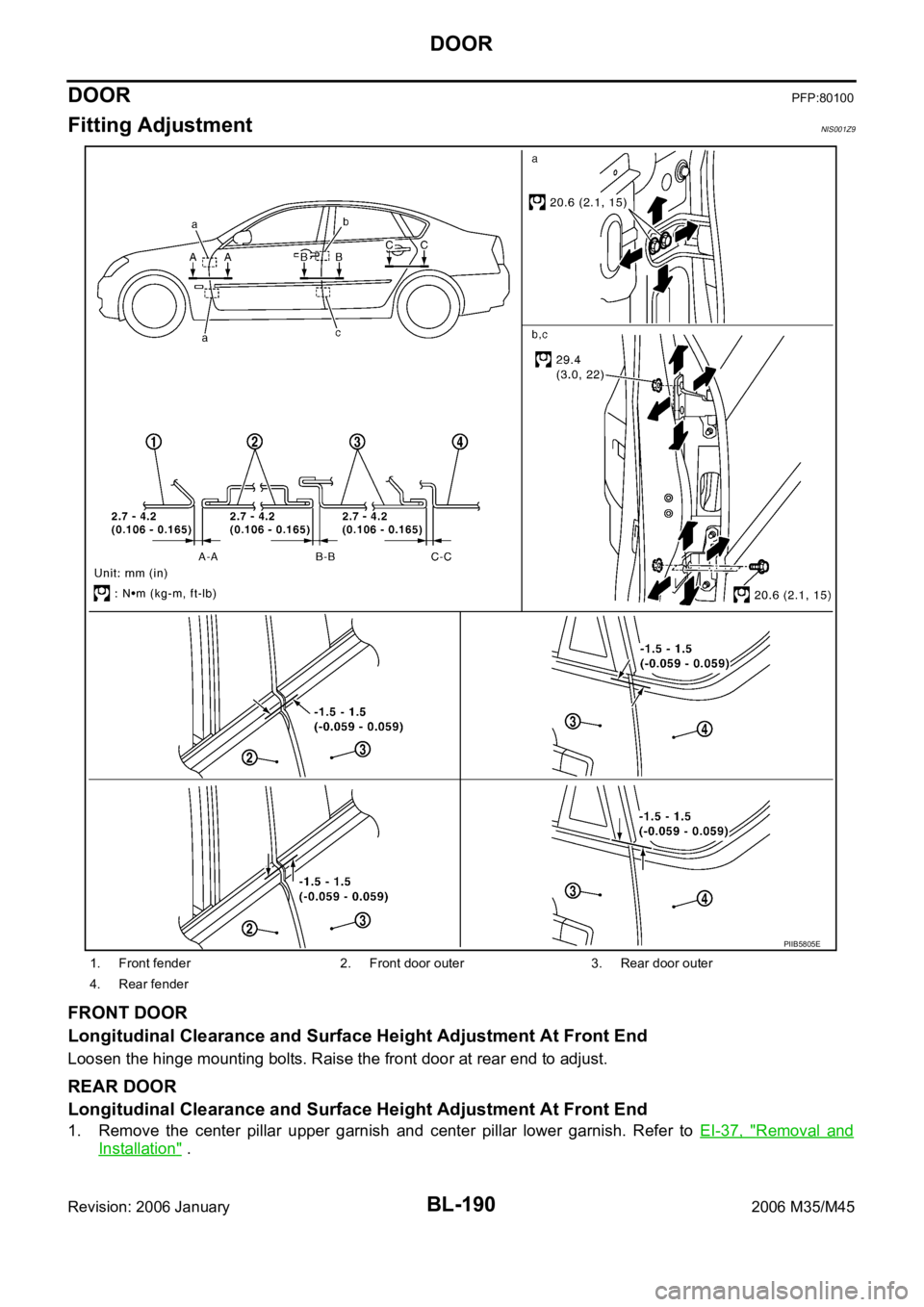
Fitting AdjustmentNIS001Z9
FRONT DOOR
Longitudinal Clearance and Surface Height Adjustment At Front End
Loosen the hinge mounting bolts. Raise the front door at rear end to adjust.
REAR DOOR
Longitudinal Clearance and Surface Height Adjustment At Front End
1. Remove the center pillar upper garnish and center pillar lower garnish. Refer to EI-37, "Removal and
Installation" .
1. Front fender 2. Front door outer 3. Rear door outer
4. Rear fender
PIIB5805E
Page 1143 of 5621
BL-204
TRUNK LID
Revision: 2006 January2006 M35/M45
Loosen the striker mounting bolts.
Lift up the trunk lid approx. 100 - 150 mm (3.94 - 5.91 in) height then close it lightly and make sure it
engaged firmly with the trunk lid closed.
Check the clearance and evenness.
Finally tighten the trunk lid striker.
Removal and Installation of Trunk Lid AssemblyNIS001ZI
CAUTION:
After installing, apply touch-up paint (the body color) onto the head of the hinge mounting bolts.
After installing, check operation.
After installing, perform fitting adjustment. Refer to BL-203, "Fitting Adjustment" .
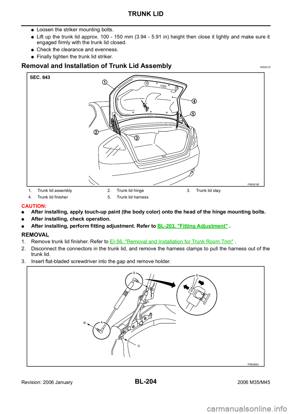
REMOVAL
1. Remove trunk lid finisher. Refer to EI-56, "Removal and Installation for Trunk Room Trim" .
2. Disconnect the connectors in the trunk lid, and remove the harness clamps to pull the harness out of the
trunk lid.
3. Insert flat-bladed screwdriver into the gap and remove holder.
1. Trunk lid assembly 2. Trunk lid hinge 3. Trunk lid stay
4. Trunk lid finisher 5. Trunk lid harness
PIIB5818E
PIIB3895J
Page 1145 of 5621
BL-206
TRUNK LID
Revision: 2006 January2006 M35/M45
Removal and Installation of Trunk Lid LockNIS001ZK
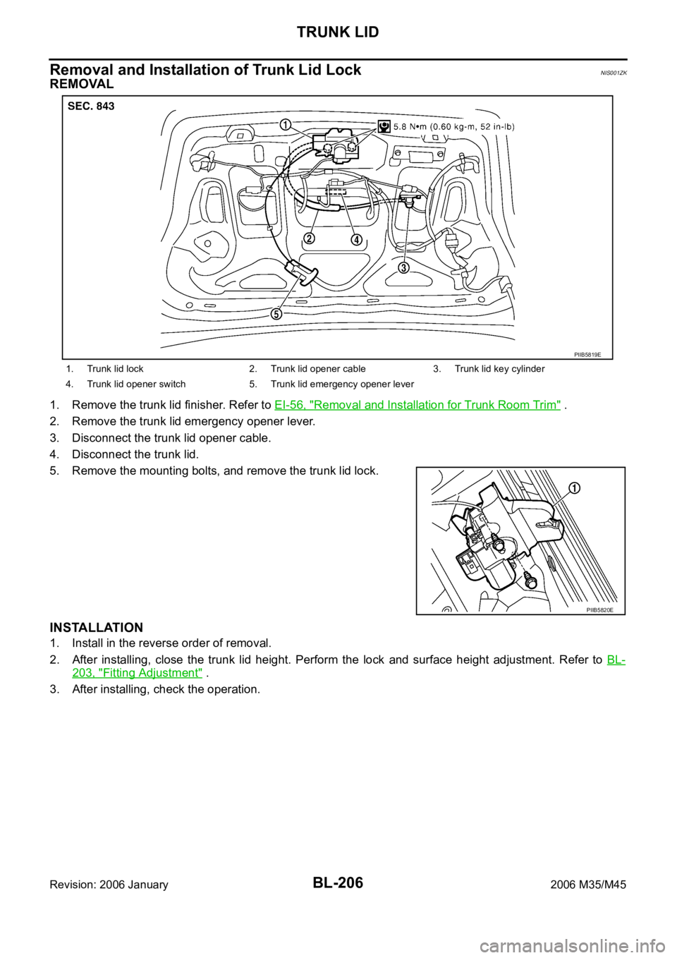
REMOVAL
1. Remove the trunk lid finisher. Refer to EI-56, "Removal and Installation for Trunk Room Trim" .
2. Remove the trunk lid emergency opener lever.
3. Disconnect the trunk lid opener cable.
4. Disconnect the trunk lid.
5. Remove the mounting bolts, and remove the trunk lid lock.
INSTALLATION
1. Install in the reverse order of removal.
2. After installing, close the trunk lid height. Perform the lock and surface height adjustment. Refer to BL-
203, "Fitting Adjustment" .
3. After installing, check the operation.
1. Trunk lid lock 2. Trunk lid opener cable 3. Trunk lid key cylinder
4. Trunk lid opener switch 5. Trunk lid emergency opener lever
PIIB5819E
PIIB5820E
Page 1146 of 5621
TRUNK LID
BL-207
C
D
E
F
G
H
J
K
L
MA
B
BL
Revision: 2006 January2006 M35/M45
Removal and Installation of Trunk Lid StrikerNIS001ZL
REMOVAL
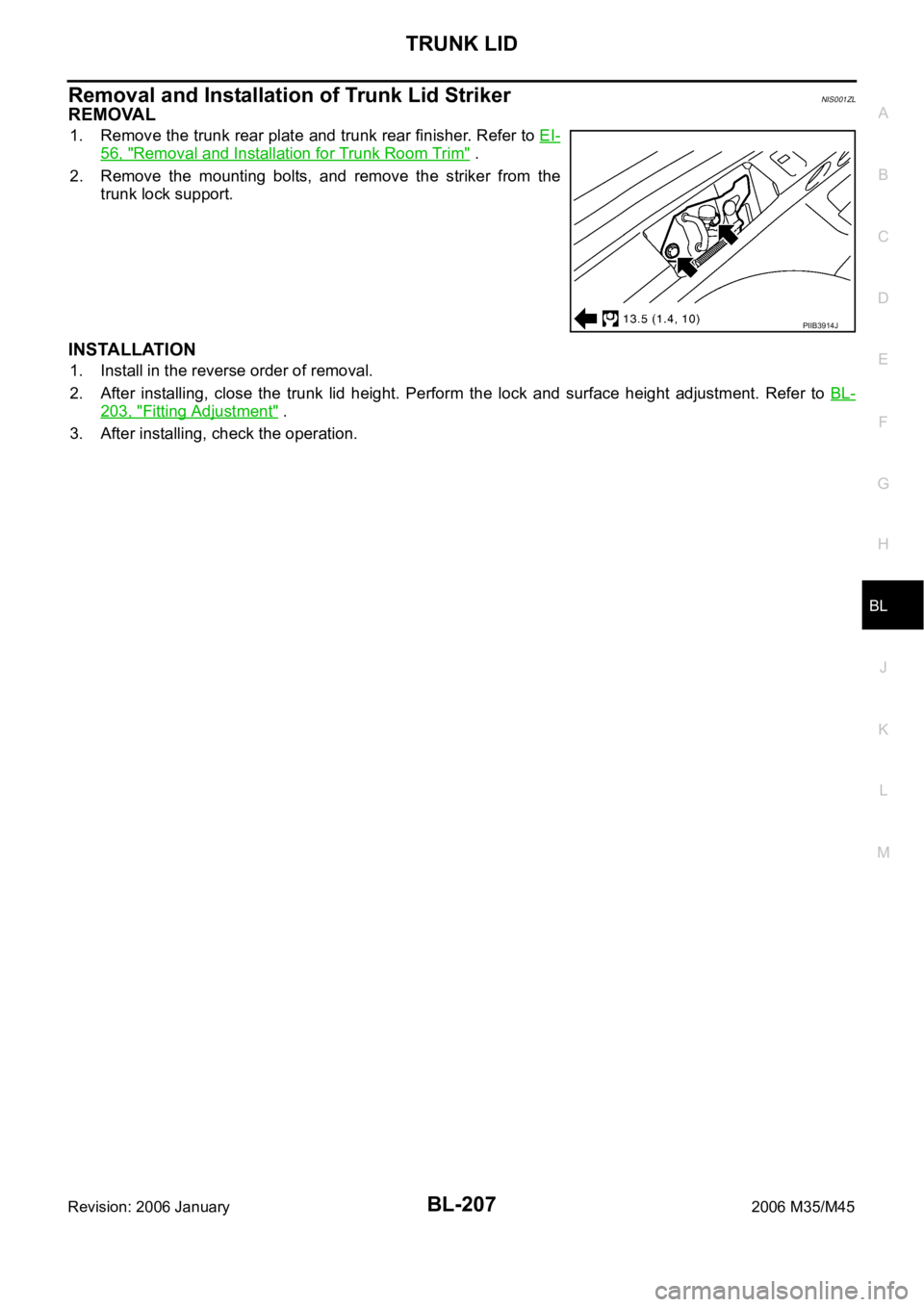
1. Remove the trunk rear plate and trunk rear finisher. Refer to EI-
56, "Removal and Installation for Trunk Room Trim" .
2. Remove the mounting bolts, and remove the striker from the
trunk lock support.
INSTALLATION
1. Install in the reverse order of removal.
2. After installing, close the trunk lid height. Perform the lock and surface height adjustment. Refer to BL-
203, "Fitting Adjustment" .
3. After installing, check the operation.
PIIB3914J
Page 1281 of 5621
BR-6
BRAKE PEDAL
Revision: 2006 January2006 M35/M45
BRAKE PEDALPFP:46501
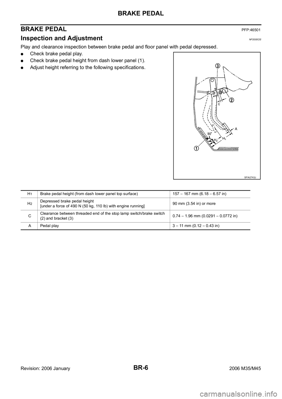
Inspection and AdjustmentNFS000OS
Play and clearance inspection between brake pedal and floor panel with pedal depressed.
Check brake pedal play.
Check brake pedal height from dash lower panel (1).
Adjust height referring to the following specifications.
SFIA2743J
H1Brake pedal height (from dash lower panel top surface) 157 167 mm (6.18 6.57 in)
H
2Depressed brake pedal height
[under a force of 490 N (50 kg, 110 lb) with engine running]90 mm (3.54 in) or more
CClearance between threaded end of the stop lamp switch/brake switch
(2) and bracket (3)0.74
1.96 mm (0.0291 0.0772 in)
A Pedal play 3
11 mm (0.12 0.43 in)
Page 1282 of 5621
BRAKE PEDAL
BR-7
C
D
E
G
H
I
J
K
L
MA
B
BR
Revision: 2006 January2006 M35/M45
ADJUSTMENT
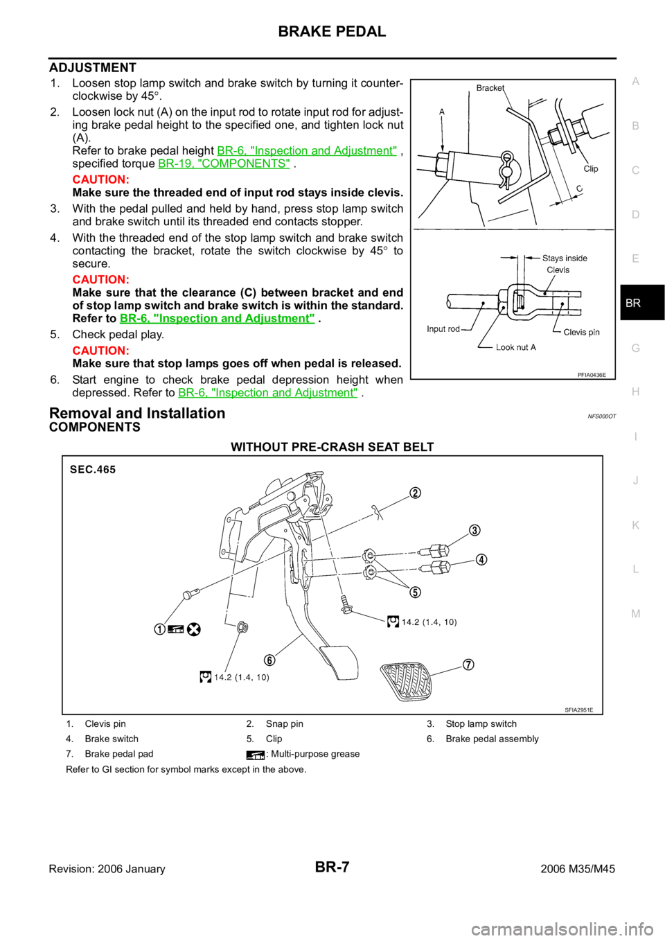
1. Loosen stop lamp switch and brake switch by turning it counter-
clockwise by 45
.
2. Loosen lock nut (A) on the input rod to rotate input rod for adjust-
ing brake pedal height to the specified one, and tighten lock nut
(A).
Refer to brake pedal height BR-6, "
Inspection and Adjustment" ,
specified torque BR-19, "
COMPONENTS" .
CAUTION:
Make sure the threaded end of input rod stays inside clevis.
3. With the pedal pulled and held by hand, press stop lamp switch
and brake switch until its threaded end contacts stopper.
4. With the threaded end of the stop lamp switch and brake switch
contacting the bracket, rotate the switch clockwise by 45
to
secure.
CAUTION:
Make sure that the clearance (C) between bracket and end
of stop lamp switch and brake switch is within the standard.
Refer to BR-6, "
Inspection and Adjustment" .
5. Check pedal play.
CAUTION:
Make sure that stop lamps goes off when pedal is released.
6. Start engine to check brake pedal depression height when
depressed. Refer to BR-6, "
Inspection and Adjustment" .
Removal and InstallationNFS000OT
COMPONENTS
WITHOUT PRE-CRASH SEAT BELT
PFIA0436E
SFIA2951E
1. Clevis pin 2. Snap pin 3. Stop lamp switch
4. Brake switch 5. Clip 6. Brake pedal assembly
7. Brake pedal pad : Multi-purpose grease
Refer to GI section for symbol marks except in the above.