Shift INFINITI M35 2006 Factory Service Manual
[x] Cancel search | Manufacturer: INFINITI, Model Year: 2006, Model line: M35, Model: INFINITI M35 2006Pages: 5621, PDF Size: 65.56 MB
Page 5401 of 5621

SRS-40
SPIRAL CABLE
Revision: 2006 January2006 M35/M45
SPIRAL CABLEPFP:25554
Removal and InstallationNHS0009D
REMOVAL
CAUTION:
Before servicing, turn ignition switch OFF, disconnect both battery terminal and wait at least 3
minutes.
Do not use air tools or electric tools for servicing.
Do not disassemble the spiral cable.
Do not arrow oil, grease, detergent or water to come in contact with the spiral cable.
Do not make an impact to the spiral cable by dropping etc. Replace the spiral cable if it has been
dropped or sustained an impact.
1. Remove the air bag module. Refer to SRS-38, "
Removal and Installation" .
2. Remove the steering wheel. Refer to PS-12, "
Removal and Installation" .
3. Remove the column cover.
4. Remove the wiper washer switch, then remove light and turn signal switch from the spiral cable.
5. Remove the spiral cable.
Disconnect the horn switch connector (shown as A in the fig-
ure).
Disconnect the spiral cable connector (shown as B in the fig-
ure).
Loosen the spiral cable fixing screws.
Shift the spiral cable forward a bit while pushing the pawl
located above the spiral cable.
Disconnect the steering wheel switch connector (shown as C
in the figure).
NOTE:
Disconnect the spiral cable connector after disconnecting the
horn switch connector.
INSTALLATION
Install in the reverse order of removal.
PHIA1112E
1. Steering wheel 2. Steering column cover (lower) 3. Light and turn signalswitchs
4. Wiper washer switch 5. Spiral cable 6. Steering column cover (upper)
7. Steering column assembly 8. Driver air bag module connector
PHIA0886J
Page 5475 of 5621

TF-10
AWD SYSTEM
Revision: 2006 January2006 M35/M45
AWD SYSTEMPFP:41650
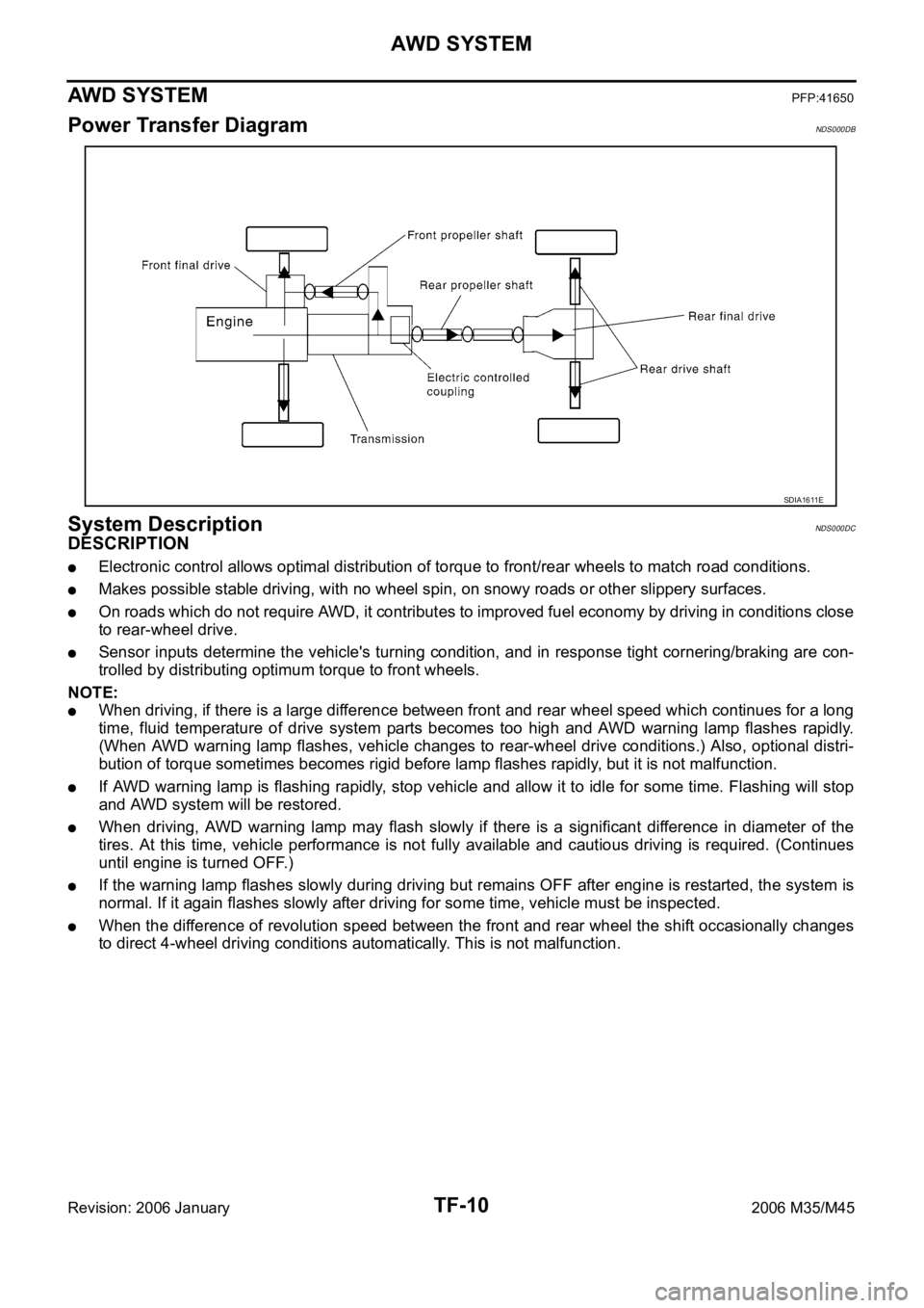
Power Transfer DiagramNDS000DB
System DescriptionNDS000DC
DESCRIPTION
Electronic control allows optimal distribution of torque to front/rear wheels to match road conditions.
Makes possible stable driving, with no wheel spin, on snowy roads or other slippery surfaces.
On roads which do not require AWD, it contributes to improved fuel economy by driving in conditions close
to rear-wheel drive.
Sensor inputs determine the vehicle's turning condition, and in response tight cornering/braking are con-
trolled by distributing optimum torque to front wheels.
NOTE:
When driving, if there is a large difference between front and rear wheel speed which continues for a long
time, fluid temperature of drive system parts becomes too high and AWD warning lamp flashes rapidly.
(When AWD warning lamp flashes, vehicle changes to rear-wheel drive conditions.) Also, optional distri-
bution of torque sometimes becomes rigid before lamp flashes rapidly, but it is not malfunction.
If AWD warning lamp is flashing rapidly, stop vehicle and allow it to idle for some time. Flashing will stop
and AWD system will be restored.
When driving, AWD warning lamp may flash slowly if there is a significant difference in diameter of the
tires. At this time, vehicle performance is not fully available and cautious driving is required. (Continues
until engine is turned OFF.)
If the warning lamp flashes slowly during driving but remains OFF after engine is restarted, the system is
normal. If it again flashes slowly after driving for some time, vehicle must be inspected.
When the difference of revolution speed between the front and rear wheel the shift occasionally changes
to direct 4-wheel driving conditions automatically. This is not malfunction.
SDIA1611E
Page 5477 of 5621

TF-12
AWD SYSTEM
Revision: 2006 January2006 M35/M45
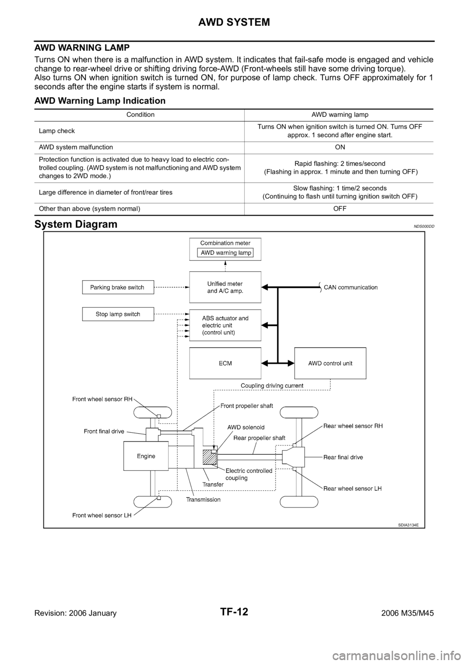
AWD WARNING LAMP
Turns ON when there is a malfunction in AWD system. It indicates that fail-safe mode is engaged and vehicle
change to rear-wheel drive or shifting driving force-AWD (Front-wheels still have some driving torque).
Also turns ON when ignition switch is turned ON, for purpose of lamp check. Turns OFF approximately for 1
seconds after the engine starts if system is normal.
AWD Warning Lamp Indication
System DiagramNDS000DD
Condition AWD warning lamp
Lamp checkTurns ON when ignition switch is turned ON. Turns OFF
approx. 1 second after engine start.
AWD system malfunctionON
Protection function is activated due to heavy load to electric con-
trolled coupling. (AWD system is not malfunctioning and AWD system
changes to 2WD mode.)Rapid flashing: 2 times/second
(Flashing in approx. 1 minute and then turning OFF)
Large difference in diameter of front/rear tiresSlow flashing: 1 time/2 seconds
(Continuing to flash until turning ignition switch OFF)
Other than above (system normal) OFF
SDIA3134E
Page 5479 of 5621

TF-14
TROUBLE DIAGNOSIS
Revision: 2006 January2006 M35/M45
TROUBLE DIAGNOSISPFP:00004
Fail-Safe FunctionNDS000DF
If any malfunction occurs in AWD electrical system, and control unit detects the malfunction, AWD warn-
ing lamp on combination meter turns ON to indicate system malfunction.
When AWD warning lamp is ON, vehicle changes to rear-wheel drive or shifting driving force-AWD (Front-
wheels still have some driving torque).
How to Perform Trouble DiagnosisNDS000DG
BASIC CONCEPT
To perform trouble diagnosis, it is the most important to have understanding about vehicle systems (con-
trol and mechanism) thoroughly.
It is also important to clarify customer complaints before inspec-
tion.
First of all, reproduce symptoms, and understand them fully.
Ask customer about his/her complaints carefully. In some cases,
it will be necessary to check symptoms by driving vehicle with
customer.
CAUTION:
Customers are not professional. It is dangerous to make an
easy guess like “maybe the customer means that...,” or
“maybe the customer mentions this symptom”.
It is essential to check symptoms right from the beginning in
order to repair malfunctions completely.
For intermittent malfunctions, reproduce symptoms based on
interview with customer and past examples. Do not perform
inspection on ad hoc basis. Most intermittent malfunctions are
caused by poor contacts. In this case, it will be effective to shake
suspected harness or connector by hand. When repairing with-
out any symptom diagnosis, you cannot judge if malfunctions
have actually been eliminated.
After completing diagnosis, always erase diagnostic memory.
Refer to TF-22, "
How to Erase Self-Diagnostic Results" .
For intermittent malfunctions, move harness or harness connec-
tor by hand. Then check for poor contact or reproduced open circuit.
SEF233G
SEF234G
Page 5487 of 5621

TF-22
TROUBLE DIAGNOSIS
Revision: 2006 January2006 M35/M45
CONSULT-II SETTING PROCEDURE
Refer to GI-39, "CONSULT-II Start Procedure" .
SELF-DIAG RESULT MODE
Operation Procedure
1. Perform “CONSULT-II Start Procedure”. Refer to GI-39, "CONSULT-II Start Procedure" .
2. Start engine and drive at 30 km/h (19 MPH) or more for approx. 1 minute.
3. Stop vehicle. With engine at idle, touch “SELF-DIAG RESULTS”.
Display shows malfunction experienced since the last erasing
operation.
NOTE:
The details for “TIME” are as follow:
–“0”: Error currently detected with AWD control unit.
–Except for “0”: Error detected in the past and memorized
with AWD control unit.
Detects frequency of driving after DTC occurs (frequency
of turning ignition switch “ON/OFF”).
Display Item List
CAUTION:
If “CAN COMM CIRCUIT [U1000]” is displayed with other DTCs, first perform the trouble diagnosis for CAN communica-
tion line.
Make sure that ABS warning lamp turns OFF by driving for a minute at vehicle speed of 30 km/h (19 MPH) or more after
turning ignition switch “OFF” if AWD warning lamp turns ON with system malfunction of “ABS SYSTEM [C1203]”. AWD
warning lamp may not turn OFF if it is normal unless ignition switch turns OFF at once and engine restarts after that.
How to Erase Self-Diagnostic Results
1. Perform applicably inspection of malfunctioning item and then repair or replace.
2. Start engine and drive at 30 km/h (19 MPH) or more for approx. 1 minute.
3. Make sure that ABS warning lamp turns OFF.
CAN diagnostic support monitorThe results of transmit/receive diagnosis of CAN communication can be read.LAN-20
Active testDiagnostic Test Mode in which CONSULT-II drives some actuators apart from
the AWD control unit and also shifts some parameters in a specified range.TF-25
ECU part numberAWD control unit part number can be read.TF-25
Diagnostic test mode FunctionReference
page
SDIA2217E
Items (CONSULT-II screen
terms)Diagnostic item is detected when... Check item
CONTROLLER FAILURE
[C1201]Malfunction has occurred inside AWD control unit.TF-27, "
AWD Control Unit"
ABS SYSTEM
[C1203]Malfunction related to wheel sensor has been detected by ABS actu-
ator and electric unit (control unit).TF-27, "ABS System"
4WD SOLENOID
[C1204]Malfunction related to AWD solenoid has been detected.TF-28, "AWD Solenoid"
4WD ACTUATOR RLY
[C1205]Malfunction has been detected from AWD actuator relay integrated
with AWD control unit, or malfunction related to AWD solenoid has
been detected.TF-31, "AWD Actuator
Relay" or TF-28, "AWD
Solenoid"
ENGINE SIGNAL 1
[C1210]Malfunction has been detected from ECM.TF-32, "Engine Control Sig-
nal"
CAN COMM CIRCUIT
[U1000]Malfunction has been detected from CAN communication line.TF-32, "CAN Communica-
tion Line"
NO DTC IS DETECTED.
FURTHER TESTING MAY BE
REQUIRED.No NG item has been detected. —
Page 5546 of 5621
![INFINITI M35 2006 Factory Service Manual TROUBLE DIAGNOSES
WT-21
C
D
F
G
H
I
J
K
L
MA
B
WT
Revision: 2006 January2006 M35/M45
Transmitter Wake Up OperationNES000JZ
WITH TRANSMITTER ACTIVATION TOOL
1. With the activation tool [SST: J-45295] p INFINITI M35 2006 Factory Service Manual TROUBLE DIAGNOSES
WT-21
C
D
F
G
H
I
J
K
L
MA
B
WT
Revision: 2006 January2006 M35/M45
Transmitter Wake Up OperationNES000JZ
WITH TRANSMITTER ACTIVATION TOOL
1. With the activation tool [SST: J-45295] p](/img/42/57023/w960_57023-5545.png)
TROUBLE DIAGNOSES
WT-21
C
D
F
G
H
I
J
K
L
MA
B
WT
Revision: 2006 January2006 M35/M45
Transmitter Wake Up OperationNES000JZ
WITH TRANSMITTER ACTIVATION TOOL
1. With the activation tool [SST: J-45295] pushed against the front-
left transmitter, press and hold the button for 5 seconds.
When ignition switch ON, as the low tire pressure warning
lamp blinks per the follow diagram, the respective transmitter
then must be woken up.
2. Register the ID of wheel that warning lamp flashes. When wake up of registered wheel has been com-
pleted, turn signal lamp flashes two times.
3. After completing wake up all transmitters, make sure low tire pressure warning lamp goes out.
CONSULT-II Function (AIR PRESSURE MONITOR)NES000K0
FUNCTION
CONSULT-II can display each diagnosis item using the diagnosis test modes shown following.
CONSULT-II SETTING PROCEDURE
Refer to GI-39, "CONSULT-II Start Procedure" .
SEIA0460E
SEIA0378E
Mode Function Reference
WORK SUPPORTThis mode enables a technician to adjust some devices faster and
more accurately by following the indications on CONSULT-II.WT-22, "
WORK SUP-
PORT MODE"
SELF-DIAG RESULTSReceives self-diagnosis results from low tire pressure warning con-
trol unit and indicates DTCs. WT-22, "SELF-DIAG
RESULT MODE"
DATA MONITORReceives input/output signals from low tire pressure warning control
unit and indicates and stores them to facilitate locating cause of mal-
functions.WT-23, "DATA MONITOR
MODE"
CAN DIAG SUPPORT MNTR Monitors transmitting/receiving status of CAN communication.WT-12, "CAN COMMUNI-
CATION"
ACTIVE TESTDiagnostic Test Mode in with CONSULT-II drives some actuators
apart from the low tire pressure warning control unit and also shifts
some parameters in a specified range.WT-23, "ACTIVE TEST
MODE"
ECU PART NUMBER Displays low tire pressure warning control unit part number. WT-24, "
LOW TIRE PRES-
SURE WARNING CON-
TROL UNIT PART
NUMBER"