check transmission fluid INFINITI M35 2006 Factory User Guide
[x] Cancel search | Manufacturer: INFINITI, Model Year: 2006, Model line: M35, Model: INFINITI M35 2006Pages: 5621, PDF Size: 65.56 MB
Page 287 of 5621

AT-208
TROUBLE DIAGNOSIS FOR SYMPTOMS
Revision: 2006 January2006 M35/M45
6. DETECT MALFUNCTIONING ITEM
1. Check control valve with TCM. Refer to AT- 2 3 6 , "
Control Valve With TCM and A/T Fluid Temperature Sen-
sor 2" .
2. Disassemble A/T. Refer to AT- 2 9 8 , "
DISASSEMBLY" .
3. Check the following.
–Oil pump assembly. Refer to AT-318, "Oil Pump" .
–Power train system. Refer to AT- 2 9 8 , "DISASSEMBLY" .
–Transmission case. Refer to AT-298, "DISASSEMBLY" .
OK or NG
OK >> GO TO 7.
NG >> Repair or replace damaged parts.
7. CHECK A/T FLUID CONDITION
1. Remove oil pan. Refer to AT-236, "
Control Valve With TCM and A/T Fluid Temperature Sensor 2" .
2. Check A/T fluid condition. Refer to AT- 5 3 , "
A/T Fluid Condition Check" .
OK or NG
OK >> GO TO 8.
NG >> GO TO 11.
8. DETECT MALFUNCTIONING ITEM
Check malfunction items. If any items are damaged, repair or replace damaged parts. Refer to AT- 6 4 ,
"Symptom Chart" (Symptom No.13).
OK or NG
OK >> GO TO 9.
NG >> Repair or replace damaged parts.
9. CHECK SYMPTOM
Check again. Refer to AT- 5 9 , "
Cruise Test - Part 1" .
OK or NG
OK >>INSPECTION END
NG >> GO TO 10.
10. CHECK TCM
1. Check TCM input/output signals. Refer to AT- 8 9 , "
TCM Input/Output Signal Reference Values" .
2. If NG, recheck A/T assembly harness connector terminals for damage or loose connection with harness
connector.
OK or NG
OK >>INSPECTION END
NG >> Repair or replace damaged parts.
11 . DETECT MALFUNCTIONING ITEM
Check malfunction items. If any items are damaged, repair or replace damaged parts. Refer to AT- 6 4 ,
"Symptom Chart" (Symptom No.13).
OK or NG
OK >> GO TO 9.
NG >> Repair or replace damaged parts.
Page 288 of 5621

TROUBLE DIAGNOSIS FOR SYMPTOMS
AT-209
D
E
F
G
H
I
J
K
L
MA
B
AT
Revision: 2006 January2006 M35/M45
A/T Does Not Lock-UpNCS001QB
SYMPTOM:
A/T does not lock-up at the specified speed.
DIAGNOSTIC PROCEDURE
1. CHECK SELF-DIAGNOSTIC RESULTS
Perform self-diagnosis. Refer to AT- 9 2 , "
SELF-DIAGNOSTIC RESULT MODE" , AT- 1 0 3 , "TCM SELF-DIAG-
NOSTIC PROCEDURE (NO TOOLS)" .
Is any malfunction detected by self-diagnostic results?
YES >> Check malfunctioning system. Refer to AT- 9 2 , "SELF-DIAGNOSTIC RESULT MODE" , AT- 1 0 4 ,
"Judgement Self-diagnosis Code" .
NO >> GO TO 2.
2. CHECK A/T FLUID LEVEL
Check A/T fluid level. Refer to AT- 1 3 , "
Checking A/T Fluid" .
OK or NG
OK >> GO TO 3.
NG >> Refill ATF.
3. CHECK LINE PRESSURE
Check line pressure at the engine stall point. Refer to AT- 5 5 , "
LINE PRESSURE TEST" .
OK or NG
OK >> GO TO 6.
NG - 1 >> Line pressure high: GO TO 4.
NG - 2 >> Line pressure low: GO TO 5.
4. DETECT MALFUNCTIONING ITEM
1. Check control valve with TCM. Refer to AT- 2 3 6 , "
Control Valve With TCM and A/T Fluid Temperature Sen-
sor 2" .
2. Disassemble A/T. Refer to AT-298, "
DISASSEMBLY" .
3. Check the following.
–Oil pump assembly. Refer to AT-318, "Oil Pump" .
OK or NG
OK >> GO TO 6.
NG >> Repair or replace damaged parts.
5. DETECT MALFUNCTIONING ITEM
1. Check control valve with TCM. Refer to AT- 2 3 6 , "
Control Valve With TCM and A/T Fluid Temperature Sen-
sor 2" .
2. Disassemble A/T. Refer to AT-298, "
DISASSEMBLY" .
3. Check the following.
–Oil pump assembly. Refer to AT-318, "Oil Pump" .
–Power train system. Refer to AT-298, "DISASSEMBLY" .
–Transmission case. Refer to AT- 2 9 8 , "DISASSEMBLY" .
OK or NG
OK >> GO TO 6.
NG >> Repair or replace damaged parts.
Page 342 of 5621

ON-VEHICLE SERVICE
AT-263
D
E
F
G
H
I
J
K
L
MA
B
AT
Revision: 2006 January2006 M35/M45
7. Check foreign materials in oil pan to help determine causes of
malfunction. If the ATF is very dark, smells burned, or contains
foreign particles, the frictional material (clutches, band) may
need replacement. A tacky film that will not wipe clean indicates
varnish build up. Varnish can cause valves, servo, and clutches
to stick and can inhibit pump pressure.
If frictional material is detected, perform A/T fluid cooler
cleaning. Refer to AT- 1 4 , "
A/T Fluid Cooler Cleaning" .
8. Support A/T assembly with a transmission jack.
CAUTION:
When setting transmission jack, place wooden blocks to
prevent from damaging control valve with TCM and trans-
mission case.
9. Remove rear engine mounting member with power tool. Refer to AT-271, "
Removal and Installation (2WD
Models)" .
10. Remove rear extension assembly (VQ35DE models) or output shaft & companion flange complement
(VK45DE models) according to the following procedures.
a.VQ35DE models
i. Remove tightening bolts for rear extension assembly and trans-
mission case.
ii. Tap rear extension assembly with a soft hammer.
iii. Remove rear extension assembly from transmission case. (With
needle bearing.)
SCIA5199E
SCIA6941E
SCIA3432E
SCIA3431E
Page 344 of 5621

ON-VEHICLE SERVICE
AT-265
D
E
F
G
H
I
J
K
L
MA
B
AT
Revision: 2006 January2006 M35/M45
12. Straighten terminal clip to free revolution sensor harness.
13. Remove revolution sensor from transmission case.
CAUTION:
Do not subject it to impact by dropping or hitting it.
Do not disassemble.
Do not allow metal filings, etc., to get on the sensor's
front edge magnetic area.
Do not place in an area affected by magnetism.
Installation
CAUTION:
After completing installation, check A/T fluid leakage, A/T fluid level and A/T position. Refer to AT- 1 3 ,
"Checking A/T Fluid" , AT- 2 2 8 , "Checking of A/T Position" .
1. Install revolution sensor in transmission case. Tighten a neces-
sary bolt for revolution sensor with specified torque. Refer to AT-
261, "REMOVAL AND INSTALLATION" .
CAUTION:
Do not subject it to impact by dropping or hitting it.
Do not disassemble.
Do not allow metal filings, etc., to get on the sensor's
front edge magnetic area.
Do not place in an area affected by magnetism.
2. Connect revolution sensor connector.
SCIA7525E
SCIA3997E
SCIA3997E
SCIA7524E
Page 353 of 5621

AT-274
TRANSMISSION ASSEMBLY
Revision: 2006 January2006 M35/M45
INSPECTION
Installation and Inspection of Torque Converter
After inserting a torque converter to a A/T, be sure to check dis-
tance “A” to ensure it is within the reference value limit.
INSTALLATION
Install the removed parts in the reverse order of the removal, while paying attention to the following work.
When installing A/T assembly to the engine assembly, attach the fixing bolts in accordance with the follow-
ing standard.
VQ35DE models
VK45DE models
*: No.2 bolt also secures A/T fluid charging pipe.
Align the positions of tightening bolts for drive plate with those of
the torque converter, and temporarily tighten the bolts. Then,
tighten the bolts with the specified torque. Refer to AT- 2 7 1 ,
"COMPONENTS" .
CAUTION:
When turning crankshaft, turn it clockwise as viewed from
the front of the engine.
When tightening the tightening bolts for the torque con-
verter after fixing the crankshaft pulley bolts, be sure to
confirm the tightening torque of the crankshaft pulley
mounting bolts. Refer to EM-72, "
INSTALLATION" (for
VQ35DE engine), EM-208, "
INSTALLATION" (for VK45DE
engine).
After converter is installed to drive plate, rotate crankshaft several turns and check to be sure that
A/T rotates freely without binding.Distance “A”
VQ35DE models: 25.0 mm (0.98 in) or more
VK45DE models: 22.0 mm (0.87 in) or more
SCIA5694E
Bolt No. 1234
Number of bolts 1 5 2 2
Bolt length
“ ”mm (in)55 (2.17) 65 (2.56) 65 (2.56) 35 (1.38)
Tightening torque
Nꞏm (kg-m, ft-lb)75
(7.7, 55)55
(5.6, 41)47
(4.8, 35)
SCIA3949E
Bolt No. 1 2* 3
Number of bolts 5 1 4
Bolt length
“ ”mm (in)70 (2.76) 70 (2.76) 65 (2.56)
Tightening torque
Nꞏm (kg-m, ft-lb)11 3
(12, 83)74
(7.5, 55)
SCIA7068E
SCIA2288E
Page 354 of 5621
TRANSMISSION ASSEMBLY
AT-275
D
E
F
G
H
I
J
K
L
MA
B
AT
Revision: 2006 January2006 M35/M45
Install crankshaft position sensor (POS). Refer to EM-29, "Removal and Installation (2WD Models)" (for
VQ35DE engine), EM-187, "
Removal and Installation" (for VK45DE engine).
After completing installation, check A/T fluid leakage, A/T fluid level and A/T position. Refer to AT- 1 3 ,
"Checking A/T Fluid" , AT-228, "Checking of A/T Position" .
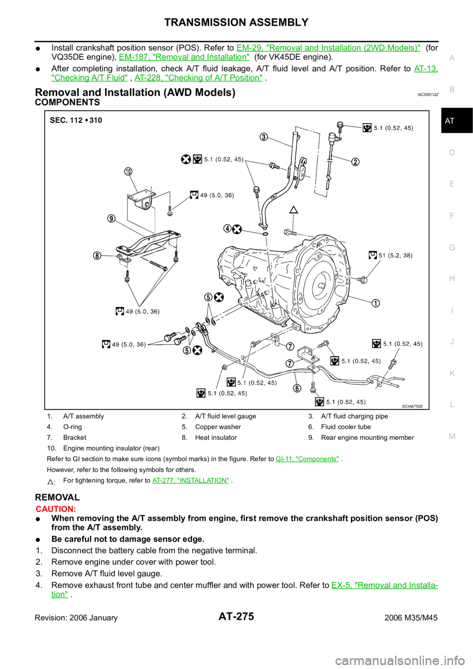
Removal and Installation (AWD Models) NCS001QZ
COMPONENTS
REMOVAL
CAUTION:
When removing the A/T assembly from engine, first remove the crankshaft position sensor (POS)
from the A/T assembly.
Be careful not to damage sensor edge.
1. Disconnect the battery cable from the negative terminal.
2. Remove engine under cover with power tool.
3. Remove A/T fluid level gauge.
4. Remove exhaust front tube and center muffler and with power tool. Refer to EX-5, "
Removal and Installa-
tion" .
1. A/T assembly 2. A/T fluid level gauge 3. A/T fluid charging pipe
4. O-ring 5. Copper washer 6. Fluid cooler tube
7. Bracket 8. Heat insulator 9. Rear engine mounting member
10. Engine mounting insulator (rear)
Refer to GI section to make sure icons (symbol marks) in the figure. Refer to GI-11, "
Components" .
However, refer to the following symbols for others.
:For tightening torque, refer to AT-277, "
INSTALLATION" .
SCIA6753E
Page 356 of 5621

TRANSMISSION ASSEMBLY
AT-277
D
E
F
G
H
I
J
K
L
MA
B
AT
Revision: 2006 January2006 M35/M45
INSPECTION
Installation and Inspection of Torque Converter
After inserting a torque converter to a A/T, be sure to check dis-
tance “A” to ensure it is within the reference value limit.
INSTALLATION
Install the removed parts in the reverse order of the removal, while paying attention to the following work.
When installing A/T assembly to the engine assembly, attach the
fixing bolts in accordance with the following standard.
Align the positions of tightening bolts for drive plate with those of
the torque converter, and temporarily tighten the bolts. Then,
tighten the bolts with the specified torque. Refer to AT- 2 7 5 ,
"COMPONENTS" .
CAUTION:
When turning crankshaft, turn it clockwise as viewed from
the front of the engine.
When tightening the tightening bolts for the torque con-
verter after fixing the crankshaft pulley bolts, be sure to
confirm the tightening torque of the crankshaft pulley
mounting bolts. Refer to EM-72, "
INSTALLATION" .
After converter is installed to drive plate, rotate crankshaft
several turns and check to be sure that A/T rotates freely without binding.
Install crankshaft position sensor (POS). Refer to EM-36, "Removal and Installation (AWD Models)" .
After completing installation, check A/T fluid leakage, A/T fluid level and A/T position. Refer to AT- 1 3 ,
"Checking A/T Fluid" , AT-228, "Checking of A/T Position" . Distance “A”: 25.0 mm (0.98 in) or more
SCIA5694E
Bolt No. 1 2 3 4
Number of bolts 1 5 2 1
Bolt length
“ ”mm (in)55 (2.17) 65 (2.56) 35 (1.38) 40 (1.57)
Tightening torque
Nꞏm (kg-m, ft-lb)75
(7.7, 55)47
(4.8, 35)34
(3.5, 25)
SCIA4600E
SCIA2288E
Page 3126 of 5621
![INFINITI M35 2006 Factory User Guide FRONT TIMING CHAIN CASE
EM-63
[VQ35DE]
C
D
E
F
G
H
I
J
K
L
MA
EM
Revision: 2006 January2006 M35/M45
10. Rotate crankshaft pulley in normal direction (clockwise when viewed from front) to c](/img/42/57023/w960_57023-3125.png "INFINITI M35 2006 Factory User Guide FRONT TIMING CHAIN CASE
EM-63
[VQ35DE]
C
D
E
F
G
H
I
J
K
L
MA
EM
Revision: 2006 January2006 M35/M45
10. Rotate crankshaft pulley in normal direction (clockwise when viewed from front) to c")
FRONT TIMING CHAIN CASE
EM-63
[VQ35DE]
C
D
E
F
G
H
I
J
K
L
MA
EM
Revision: 2006 January2006 M35/M45
10. Rotate crankshaft pulley in normal direction (clockwise when viewed from front) to confirm it turns
smoothly.
11. For the following operations, perform steps in the reverse order of removal.
INSPECTION AFTER INSTALLATION
Inspection for Leaks
The following are procedures for checking fluids leak, lubricates leak.
Before starting engine, check oil/fluid levels including engine coolant and engine oil. If less than required
quantity, fill to the specified level. Refer to MA-12, "
RECOMMENDED FLUIDS AND LUBRICANTS" .
Use procedure below to check for fuel leakage.
–Turn ignition switch “ON” (with engine stopped). With fuel pressure applied to fuel piping, check for fuel
leakage at connection points.
–Start engine. With engine speed increased, check again for fuel leakage at connection points.
Run engine to check for unusual noise and vibration.
NOTE:
If hydraulic pressure inside chain tensioner drops after removal/installation, slack in guide may generate a
pounding noise during and just after the engine start. However, this does not indicate an unusualness.
Noise will stop after hydraulic pressure rises.
Warm up engine thoroughly to make sure there is no leakage of fuel, or any oil/fluids including engine oil
and engine coolant.
Bleed air from lines and hoses of applicable lines, such as in cooling system.
After cooling down engine, again check oil/fluid levels including engine oil and engine coolant. Refill to the
specified level, if necessary.
Summary of the inspection items:
* Transmission/transaxle/CVT fluid, power steering fluid, brake fluid, etc. Item Before starting engine Engine running After engine stopped
Engine coolant Level Leakage Level
Engine oil Level Leakage Level
Other oils and fluid* Level Leakage Level
Fuel Leakage Leakage Leakage
Page 3168 of 5621
![INFINITI M35 2006 Factory User Guide CYLINDER HEAD
EM-105
[VQ35DE]
C
D
E
F
G
H
I
J
K
L
MA
EM
Revision: 2006 January2006 M35/M45
e. Turn all cylinder head bolts 90 degrees clockwise (angle tighten-
ing).
CAUTION:
Check the tightening a](/img/42/57023/w960_57023-3167.png "INFINITI M35 2006 Factory User Guide CYLINDER HEAD
EM-105
[VQ35DE]
C
D
E
F
G
H
I
J
K
L
MA
EM
Revision: 2006 January2006 M35/M45
e. Turn all cylinder head bolts 90 degrees clockwise (angle tighten-
ing).
CAUTION:
Check the tightening a")
CYLINDER HEAD
EM-105
[VQ35DE]
C
D
E
F
G
H
I
J
K
L
MA
EM
Revision: 2006 January2006 M35/M45
e. Turn all cylinder head bolts 90 degrees clockwise (angle tighten-
ing).
CAUTION:
Check the tightening angle by using the angle wrench
(SST). Avoid judgment by visual inspection without SST.
Check tightening angle indicated on the angle wrench indica-
tor plate.
f. Turn all cylinder head bolts 90 degrees clockwise again (angle
tightening).
4. After installing cylinder head, measure distance between front
end faces of cylinder block and cylinder head (left and right
banks).
If measured value is out of the standard, re-install cylinder
head.
5. Install in the reverse order of removal after this step.
INSPECTION AFTER INSTALLATION
Inspection for Leaks
The following are procedures for checking fluids leak, lubricates leak and exhaust gases leak.
Before starting engine, check oil/fluid levels including engine coolant and engine oil. If less than required
quantity, fill to the specified level. Refer to MA-12, "
RECOMMENDED FLUIDS AND LUBRICANTS" .
Use procedure below to check for fuel leakage.
–Turn ignition switch “ON” (with engine stopped). With fuel pressure applied to fuel piping, check for fuel
leakage at connection points.
–Start engine. With engine speed increased, check again for fuel leakage at connection points.
Run engine to check for unusual noise and vibration.
Warm up engine thoroughly to make sure there is no leakage of fuel, exhaust gases, or any oil/fluids
including engine oil and engine coolant.
Bleed air from lines and hoses of applicable lines, such as in cooling system.
After cooling down engine, again check oil/fluid levels including engine oil and engine coolant. Refill to the
specified level, if necessary.
Summary of the inspection items:
* Transmission/transaxle/CVT fluid, power steering fluid, brake fluid, etc.
PBIC0888E
Standard : 14.1 - 14.9 mm (0.555 - 0.587 in)
EMQ0662D
Item Before starting engine Engine running After engine stopped
Engine coolant Level Leakage Level
Engine oil Level Leakage Level
Other oils and fluid* Level Leakage Level
Fuel Leakage Leakage Leakage
Exhaust gases — Leakage —
Page 3180 of 5621
![INFINITI M35 2006 Factory User Guide ENGINE ASSEMBLY
EM-117
[VQ35DE]
C
D
E
F
G
H
I
J
K
L
MA
EM
Revision: 2006 January2006 M35/M45
INSPECTION AFTER INSTALLATION
Inspection for Leaks
The following are procedures for checking fluids leak, l](/img/42/57023/w960_57023-3179.png "INFINITI M35 2006 Factory User Guide ENGINE ASSEMBLY
EM-117
[VQ35DE]
C
D
E
F
G
H
I
J
K
L
MA
EM
Revision: 2006 January2006 M35/M45
INSPECTION AFTER INSTALLATION
Inspection for Leaks
The following are procedures for checking fluids leak, l")
ENGINE ASSEMBLY
EM-117
[VQ35DE]
C
D
E
F
G
H
I
J
K
L
MA
EM
Revision: 2006 January2006 M35/M45
INSPECTION AFTER INSTALLATION
Inspection for Leaks
The following are procedures for checking fluids leak, lubricates leak and exhaust gases leak.
Before starting engine, check oil/fluid levels including engine coolant and engine oil. If less than required
quantity, fill to the specified level. Refer to MA-12, "
RECOMMENDED FLUIDS AND LUBRICANTS" .
Use procedure below to check for fuel leakage.
–Turn ignition switch “ON” (with engine stopped). With fuel pressure applied to fuel piping, check for fuel
leakage at connection points.
–Start engine. With engine speed increased, check again for fuel leakage at connection points.
Run engine to check for unusual noise and vibration.
Warm up engine thoroughly to make sure there is no leakage of fuel, exhaust gases, or any oil/fluids
including engine oil and engine coolant.
Bleed air from lines and hoses of applicable lines, such as in cooling system.
After cooling down engine, again check oil/fluid levels including engine oil and engine coolant. Refill to the
specified level, if necessary.
Summary of the inspection items:
* Transmission/transaxle/CVT fluid, power steering fluid, brake fluid, etc. Item Before starting engine Engine running After engine stopped
Engine coolant Level Leakage Level
Engine oil Level Leakage Level
Other oils and fluid* Level Leakage Level
Fuel Leakage Leakage Leakage
Exhaust gases — Leakage —