check transmission fluid INFINITI M35 2006 Factory Owner's Manual
[x] Cancel search | Manufacturer: INFINITI, Model Year: 2006, Model line: M35, Model: INFINITI M35 2006Pages: 5621, PDF Size: 65.56 MB
Page 3185 of 5621
![INFINITI M35 2006 Factory Owners Manual EM-122
[VQ35DE]
ENGINE ASSEMBLY
Revision: 2006 January2006 M35/M45
When installing engine mounting bracket (RH and LH) on cylin-
der block, tighten two upper bolts (shown as “A” in the INFINITI M35 2006 Factory Owners Manual EM-122
[VQ35DE]
ENGINE ASSEMBLY
Revision: 2006 January2006 M35/M45
When installing engine mounting bracket (RH and LH) on cylin-
der block, tighten two upper bolts (shown as “A” in the](/img/42/57023/w960_57023-3184.png)
EM-122
[VQ35DE]
ENGINE ASSEMBLY
Revision: 2006 January2006 M35/M45
When installing engine mounting bracket (RH and LH) on cylin-
der block, tighten two upper bolts (shown as “A” in the figure)
first. Then tighten two lower bolts (shown as “B” in the figure).
Install engine mounting bracket (RH) (lower) as follows:
–Temporarily tighten mounting bolts (shown as “C”, “D” and “E” in
the figure).
–Tighten mounting bolts to the specified torque with following
mounting surfaces touched.
• Engine mounting bracket (RH) to engine mounting bracket (RH)
(lower) (shown as “C” and “D” in figure).
• Front final drive to engine mounting bracket (RH) (lower) (shown
as “E” in figure).
Make sure all engine mounting insulators are seated properly,
then tighten mounting nuts.
INSPECTION AFTER INSTALLATION
Inspection for Leaks
The following are procedures for checking fluids leak, lubricates leak and exhaust gases leak.
Before starting engine, check oil/fluid levels including engine coolant and engine oil. If less than required
quantity, fill to the specified level. Refer to MA-12, "
RECOMMENDED FLUIDS AND LUBRICANTS" .
Use procedure below to check for fuel leakage.
–Turn ignition switch “ON” (with engine stopped). With fuel pressure applied to fuel piping, check for fuel
leakage at connection points.
–Start engine. With engine speed increased, check again for fuel leakage at connection points.
Run engine to check for unusual noise and vibration.
Warm up engine thoroughly to make sure there is no leakage of fuel, exhaust gases, or any oil/fluids
including engine oil and engine coolant.
Bleed air from lines and hoses of applicable lines, such as in cooling system.
After cooling down engine, again check oil/fluid levels including engine oil and engine coolant. Refill to the
specified level, if necessary.
Summary of the inspection items:
* Transmission/transaxle/CVT fluid, power steering fluid, brake fluid, etc.
PBIC3826E
Item Before starting engine Engine running After engine stopped
Engine coolant Level Leakage Level
Engine oil Level Leakage Level
Other oils and fluid* Level Leakage Level
Fuel Leakage Leakage Leakage
Exhaust gases — Leakage —
Page 3277 of 5621
![INFINITI M35 2006 Factory Owners Manual EM-214
[VK45DE]
TIMING CHAIN
Revision: 2006 January2006 M35/M45
f. Further tighten by 90 degrees. (Angle tightening)
Check the tightening angle by referencing to the notches. The
angle between two not INFINITI M35 2006 Factory Owners Manual EM-214
[VK45DE]
TIMING CHAIN
Revision: 2006 January2006 M35/M45
f. Further tighten by 90 degrees. (Angle tightening)
Check the tightening angle by referencing to the notches. The
angle between two not](/img/42/57023/w960_57023-3276.png)
EM-214
[VK45DE]
TIMING CHAIN
Revision: 2006 January2006 M35/M45
f. Further tighten by 90 degrees. (Angle tightening)
Check the tightening angle by referencing to the notches. The
angle between two notches is 90 degrees.
15. Rotate crankshaft pulley in normal direction (clockwise when viewed from engine front) to confirm it turns
smoothly.
16. Install in the reverse order of removal after this step.
INSPECTION AFTER INSTALLATION
Inspection for Leaks
The following are procedures for checking fluids leak, lubricates leak and exhaust gases leak.
Before starting engine, check oil/fluid levels including engine coolant and engine oil. If less than required
quantity, fill to the specified level. Refer to MA-12, "
RECOMMENDED FLUIDS AND LUBRICANTS" .
Use procedure below to check for fuel leakage.
–Turn ignition switch “ON” (with engine stopped). With fuel pressure applied to fuel piping, check for fuel
leakage at connection points.
–Start engine. With engine speed increased, check again for fuel leakage at connection points.
Run engine to check for unusual noise and vibration.
NOTE:
If hydraulic pressure inside timing chain tensioner drops after removal/installation, slack in guide may gen-
erate a pounding noise during and just after engine start. However, this does not indicate an unusualness.
Noise will stop after hydraulic pressure rises.
Warm up engine thoroughly to make sure there is no leakage of fuel, exhaust gases, or any oil/fluids
including engine oil and engine coolant.
Bleed air from lines and hoses of applicable lines, such as in cooling system.
After cooling down engine, again check oil/fluid levels including engine oil and engine coolant. Refill to the
specified level, if necessary.
Summary of the inspection items:
* Transmission/transaxle/CVT fluid, power steering fluid, brake fluid, etc.
PBIC2346E
Item Before starting engine Engine running After engine stopped
Engine coolant Level Leakage Level
Engine oil Level Leakage Level
Other oils and fluid* Level Leakage Level
Fuel Leakage Leakage Leakage
Exhaust gases — Leakage —
Page 3285 of 5621
![INFINITI M35 2006 Factory Owners Manual EM-222
[VK45DE]
CAMSHAFT
Revision: 2006 January2006 M35/M45
4. Crank the engine, and then make sure that engine oil comes out
from intake valve timing control cover oil hole. End crank after INFINITI M35 2006 Factory Owners Manual EM-222
[VK45DE]
CAMSHAFT
Revision: 2006 January2006 M35/M45
4. Crank the engine, and then make sure that engine oil comes out
from intake valve timing control cover oil hole. End crank after](/img/42/57023/w960_57023-3284.png)
EM-222
[VK45DE]
CAMSHAFT
Revision: 2006 January2006 M35/M45
4. Crank the engine, and then make sure that engine oil comes out
from intake valve timing control cover oil hole. End crank after
checking.
WA R N I N G :
Be careful not to touch rotating parts (drive belt, idler pul-
ley, and crankshaft pulley, etc.).
CAUTION:
Engine oil may squirt from intake valve timing control sole-
noid valve installation hole during cranking. Use a shop
cloth to prevent the engine components and the vehicle. Do
not allow engine oil to get on rubber components such as
drive belt or engine mount insulators. Immediately wipe off
any splashed engine oil.
Clean oil groove between oil strainer and intake valve timing control solenoid valve if engine oil does not
come out from intake valve timing control cover oil hole. Refer to LU-24, "
LUBRICATION SYSTEM" .
5. Remove components between intake valve timing control solenoid valve and camshaft sprocket (INT),
and then check each oil groove for clogging.
Clean oil groove if necessary. Refer to LU-24, "LUBRICATION SYSTEM" .
6. After inspection, install removed parts.
INSPECTION AFTER INSTALLATION
Inspection for Leaks
The following are procedures for checking fluids leak, lubricates leak and exhaust gases leak.
Before starting engine, check oil/fluid levels including engine coolant and engine oil. If less than required
quantity, fill to the specified level. Refer to MA-12, "
RECOMMENDED FLUIDS AND LUBRICANTS" .
Use procedure below to check for fuel leakage.
–Turn ignition switch “ON” (with engine stopped). With fuel pressure applied to fuel piping, check for fuel
leakage at connection points.
–Start engine. With engine speed increased, check again for fuel leakage at connection points.
Run engine to check for unusual noise and vibration.
NOTE:
If hydraulic pressure inside timing chain tensioner drops after removal/installation, slack in guide may gen-
erate a pounding noise during and just after engine start. However, this does not indicate an unusualness.
Noise will stop after hydraulic pressure rises.
Warm up engine thoroughly to make sure there is no leakage of fuel, exhaust gases, or any oil/fluids
including engine oil and engine coolant.
Bleed air from lines and hoses of applicable lines, such as in cooling system.
After cooling down engine, again check oil/fluid levels including engine oil and engine coolant. Refill to the
specified level, if necessary.
Summary of the inspection items:
* Transmission/transaxle/CVT fluid, power steering fluid, brake fluid, etc.
Valve ClearanceNBS004PB
INSPECTION
In cases of removing/installing or replacing camshaft and valve-related parts, or of unusual engine conditions
due to changes in valve clearance (found malfunctions during starting, idling or causing noise), perform
inspection as follows:
1. Remove rocker covers (right and left bank). Refer to EM-199, "
ROCKER COVER" .
PBIC2848E
Item Before starting engine Engine running After engine stopped
Engine coolant Level Leakage Level
Engine oil Level Leakage Level
Other oils and fluid* Level Leakage Level
Fuel Leakage Leakage Leakage
Exhaust gases — Leakage —
Page 3310 of 5621
![INFINITI M35 2006 Factory Owners Manual ENGINE ASSEMBLY
EM-247
[VK45DE]
C
D
E
F
G
H
I
J
K
L
MA
EM
Revision: 2006 January2006 M35/M45
Separation Work
1. Install engine slingers into front of cylinder head (left bank) and
rear of cylinder h INFINITI M35 2006 Factory Owners Manual ENGINE ASSEMBLY
EM-247
[VK45DE]
C
D
E
F
G
H
I
J
K
L
MA
EM
Revision: 2006 January2006 M35/M45
Separation Work
1. Install engine slingers into front of cylinder head (left bank) and
rear of cylinder h](/img/42/57023/w960_57023-3309.png)
ENGINE ASSEMBLY
EM-247
[VK45DE]
C
D
E
F
G
H
I
J
K
L
MA
EM
Revision: 2006 January2006 M35/M45
Separation Work
1. Install engine slingers into front of cylinder head (left bank) and
rear of cylinder head (right bank).
2. Remove engine mounting insulators (RH and LH) under side nut with power tool.
3. Lift with hoist and separate engine and transmission assembly from front suspension member.
CAUTION:
Avoid damage to and oil/grease smearing or spills onto engine mounting insulator.
4. Remove alternator. Refer to SC-23, "
CHARGING SYSTEM" .
5. Remove starter motor. Refer to SC-10, "
STARTING SYSTEM" .
6. Separate engine from transmission assembly. Refer to AT-271, "
TRANSMISSION ASSEMBLY" .
7. Remove engine mounting insulators (RH and LH) and brackets (RH and LH) from engine with power tool.
8. Remove rear engine mounting member and engine mounting insulator (rear) from transmission.
INSTALLATION
Note the following, and install in the reverse order of removal.
Do not allow engine mounting insulator to be damage and careful no engine oil gets on it.
For a location with a positioning pin, insert it securely into hole of mating part.
For a part with a specified installation orientation, refer to component figure in EM-244, "Components" .
When installing engine mounting brackets (RH and LH) on cylin-
der block, tighten two upper bolts (shown as “A” in the figure)
first. Then tighten two lower bolts (shown as “B” in the figure).
NOTE:
Figure shows LH bank.
INSPECTION AFTER INSTALLATION
Inspection for Leaks
The following are procedure for checking fluids leak, lubricates leak and exhaust gases leak.
Before starting engine, check oil/fluid levels including engine coolant and engine oil. If less than required
quantity, fill to the specified level. Refer to MA-12, "
RECOMMENDED FLUIDS AND LUBRICANTS" .
Use procedure below to check for fuel leakage.
–Turn ignition switch “ON” (with engine stopped). With fuel pressure applied to fuel piping, check for fuel
leakage at connection points.
–Start engine. With engine speed increased, check again for fuel leakage at connection points.
Run engine to check for unusual noise and vibration.
Warm up engine thoroughly to make sure there is no leakage of fuel, exhaust gases, or any oil/fluids
including engine oil and engine coolant.
Bleed air from lines and hoses of applicable lines, such as in cooling system.
After cooling down engine, again check oil/fluid levels including engine oil and engine coolant. Refill to the
specified level, if necessary.Slinger bolts:
:33.4 Nꞏm (3.4 kg-m, 25 ft-lb)
PBIC2447E
PBIC3305E
Page 3468 of 5621

PRECAUTIONS
GI-5
C
D
E
F
G
H
I
J
K
L
MB
GI
Revision: 2006 January2006 M35/M45
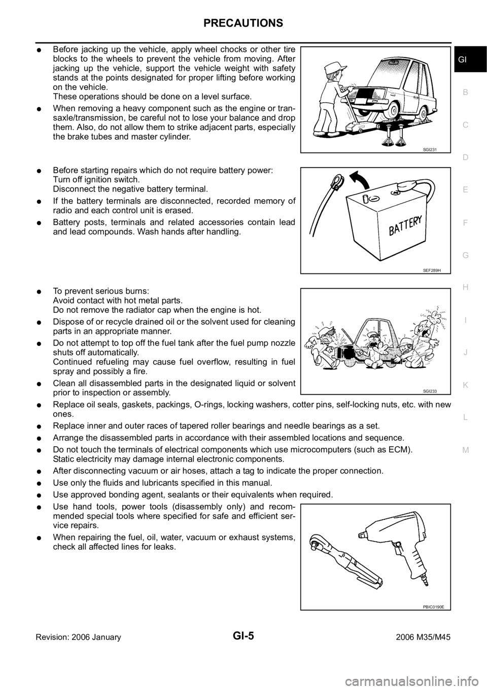
Before jacking up the vehicle, apply wheel chocks or other tire
blocks to the wheels to prevent the vehicle from moving. After
jacking up the vehicle, support the vehicle weight with safety
stands at the points designated for proper lifting before working
on the vehicle.
These operations should be done on a level surface.
When removing a heavy component such as the engine or tran-
saxle/transmission, be careful not to lose your balance and drop
them. Also, do not allow them to strike adjacent parts, especially
the brake tubes and master cylinder.
Before starting repairs which do not require battery power:
Turn off ignition switch.
Disconnect the negative battery terminal.
If the battery terminals are disconnected, recorded memory of
radio and each control unit is erased.
Battery posts, terminals and related accessories contain lead
and lead compounds. Wash hands after handling.
To prevent serious burns:
Avoid contact with hot metal parts.
Do not remove the radiator cap when the engine is hot.
Dispose of or recycle drained oil or the solvent used for cleaning
parts in an appropriate manner.
Do not attempt to top off the fuel tank after the fuel pump nozzle
shuts off automatically.
Continued refueling may cause fuel overflow, resulting in fuel
spray and possibly a fire.
Clean all disassembled parts in the designated liquid or solvent
prior to inspection or assembly.
Replace oil seals, gaskets, packings, O-rings, locking washers, cotter pins, self-locking nuts, etc. with new
ones.
Replace inner and outer races of tapered roller bearings and needle bearings as a set.
Arrange the disassembled parts in accordance with their assembled locations and sequence.
Do not touch the terminals of electrical components which use microcomputers (such as ECM).
Static electricity may damage internal electronic components.
After disconnecting vacuum or air hoses, attach a tag to indicate the proper connection.
Use only the fluids and lubricants specified in this manual.
Use approved bonding agent, sealants or their equivalents when required.
Use hand tools, power tools (disassembly only) and recom-
mended special tools where specified for safe and efficient ser-
vice repairs.
When repairing the fuel, oil, water, vacuum or exhaust systems,
check all affected lines for leaks.
SGI231
SEF289H
SGI233
PBIC0190E
Page 3643 of 5621

IDX-2
ALPHABETICAL INDEX
A
A/C air flow ...................................................... ATC-37
A/C component layout ..................................... ATC-25
A/C compressor mounting ........... ATC-155, ATC-158,
ATC-159
, ATC-160, ATC-162, ATC-164, ATC-165,
ATC-167
, ATC-168, ATC-169
A/C compressor precaution ............................. ATC-12
A/C compressor special service tool ................ ATC-16
A/C control operation (auto A/C) ...................... ATC-33
A/C diagnostic work flow (auto A/C) .............. ATC-111
A/C evaporator ............................................... ATC-168
A/C HFC134a (R134a) system precaution ........ ATC-6
A/C HFC134a (R134a) system service procedure .......
ATC-151
A/C HFC134a (R134a) system service tools ... ATC-17
A/C HFC134a system service equipment precaution ...
ATC-13
A/C lubricant (R134a) ...................................... ATC-26
A/C lubrication oil ........................................... ATC-174
A/C operational check ...................................... ATC-64
A/C self-diagnoses (auto A/C) ........ ATC-55, ATC-111
A/C service data specification ........................ ATC-174
A/C system description (auto A/C) ................... ATC-29
A/C trouble diagnoses (auto A/C) .................... ATC-40
A/C, A - Wiring diagram ................................... ATC-46
A/T fluid checking ...................... AT-13, AT-53, MA-29
A/T fluid cooler cleaning .................................... AT-14
A/T fluid replacement ............................. AT-12, MA-31
A/T fluid temperature sensor ........................... AT-135
A/T IND - Wiring diagram .................................... DI-57
A/T self-diagnoses ............................... AT-92, AT-103
A/T shift lock system ........................................ AT-229
A/T shift lock system - Wiring diagram ............ AT-230
A/T trouble diagnoses ........................................ AT-44
Accelerator control system ............................... ACC-3
Accelerator pedal position (APP) sensor ........ EC-626,
EC-633
, EC-647, EC-1358, EC-1365, EC-1379
Accelerator pedal released position learning .... EC-95,
EC-806
AF1B1-Wiring diagram ...... EC-249, EC-258, EC-267,
EC-277
, EC-657, EC-972, EC-981, EC-990, EC-1000,
EC-1389
AF1B2-Wiring diagram ...... EC-251, EC-260, EC-269,
EC-279
, EC-659, EC-974, EC-983, EC-992, EC-1002,
EC-1391
AF1HB1-Wiring diagram .................... EC-183, EC-905
AF1HB2-Wiring diagram .................... EC-185, EC-907
Air bag .............................................................. SRS-3
Air bag precautions ........................................... SRS-3
Air cleaner and air duct(VK45DE) ................... EM-177
Air cleaner and air duct(VQ35DE) .................... EM-17
Air cleaner filter replacement ............................ MA-25
Air cleaner filter replacement(VQ35DE) ........... MA-18
Air cleaner filter(VQ35DE) ................................ EM-18
Air conditioner cut control .................... EC-35, EC-745
Air flow meter - See Mass air flow sensor ...... EC-205,
EC-214
, EC-927, EC-936
Air fuel ratio sensor 1 ......... EC-246, EC-256, EC-265, EC-274
, EC-655, EC-969, EC-979, EC-988, EC-997,
EC-1387
Air fuel ratio sensor 1 heater ............. EC-182, EC-904
Air mix. door motor ......................... ATC-83, ATC-141
Alternator ........................................................... SC-23
Ambient sensor ............................. ATC-113, ATC-126
Angular tightening application ............................. EM-6
Angular tightening application(VK45DE) ........ EM-164
APPS1 - Wiring diagram ................. EC-628, EC-1360
APPS2 - Wiring diagram ................. EC-635, EC-1367
APPS3 - Wiring diagram ................. EC-649, EC-1381
ASC/BS - Wiring diagram ............... EC-587, EC-1313
ASC/SW - Wiring diagram .............. EC-570, EC-1296
ASCBOF - Wiring diagram .............. EC-708, EC-1450
ASCD .................................................. EC-36, EC-746
ASCD (automatic speed control device) ........... ACS-3
ASCIND - Wiring diagram ............... EC-715, EC-1457
AT indicator lamp ................................................ DI-56
Auto air conditioner - Wiring diagram ............. ATC-46
Auto amp ...................................................... ATC-125
Auto anti-dazzling inside mirror .......... GW-71, GW-72
Automatic amplifier ........... ATC-53, ATC-66, ATC-125
Automatic transmission fluid replacement ........ MA-32
AWD - Wiring diagram ....................................... TF-17
Axle ................................................................... MA-37
B
Back-up lamp ................................................... LT-246
Basic inspection .................................. EC-77, EC-788
Battery ................................................................. SC-4
Battery current sensor ....... EC-537, EC-543, EC-549,
EC-555
, EC-1263, EC-1269, EC-1275, EC-1281
Battery/Starting/Charging System Tester .......... SC-28
Battery/Starting/Charging System Tester(Battery) SC-7
Battery/Starting/Charging System Tester(Starting
system) .............................................................. SC-13
BCM (Body control module) .............................. BCS-3
Block heater(VK45DE) .................................... EM-249
Block heater(VQ35DE) ................................... EM-123
Blower motor ................................... ATC-89, ATC-132
Blower unit .................................................... ATC-130
Brake fluid level ................................................ MA-35
Brake hydraulic line ........................................... BR-12
Brake inspection ............................................... MA-36
Brake lines and cables inspection .................... MA-35
Brake pedal .......................................................... BR-6
Brake switch ................................... EC-598, EC-1329
BRK/SW - Wiring diagram .............. EC-600, EC-1331
Bulb specifications ........................................... LT-315
Bumper, front ...................................................... EI-11
Bumper, rear ....................................................... EI-14
C
Camshaft inspection(VK45DE) ....................... EM-216
Camshaft inspection(VQ35DE) ......................... EM-86
Camshaft position sensor (PHASE) EC-383, EC-1106
Camshaft(VK45DE) ........................................ EM-215
Page 4808 of 5621

CHASSIS AND BODY MAINTENANCE
MA-31
C
D
E
F
G
H
I
J
K
MA
B
MA
Revision: 2006 January2006 M35/M45
Changing A/T FluidNLS00081
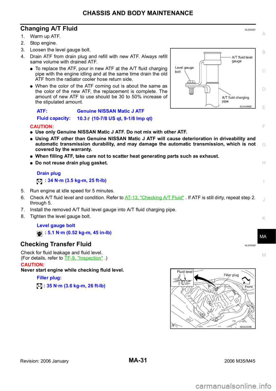
1. Warm up ATF.
2. Stop engine.
3. Loosen the level gauge bolt.
4. Drain ATF from drain plug and refill with new ATF. Always refill
same volume with drained ATF.
To replace the ATF, pour in new ATF at the A/T fluid charging
pipe with the engine idling and at the same time drain the old
ATF from the radiator cooler hose return side.
When the color of the ATF coming out is about the same as
the color of the new ATF, the replacement is complete. The
amount of new ATF to use should be 30 to 50% increase of
the stipulated amount.
CAUTION:
Use only Genuine NISSAN Matic J ATF. Do not mix with other ATF.
Using ATF other than Genuine NISSAN Matic J ATF will cause deterioration in driveability and
automatic transmission durability, and may damage the automatic transmission, which is not
covered by the warranty.
When filling ATF, take care not to scatter heat generating parts such as exhaust.
Do not reuse drain plug gasket.
5. Run engine at idle speed for 5 minutes.
6. Check A/T fluid level and condition. Refer to AT- 1 3 , "
Checking A/T Fluid" . If ATF is still dirty, repeat step 2.
through 5.
7. Install the removed A/T fluid level gauge into A/T fluid charging pipe.
8. Tighten the level gauge bolt.
Checking Transfer FluidNLS00082
Check for fluid leakage and fluid level.
(For details, refer to TF-9, "
Inspection" .)
CAUTION:
Never start engine while checking fluid level.ATF: Genuine NISSAN Matic J ATF
Fluid capacity:
10.3 (10-7/8 US qt, 9-1/8 lmp qt)
Drain plug
: 34 Nꞏm (3.5 kg-m, 25 ft-lb)
Level gauge bolt
: 5.1 Nꞏm (0.52 kg-m, 45 in-lb)
SCIA4896E
Filler plug:
: 35 Nꞏm (3.6 kg-m, 26 ft-lb)
SDIA2028E
Page 5509 of 5621

TF-44
TRANSFER ASSEMBLY
Revision: 2006 January2006 M35/M45
TRANSFER ASSEMBLYPFP:33100
Removal and InstallationNDS000E4
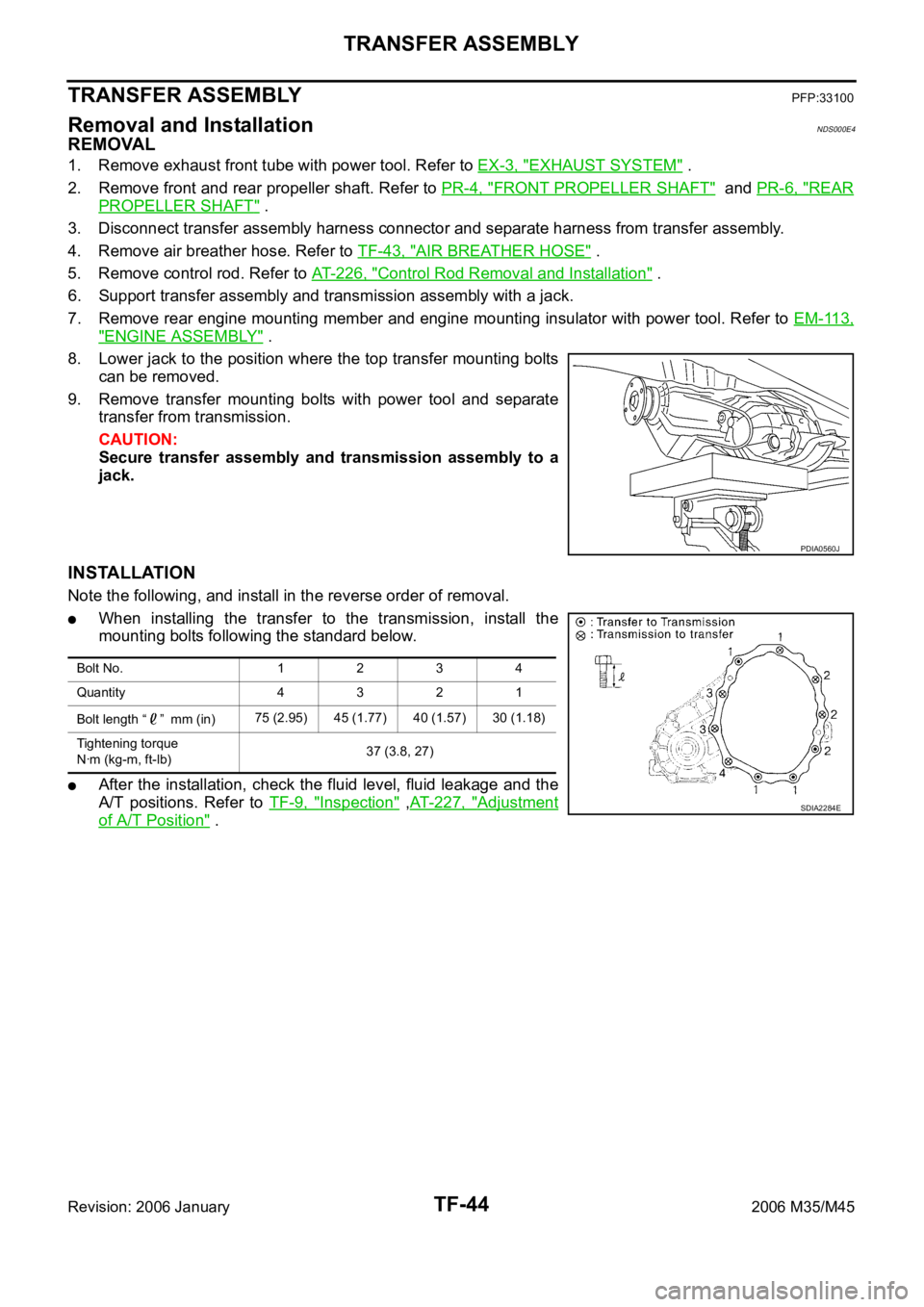
REMOVAL
1. Remove exhaust front tube with power tool. Refer to EX-3, "EXHAUST SYSTEM" .
2. Remove front and rear propeller shaft. Refer to PR-4, "
FRONT PROPELLER SHAFT" and PR-6, "REAR
PROPELLER SHAFT" .
3. Disconnect transfer assembly harness connector and separate harness from transfer assembly.
4. Remove air breather hose. Refer to TF-43, "
AIR BREATHER HOSE" .
5. Remove control rod. Refer to AT-226, "
Control Rod Removal and Installation" .
6. Support transfer assembly and transmission assembly with a jack.
7. Remove rear engine mounting member and engine mounting insulator with power tool. Refer to EM-113,
"ENGINE ASSEMBLY" .
8. Lower jack to the position where the top transfer mounting bolts
can be removed.
9. Remove transfer mounting bolts with power tool and separate
transfer from transmission.
CAUTION:
Secure transfer assembly and transmission assembly to a
jack.
INSTALLATION
Note the following, and install in the reverse order of removal.
When installing the transfer to the transmission, install the
mounting bolts following the standard below.
After the installation, check the fluid level, fluid leakage and the
A/T positions. Refer to TF-9, "
Inspection" ,AT- 2 2 7 , "Adjustment
of A/T Position" .
PDIA0560J
Bolt No. 1234
Quantity 4321
Bolt length “ ” mm (in)75 (2.95) 45 (1.77) 40 (1.57) 30 (1.18)
Tightening torque
Nꞏm (kg-m, ft-lb)37 (3.8, 27)
SDIA2284E