Body INFINITI M35 2006 Factory Service Manual
[x] Cancel search | Manufacturer: INFINITI, Model Year: 2006, Model line: M35, Model: INFINITI M35 2006Pages: 5621, PDF Size: 65.56 MB
Page 3044 of 5621

BODY SIDE TRIM
EI-39
C
D
E
F
G
H
J
K
L
MA
B
EI
Revision: 2006 January2006 M35/M45
FRONT BODY SIDE WELT
Removal
1. Remove center pillar lower garnish.
2. Remove center kicking plate inner.
3. Remove front body side welt.
Installation
Install in the reverse order of removal.
CENTER PILLAR LOWER GARNISH
Removal
Remove center pillar lower garnish mounting clips using a screw-
driver, and then remove center pillar lower garnish.
CAUTION:
Be careful not to damage the body.
Installation
Install in the reverse order of removal.
CENTER PILLAR UPPER GARNISH
Removal
1. Remove center pillar lower garnish.
2. Remove front seat belt floor anchor bolt and front seat belt shoulder anchor bolt. Refer to SB-30,
"Removal and Installation of Front Seat Belt" .
3. Remove front body side welt and rear body side welt.
4. Remove center pillar upper garnish mounting clips using a
screwdriver, and then remove center pillar upper garnish.
Installation
Install in the reverse order of removal.
PIIB2763J
PIIB2764J
Page 3045 of 5621

EI-40
BODY SIDE TRIM
Revision: 2006 January2006 M35/M45
REAR KICKING PLATE OUTER
Removal
Remove rear kicking plate outer mounting clips using a clip clamp
remover, and then remove kicking plate outer.
Installation
Install in the reverse order of removal.
REAR KICKING PLATE INNER
Removal
1. Remove rear seat cushion. Refer to SE-176, "Removal and Installation" .
2. Remove kicking plate inner mounting clips using a clip clamp
remover, and then remove kicking plate inner.
Installation
Install in the reverse order of removal.
REAR BODY SIDE WELT
Removal
1. Remove center pillar lower garnish.
2. Remove rear seat cushion. Refer to SE-176, "
Removal and Installation" .
3. Remove rear kicking plate inner.
4. Remove rear body side welt.
Installation
Install in the reverse order of removal.
PIIB2765J
PIIB2766J
Page 3046 of 5621

BODY SIDE TRIM
EI-41
C
D
E
F
G
H
J
K
L
MA
B
EI
Revision: 2006 January2006 M35/M45
REAR WHEEL HOUSE GARNISH
Removal
1. Remove rear seat cushion and rear seatback. Refer to SE-176, "Removal and Installation" .
2. Remove rear body side welt.
3. Remove clip of rear wheel house garnish.
4. Remove rear wheel house garnish.
Installation
Install in the reverse order of removal.
NOTE:
To install, check if all clips are matched over holes of panel on vehicle, then push on.
REAR PILLAR FINISHER
Removal
1. Remove rear seat cushion and rear seatback. Refer to SE-176, "Removal and Installation" .
2. Remove rear seat belt floor anchor bolt. Refer to SB-32, "
Removal and Installation of Rear Seat Belt" .
3. Remove rear kicking plate inner.
4. Remove rear wheel house garnish.
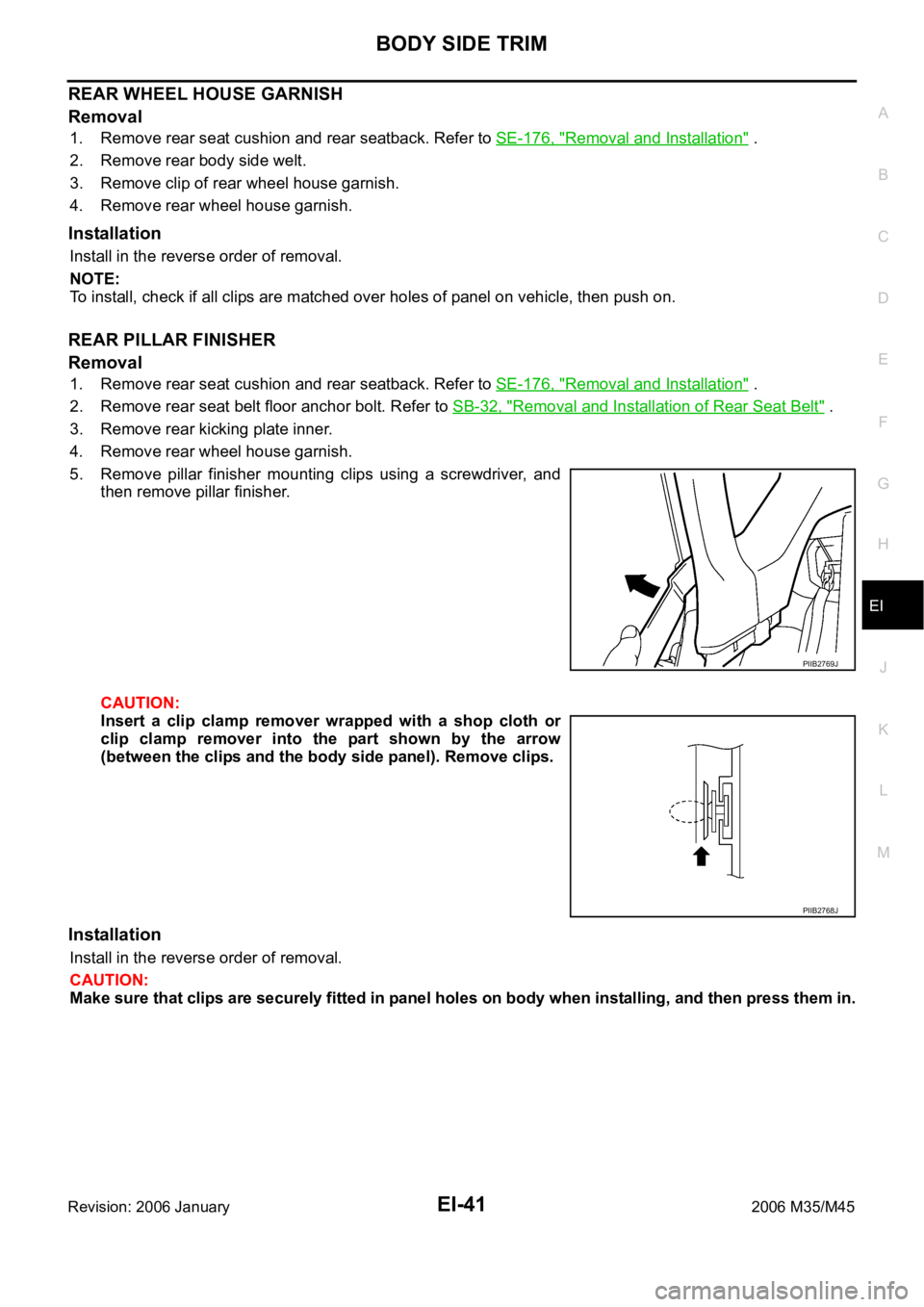
5. Remove pillar finisher mounting clips using a screwdriver, and
then remove pillar finisher.
CAUTION:
Insert a clip clamp remover wrapped with a shop cloth or
clip clamp remover into the part shown by the arrow
(between the clips and the body side panel). Remove clips.
Installation
Install in the reverse order of removal.
CAUTION:
Make sure that clips are securely fitted in panel holes on body when installing, and then press them in.
PIIB2769J
PIIB2768J
Page 3047 of 5621

EI-42
REAR PARCEL SHELF FINISHER
Revision: 2006 January2006 M35/M45
REAR PARCEL SHELF FINISHERPFP:79910
Removal and InstallationNIS0024W
REMOVAL
1. Remove rear seatback and rear seat cushion. Refer to SE-176, "Removal and Installation" .
2. Remove rear seat belt floor anchor bolt and rear seat belt shoulder anchor bolt. Refer to SB-32, "
Removal
and Installation of Rear Seat Belt" .
3. Disengage child anchor cover front pawls, and then pull out child anchor cover (LH/RH center) toward
front of vehicle. (Models with rear window sunshade)
4. Remove rear kicking plate inner, rear wheelhouse garnish, rear pillar finisher. Refer to EI-37, "
BODY SIDE
TRIM" .
1. Rear parcel shelf lid 2. High-mounted stop lamp 3. Child anchor cover
4. Rear parcel shelf finisher 5. Rear seat belt shoulder anchor cover 6. Rear window sunshade
PIIB4590E
Page 3048 of 5621

REAR PARCEL SHELF FINISHER
EI-43
C
D
E
F
G
H
J
K
L
MA
B
EI
Revision: 2006 January2006 M35/M45
5. Disconnect high-mounted stop lamp harness connector from
front side of rear parcel shelf finisher. (Models with rear window
sunshade)
6. Remove rear parcel shelf finisher mounting clip using a clip clamp remover.
7. Remove the following parts after removing rear parcel shelf finisher.
Rear speaker grille (for woofer)
High-mounted stop lamp
High-mounted stop lamp harness
INSTALLATION
Install in the reverse order of removal.
CAUTION:
Make sure that clips are securely fitted in panel holes on body when installing, and then press them in.
Rear Window SunshadeNIS0024X
REMOVAL AND INSTALLATION
CAUTION:
Be careful not to damage the rear window glass.
Removal
1. Remove rear parcel shelf finisher. Refer to EI-42, "REAR PARCEL SHELF FINISHER" .
2. Disconnect rear window sunshade harness connector.
3. Remove rear window sunshade mounting bolts.
4. Lift up rear window sunshade and pull out locating pin from body side panel hole, and then remove rear
window sunshade.
Installation
Install in the reverse order of removal.
PIIB5130E
Page 3055 of 5621

EI-50
FLOOR TRIM
Revision: 2006 January2006 M35/M45
FLOOR TRIMPFP:74902
Removal and InstallationNIS00252
REMOVAL
1. Remove front seat (LH/RH) and rear seat cushion. Refer to SE-167, "Removal and Installation" and SE-
176, "Removal and Installation" .
2. Remove accelerator pedal pad. Refer to ACC-3, "
ACCELERATOR CONTROL SYSTEM" .
3. Remove rear floor grille and foot grille. Refer to ATC-144, "
DUCTS AND GRILLES" .
4. Remove front seat belt floor anchor bolt (LH/RH). Refer to SB-30, "
Removal and Installation of Front Seat
Belt" .
5. Remove center console. Refer to IP-10, "
INSTRUMENT PANEL ASSEMBLY" .
6. Remove instrument driver lower panel and instrument passenger lower cover. Refer to IP-10, "
INSTRU-
MENT PANEL ASSEMBLY" .
7. Remove floor hook.
8. Remove dash side finisher, front kicking plate inner, center pillar lower garnish, and rear kicking plate
inner, front body side welt (LH/RH), rear body side welt (LH/RH), rear wheel house garnish. Refer to EI-
37, "BODY SIDE TRIM" .
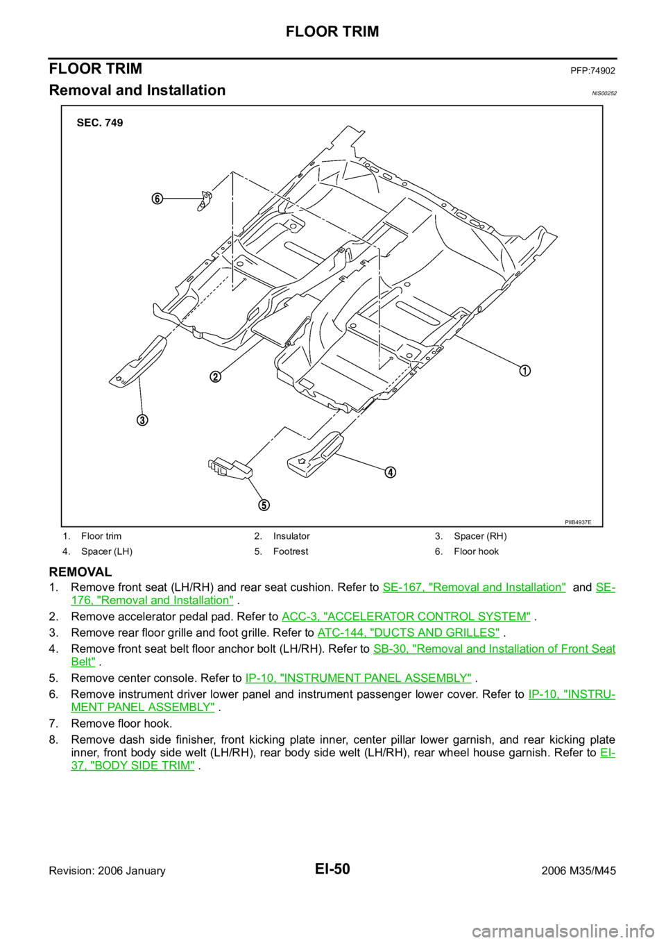
1. Floor trim 2. Insulator 3. Spacer (RH)
4. Spacer (LH) 5. Footrest 6. Floor hook
PIIB4937E
Page 3058 of 5621

HEADLINING
EI-53
C
D
E
F
G
H
J
K
L
MA
B
EI
Revision: 2006 January2006 M35/M45
REMOVAL
1. Remove front pillar garnish (LH/RH). Refer to EI-37, "BODY SIDE TRIM" .
2. Remove roof harness and antenna feeder securing clip using a clip clamp remover after removing front
pillar garnish (LH/RH), and then disconnect roof harness and antenna feeder connectors.
3. Remove rear seat cushion and seatback. Refer to SE-172, "
REAR SEAT" .
4. Remove front kicking plate inner, center pillar lower garnish, center pillar upper garnish, front body side
welt, rear kicking plate inner, rear wheelhouse garnish, rear pillar finisher, rear body side welt. Refer to EI-
37, "BODY SIDE TRIM" .
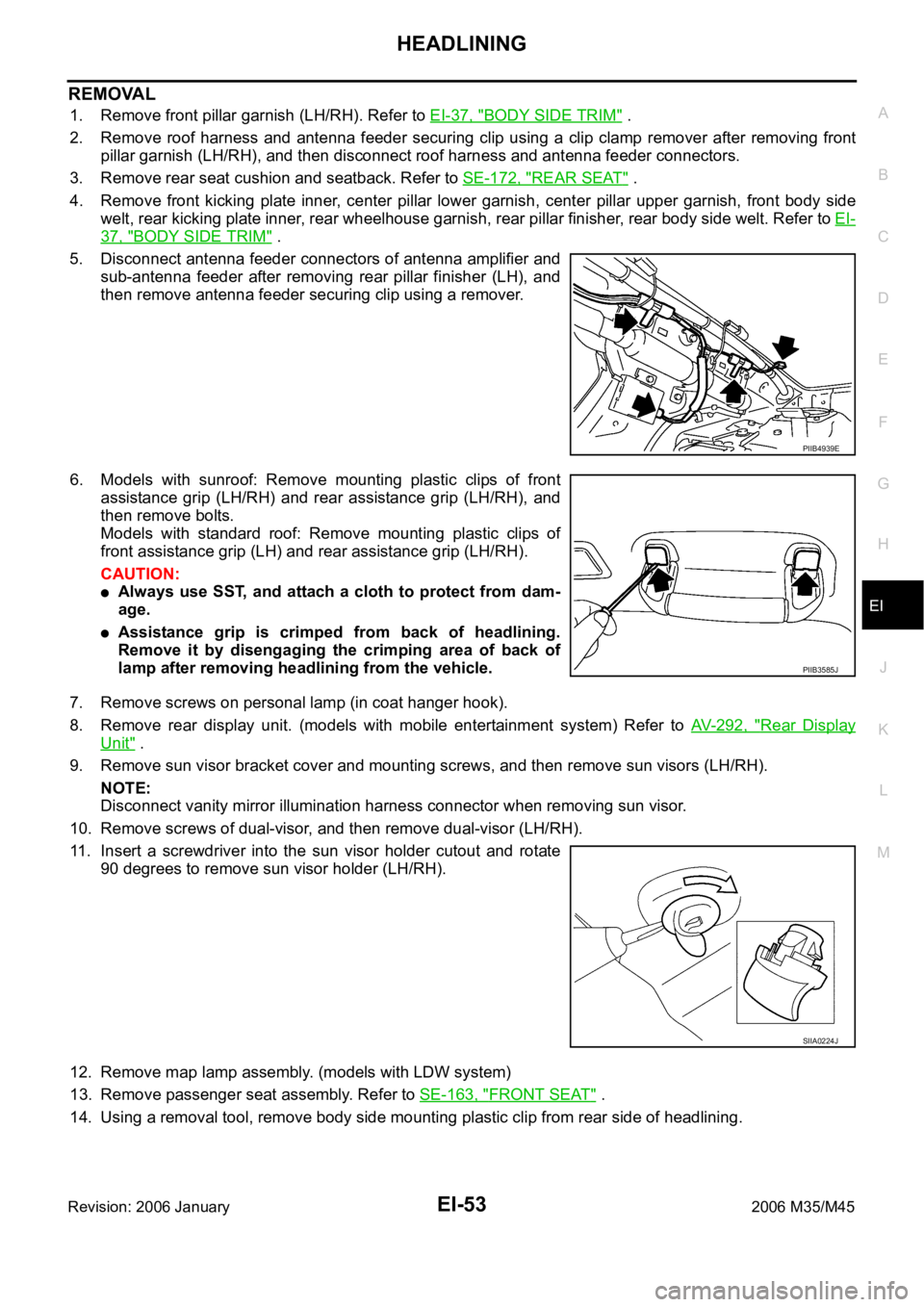
5. Disconnect antenna feeder connectors of antenna amplifier and
sub-antenna feeder after removing rear pillar finisher (LH), and
then remove antenna feeder securing clip using a remover.
6. Models with sunroof: Remove mounting plastic clips of front
assistance grip (LH/RH) and rear assistance grip (LH/RH), and
then remove bolts.
Models with standard roof: Remove mounting plastic clips of
front assistance grip (LH) and rear assistance grip (LH/RH).
CAUTION:
Always use SST, and attach a cloth to protect from dam-
age.
Assistance grip is crimped from back of headlining.
Remove it by disengaging the crimping area of back of
lamp after removing headlining from the vehicle.
7. Remove screws on personal lamp (in coat hanger hook).
8. Remove rear display unit. (models with mobile entertainment system) Refer to AV- 2 9 2 , "
Rear Display
Unit" .
9. Remove sun visor bracket cover and mounting screws, and then remove sun visors (LH/RH).
NOTE:
Disconnect vanity mirror illumination harness connector when removing sun visor.
10. Remove screws of dual-visor, and then remove dual-visor (LH/RH).
11. Insert a screwdriver into the sun visor holder cutout and rotate
90 degrees to remove sun visor holder (LH/RH).
12. Remove map lamp assembly. (models with LDW system)
13. Remove passenger seat assembly. Refer to SE-163, "
FRONT SEAT" .
14. Using a removal tool, remove body side mounting plastic clip from rear side of headlining.
PIIB4939E
PIIB3585J
SIIA0224J
Page 3131 of 5621
![INFINITI M35 2006 Factory Service Manual EM-68
[VQ35DE]
TIMING CHAIN
Revision: 2006 January2006 M35/M45
b. Insert a suitable tool into the notch at the top of front timing chain
case as shown (1).
c. Pry off case by moving the tool as shown INFINITI M35 2006 Factory Service Manual EM-68
[VQ35DE]
TIMING CHAIN
Revision: 2006 January2006 M35/M45
b. Insert a suitable tool into the notch at the top of front timing chain
case as shown (1).
c. Pry off case by moving the tool as shown](/img/42/57023/w960_57023-3130.png)
EM-68
[VQ35DE]
TIMING CHAIN
Revision: 2006 January2006 M35/M45
b. Insert a suitable tool into the notch at the top of front timing chain
case as shown (1).
c. Pry off case by moving the tool as shown (2).
U s e t h e s e a l c u t t e r [ S S T: K V 1 0 1111 0 0 ( J 3 7 2 2 8 ) ] t o c u t l i q u i d
gasket for removal.
CAUTION:
Do not use a screwdriver or something similar.
After removal, handle front timing chain case carefully so
it does not tilt, cant, or warp under a load.
27. Remove O-rings from rear timing chain case.
28. Remove water pump cover and chain tensioner cover from front timing chain case, if necessary.
U s e t h e s e a l c u t t e r [ S S T: K V 1 0 1111 0 0 ( J 3 7 2 2 8 ) ] t o c u t l i q u i d g asket for removal.
29. Remove front oil seal from front timing chain case using a suit-
able tool.
Use a screwdriver for removal.
CAUTION:
Be careful not to damage front timing chain case.
30. Remove timing chain tensioner (primary) as follows:
a. Remove lower mounting bolt.
b. Loosen upper mounting bolt slowly, and then turn timing chain
tensioner (primary) on the mounting bolt so that plunger is fully
expanded.
NOTE:
Even if plunger is fully expanded, it is not dropped from the body
of timing chain tensioner (primary).
c. Remove upper mounting bolt, and then remove timing chain ten-
sioner (primary).
SEM156F
PBIC2548E
EMQ0032D
PBIC3562E
Page 3141 of 5621
![INFINITI M35 2006 Factory Service Manual EM-78
[VQ35DE]
TIMING CHAIN
Revision: 2006 January2006 M35/M45
8. Install internal chain guide, slack guide and timing chain ten-
sioner (primary).
CAUTION:
Do not overtighten slack guide mo INFINITI M35 2006 Factory Service Manual EM-78
[VQ35DE]
TIMING CHAIN
Revision: 2006 January2006 M35/M45
8. Install internal chain guide, slack guide and timing chain ten-
sioner (primary).
CAUTION:
Do not overtighten slack guide mo](/img/42/57023/w960_57023-3140.png)
EM-78
[VQ35DE]
TIMING CHAIN
Revision: 2006 January2006 M35/M45
8. Install internal chain guide, slack guide and timing chain ten-
sioner (primary).
CAUTION:
Do not overtighten slack guide mounting bolts. It is normal
for a gap to exist under the bolt seats when mounting bolts
are tightened to the specification.
9. Install the timing chain tensioner (primary) with the following procedure:
a. Pull plunger stopper tab up (or turn lever downward) so as to
remove plunger stopper tab from the ratchet of plunger.
NOTE:
Plunger stopper tab and lever are synchronized.
b. Push plunger into the inside of tensioner body.
c. Hold plunger in the fully compressed position by engaging
plunger stopper tab with the tip of ratchet.
d. To secure lever, insert stopper pin through hole of lever into ten-
sioner body hole.
The lever parts and the tab are synchronized. Therefore, the
plunger will be secured under this condition.
NOTE:
Figure shows the example of 1.2 mm (0.047 in) diameter thin screwdriver being used as the stopper pin.
PBIC2109E
PBIC2633E
PBIC3568E
Page 3177 of 5621
![INFINITI M35 2006 Factory Service Manual EM-114
[VQ35DE]
ENGINE ASSEMBLY
Revision: 2006 January2006 M35/M45
REMOVAL
Outline
At first, remove the engine and the transmission assembly with front suspension member from vehicle down-
ward. Then INFINITI M35 2006 Factory Service Manual EM-114
[VQ35DE]
ENGINE ASSEMBLY
Revision: 2006 January2006 M35/M45
REMOVAL
Outline
At first, remove the engine and the transmission assembly with front suspension member from vehicle down-
ward. Then](/img/42/57023/w960_57023-3176.png)
EM-114
[VQ35DE]
ENGINE ASSEMBLY
Revision: 2006 January2006 M35/M45
REMOVAL
Outline
At first, remove the engine and the transmission assembly with front suspension member from vehicle down-
ward. Then separate the engine from transmission.
Preparation
1. Release fuel pressure. Refer to EC-98, "FUEL PRESSURE RELEASE" .
2. Drain engine coolant from radiator. Refer to CO-11, "
Changing Engine Coolant" .
CAUTION:
Perform this step when engine is cold.
Do not spill engine coolant on drive belts.
3. Disconnect both battery cables. Refer to SC-4, "
BATTERY" .
4. Remove the following parts:
Engine room cover (RH and LH); Refer toEM-14, "ENGINE ROOM COVER" .
Engine cover; Refer to EM-19, "INTAKE MANIFOLD COLLECTOR" .
Front road wheel and tires (power tool)
Front and rear engine undercover (power tool)
Cowl top cover (RH); Refer to EI-18, "COWL TOP" .
Air duct and air cleaner case assembly; EM-17, "AIR CLEANER AND AIR DUCT" .
5. Discharge refrigerant from A/C circuit. Refer to ATC-151, "
REFRIGERANT LINES" .
6. Remove radiator hoses (upper and lower). Refer to CO-14, "
RADIATOR" .
Engine Room LH
1. Disconnect heater hose from vehicle-side, and fit a plug onto hose end to prevent engine coolant leak.
2. Disconnect wire bonding (between vehicle to left bank cylinder head).
3. Disconnect A/C piping from A/C compressor, and temporarily fasten it on vehicle with a rope. Refer to
AT C - 1 5 1 , "
REFRIGERANT LINES" .
4. Disconnect brake booster vacuum hose.
Engine Room RH
1. Disconnect battery positive cable at vehicle side and temporarily fasten it on engine.
2. Disconnect grounding cable.
3. Disconnect fuel feed hose (with damper) and EVAP hose. Refer to EM-45, "
FUEL INJECTOR AND FUEL
TUBE" .
CAUTION:
Fit plugs onto disconnected hoses to prevent fuel leak.
4. Remove reservoir tank of power steering oil pump and piping from vehicle, and temporarily secure them
on engine. Refer to PS-29, "
POWER STEERING OIL PUMP" .
CAUTION:
When temporarily securing, keep the reservoir tank upright to avoid a fluid leak.
Vehicle inside
Follow procedure below to disconnect engine room harness connectors at passenger room side, and tempo-
rarily secure them on engine.
1. Remove passenger-side kicking plate, dash side finisher, and glove box. Refer to EI-37, "
BODY SIDE
TRIM" and IP-10, "INSTRUMENT PANEL ASSEMBLY" .
2. Disconnect engine room harness connectors at unit sides TCM, ECM and other.
3. Disengage intermediate fixing point. Pull out engine room harnesses to engine room side, and temporarily
secure them on engine.
CAUTION:
When pulling out harnesses, take care not to damage harnesses and connectors.
After temporarily securing, cover connectors with vinyl or similar material to protect against for-
eign material adhesion.