sensor INFINITI M35 2006 Factory Service Manual
[x] Cancel search | Manufacturer: INFINITI, Model Year: 2006, Model line: M35, Model: INFINITI M35 2006Pages: 5621, PDF Size: 65.56 MB
Page 567 of 5621

ATC-120
TROUBLE DIAGNOSIS
Revision: 2006 January2006 M35/M45
2. CHECK CIRCUIT CONTINUITY BETWEEN SUNLOAD SENSOR AND UNIFIED METER AND A/C AMP.
1. Turn ignition switch OFF.
2. Disconnect unified meter and A/C amp. connector.
3. Check continuity between sunload sensor harness connector
M87 terminal 2 and unified meter and A/C amp. harness con-
nector M65 terminal 62.
OK or NG
OK >> GO TO 3.
NG >> Repair harness or connector.
3. CHECK SUNLOAD SENSOR
1. Reconnect sunload sensor connector and unified meter and A/C amp. connector.
2. Refer to ATC-121, "
Sunload Sensor" .
OK or NG
OK >> 1. Replace unified meter and A/C amp.
2. Go to self-diagnosis AT C - 5 6 , "
FUNCTION CONFIRMATION PROCEDURE" and perform self-
diagnosis STEP-2. Confirm that code No. 20 is displayed.
NG >> 1. Replace sunload sensor.
2. Go to self-diagnosis AT C - 5 6 , "
FUNCTION CONFIRMATION PROCEDURE" and perform self-
diagnosis STEP-2. Confirm that code No. 20 is displayed.
4. CHECK CIRCUIT CONTINUITY BETWEEN SUNLOAD SENSOR AND UNIFIED METER AND A/C AMP.
1. Turn ignition switch OFF.
2. Disconnect unified meter and A/C amp. connector.
3. Check continuity between sunload sensor harness connector
M87 terminal 1 and unified meter and A/C amp. harness con-
nector M65 terminal 46.
4. Check continuity between sunload sensor harness connector
M87 terminal 1 and ground.
OK or NG
OK >> 1. Replace unified meter and A/C amp.
2. Go to self-diagnosis AT C - 5 6 , "
FUNCTION CONFIRMATION PROCEDURE" and perform self-
diagnosis STEP-2. Confirm that code No. 20 is displayed.
NG >> Repair harness or connector.2 – 62 : Continuity should exist.
RJIA4100E
1 – 46 : Continuity should exist.
1 – Ground : Continuity should not exist.
RJIA4101E
Page 568 of 5621

TROUBLE DIAGNOSIS
ATC-121
C
D
E
F
G
H
I
K
L
MA
B
AT C
Revision: 2006 January2006 M35/M45
COMPONENT INSPECTION
Sunload Sensor
Measure voltage between unified meter and A/C amp. harness con-
nector M65 terminal 46 and ground.
When checking sunload sensor, select a place where sun shines directly on it.
If NG, replace sunload sensor.
RJIA4102E
SHA930E
Page 569 of 5621

ATC-122
TROUBLE DIAGNOSIS
Revision: 2006 January2006 M35/M45
Intake Sensor CircuitNJS000H3
COMPONENT DESCRIPTION
Intake Sensor
The intake sensor is located on the heater & cooling unit assembly. It
converts temperature of air after it passes through the evaporator
into a resistance value which is then input to the unified meter and A/
C amp.
DIAGNOSIS PROCEDURE FOR INTAKE SENSOR
SYMPTOM: Intake sensor circuit is open or shorted. (24 or 24 is
indicated on unified meter and A/C amp. as a result of performing
self-diagnosis STEP-2.)
1. CHECK VOLTAGE BETWEEN INTAKE SENSOR AND GROUND
1. Disconnect intake sensor connector.
2. Turn ignition switch ON.
3. Check voltage between intake sensor harness connector M82
terminal 1 and ground.
OK or NG
OK >> GO TO 2.
NG >> GO TO 4.
2. CHECK CIRCUIT CONTINUITY BETWEEN INTAKE SENSOR AND UNIFIED METER AND A/C AMP.
1. Turn ignition switch OFF.
2. Disconnect unified meter and A/C amp. connector.
3. Check continuity between intake sensor harness connector M82
terminal 2 and unified meter and A/C amp. harness connector
M65 terminal 59.
OK or NG
OK >> GO TO 3.
NG >> Repair harness or connector.
RJIA4103E
RJIA4104E
1 – Ground : Approx. 5 V
RJIA4215E
2 – 59 : Continuity should exist.
RJIA4106E
Page 570 of 5621

TROUBLE DIAGNOSIS
ATC-123
C
D
E
F
G
H
I
K
L
MA
B
AT C
Revision: 2006 January2006 M35/M45
3. CHECK INTAKE SENSOR
Refer to ATC-123, "
Intake Sensor" .
OK or NG
OK >> 1. Replace unified meter and A/C amp.
2. Go to self-diagnosis AT C - 5 6 , "
FUNCTION CONFIRMATION PROCEDURE" and perform self-
diagnosis STEP-2. Confirm that code No. 20 is displayed.
NG >> 1. Replace intake sensor.
2. Go to self-diagnosis AT C - 5 6 , "
FUNCTION CONFIRMATION PROCEDURE" and perform self-
diagnosis STEP-2. Confirm that code No. 20 is displayed.
4. CHECK CIRCUIT CONTINUITY BETWEEN INTAKE SENSOR AND UNIFIED METER AND A/C AMP.
1. Turn ignition switch OFF.
2. Disconnect unified meter and A/C amp. connector.
3. Check continuity between intake sensor harness connector M82
terminal 1 and unified meter and A/C amp. harness connector
M65 terminal 43.
4. Check continuity between intake sensor harness connector M82
terminal 1 and ground.
OK or NG
OK >> 1. Replace unified meter and A/C amp.
2. Go to self-diagnosis AT C - 5 6 , "
FUNCTION CONFIRMATION PROCEDURE" and perform self-
diagnosis STEP-2. Confirm that code No. 20 is displayed.
NG >> Repair harness or connector.
COMPONENT INSPECTION
Intake Sensor
After disconnecting intake sensor connector M82, measure resis-
tance between terminals 1 and 2 at sensor side, using the table
below.
If NG, replace intake sensor.1 – 43 : Continuity should exist.
1 – Ground : Continuity should not exist.
RJIA4105E
Temperature C (F) Resistance k
15 (5) 12.34
10 (14) 9.62
5 (23) 7.56
0 (32) 6.00
5 (41) 4.80
10 (50) 3.87
15 (59) 3.15
20 (68) 2.57
25 (77) 2.12
30 (86) 1.76
35 (95) 1.47
40 (104) 1.23
45 (113) 1.04
RJIA4107E
Page 573 of 5621
ATC-126
AMBIENT SENSOR
Revision: 2006 January2006 M35/M45
AMBIENT SENSORPFP:27722
Removal and InstallationNJS000H6
REMOVAL
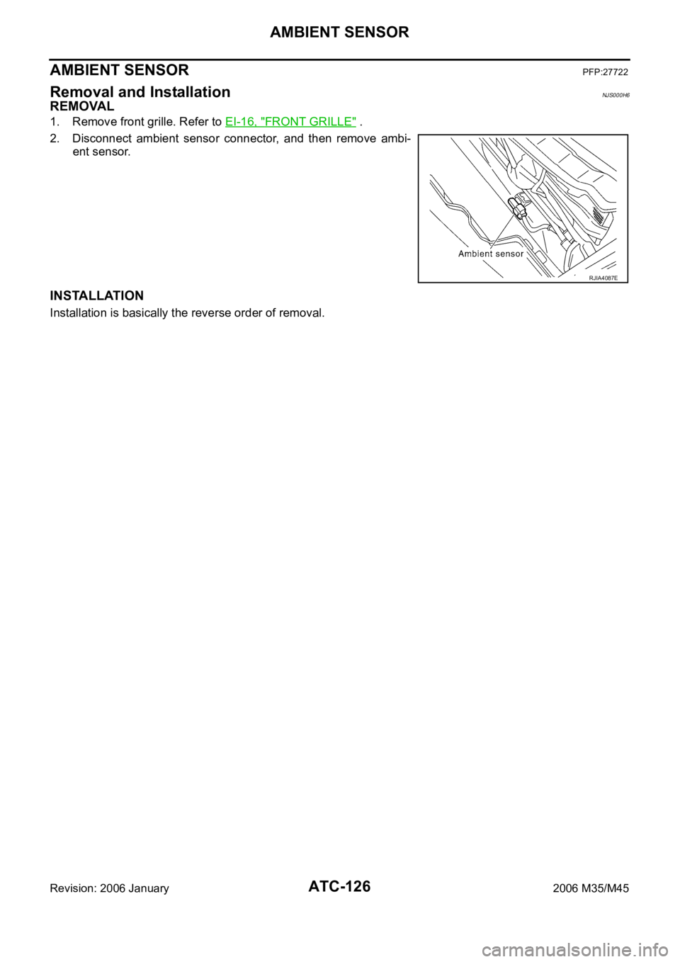
1. Remove front grille. Refer to EI-16, "FRONT GRILLE" .
2. Disconnect ambient sensor connector, and then remove ambi-
ent sensor.
INSTALLATION
Installation is basically the reverse order of removal.
RJIA4087E
Page 574 of 5621
IN-VEHICLE SENSOR
ATC-127
C
D
E
F
G
H
I
K
L
MA
B
AT C
Revision: 2006 January2006 M35/M45
IN-VEHICLE SENSORPFP:27720
Removal and InstallationNJS000H7
REMOVAL
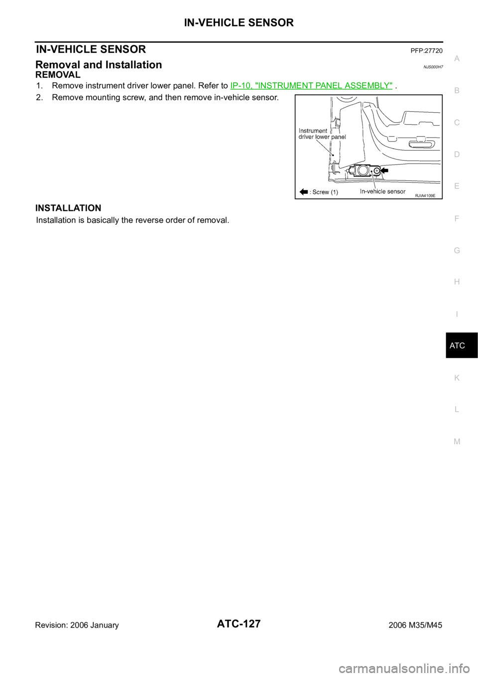
1. Remove instrument driver lower panel. Refer to IP-10, "INSTRUMENT PANEL ASSEMBLY" .
2. Remove mounting screw, and then remove in-vehicle sensor.
INSTALLATION
Installation is basically the reverse order of removal.
RJIA4109E
Page 575 of 5621
ATC-128
SUNLOAD SENSOR
Revision: 2006 January2006 M35/M45
SUNLOAD SENSORPFP:27721
Removal and InstallationNJS000H8
REMOVAL
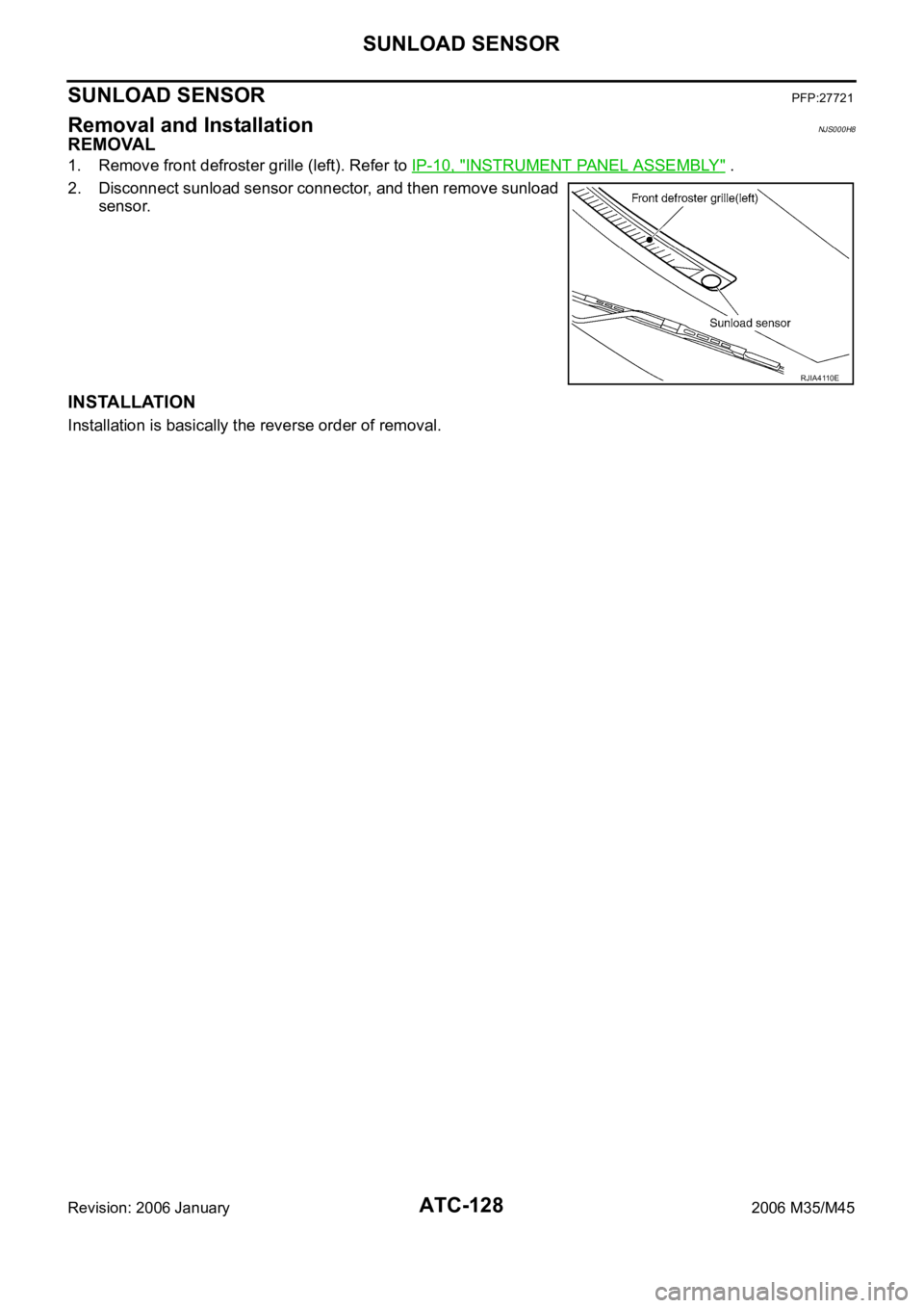
1. Remove front defroster grille (left). Refer to IP-10, "INSTRUMENT PANEL ASSEMBLY" .
2. Disconnect sunload sensor connector, and then remove sunload
sensor.
INSTALLATION
Installation is basically the reverse order of removal.
RJIA4110E
Page 576 of 5621
INTAKE SENSOR
ATC-129
C
D
E
F
G
H
I
K
L
MA
B
AT C
Revision: 2006 January2006 M35/M45
INTAKE SENSORPFP:27723
Removal and InstallationNJS000H9
REMOVAL
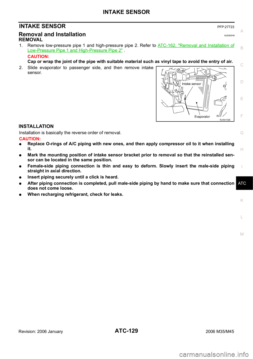
1. Remove low-pressure pipe 1 and high-pressure pipe 2. Refer to ATC-162, "Removal and Installation of
Low-Pressure Pipe 1 and High-Pressure Pipe 2" .
CAUTION:
Cap or wrap the joint of the pipe with suitable material such as vinyl tape to avoid the entry of air.
2. Slide evaporator to passenger side, and then remove intake
sensor.
INSTALLATION
Installation is basically the reverse order of removal.
CAUTION:
Replace O-rings of A/C piping with new ones, and then apply compressor oil to it when installing
it.
Mark the mounting position of intake sensor bracket prior to removal so that the reinstalled sen-
sor can be located in the same position.
Female-side piping connection is thin and easy to deform. Slowly insert the male-side piping
straight in axial direction.
Insert piping securely until a click is heard.
After piping connection is completed, pull male-side piping by hand to make sure that connection
does not come loose.
When recharging refrigerant, check for leaks.
RJIA4103E
Page 585 of 5621
ATC-138
HEATER & COOLING UNIT ASSEMBLY
Revision: 2006 January2006 M35/M45
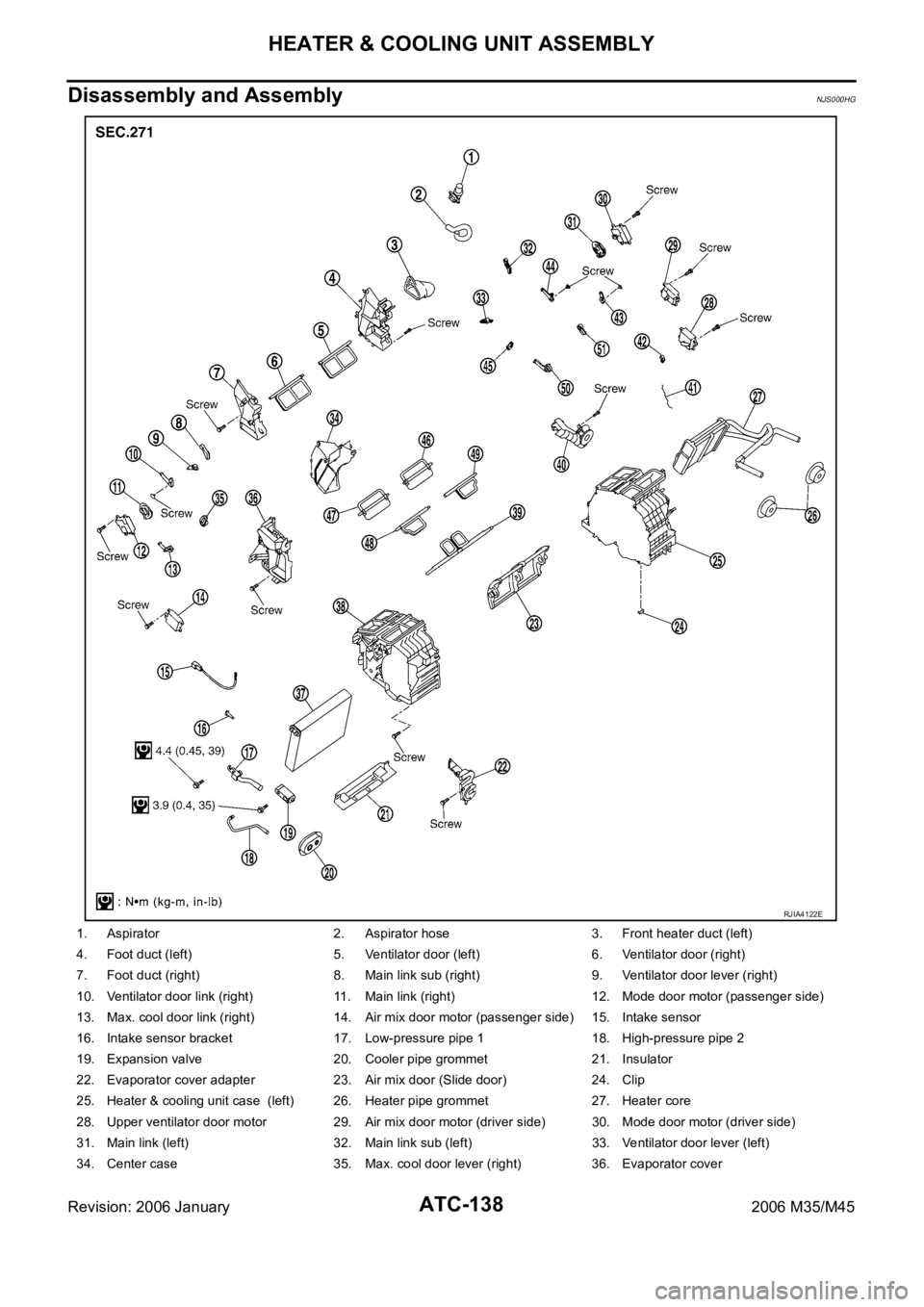
Disassembly and AssemblyNJS000HG
1. Aspirator 2. Aspirator hose 3. Front heater duct (left)
4. Foot duct (left) 5. Ventilator door (left) 6. Ventilator door (right)
7. Foot duct (right) 8. Main link sub (right) 9. Ventilator door lever (right)
10. Ventilator door link (right) 11. Main link (right) 12. Mode door motor (passenger side)
13. Max. cool door link (right) 14. Air mix door motor (passenger side) 15. Intake sensor
16. Intake sensor bracket 17. Low-pressure pipe 1 18. High-pressure pipe 2
19. Expansion valve 20. Cooler pipe grommet 21. Insulator
22. Evaporator cover adapter 23. Air mix door (Slide door) 24. Clip
25. Heater & cooling unit case (left) 26. Heater pipe grommet 27. Heater core
28. Upper ventilator door motor 29. Air mix door motor (driver side) 30. Mode door motor (driver side)
31. Main link (left) 32. Main link sub (left) 33. Ventilator door lever (left)
34. Center case 35. Max. cool door lever (right) 36. Evaporator cover
RJIA4122E
Page 611 of 5621
ATC-164
REFRIGERANT LINES
Revision: 2006 January2006 M35/M45
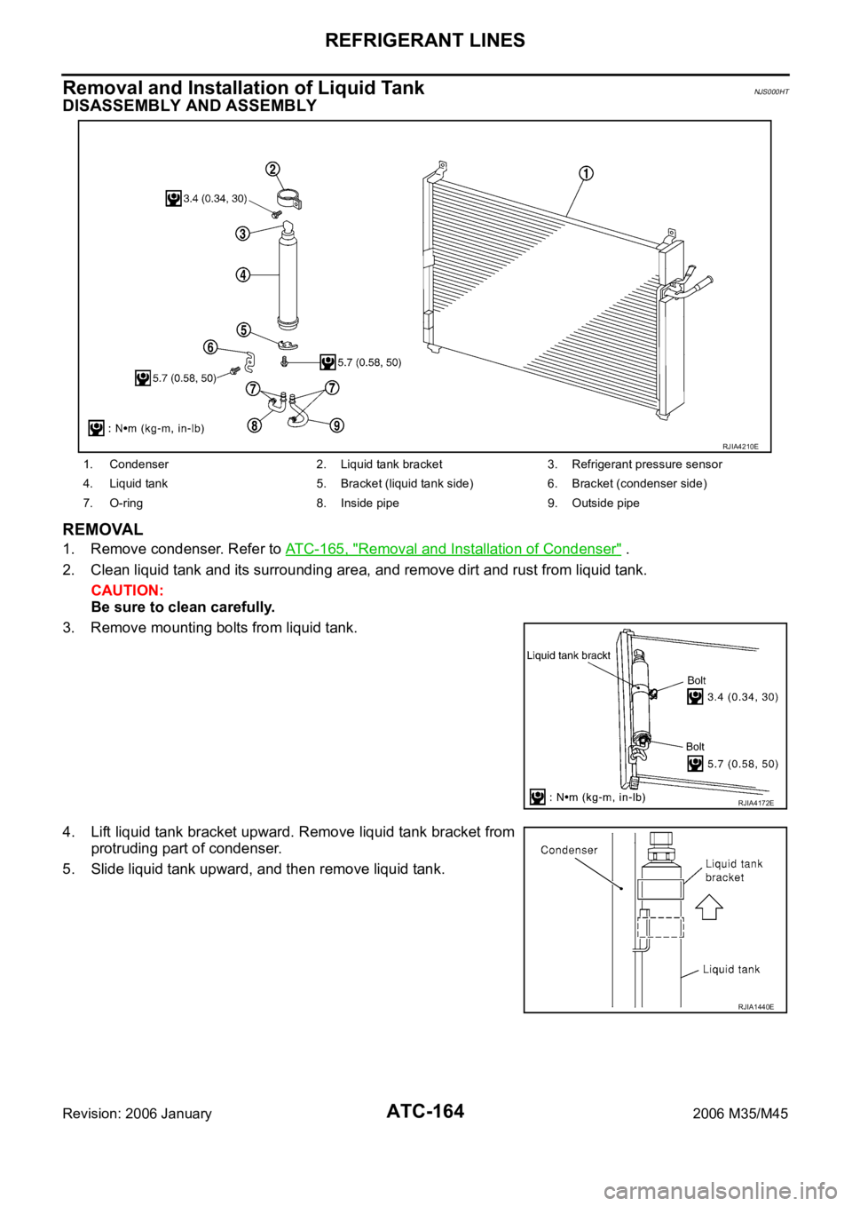
Removal and Installation of Liquid TankNJS000HT
DISASSEMBLY AND ASSEMBLY
REMOVAL
1. Remove condenser. Refer to ATC-165, "Removal and Installation of Condenser" .
2. Clean liquid tank and its surrounding area, and remove dirt and rust from liquid tank.
CAUTION:
Be sure to clean carefully.
3. Remove mounting bolts from liquid tank.
4. Lift liquid tank bracket upward. Remove liquid tank bracket from
protruding part of condenser.
5. Slide liquid tank upward, and then remove liquid tank.
1. Condenser 2. Liquid tank bracket 3. Refrigerant pressure sensor
4. Liquid tank 5. Bracket (liquid tank side) 6. Bracket (condenser side)
7. O-ring 8. Inside pipe 9. Outside pipe
RJIA4210E
RJIA4172E
RJIA1440E