INFINITI M35 2006 Factory Service Manual
M35 2006
INFINITI
INFINITI
https://www.carmanualsonline.info/img/42/57023/w960_57023-0.png
INFINITI M35 2006 Factory Service Manual
Page 5104 of 5621
PRE-CRASH SEAT BELT
SB-5
C
D
E
F
G
I
J
K
L
MA
B
SB
Revision: 2006 January2006 M35/M45
CAN Communication System DescriptionNHS0007Z
CAN (Controller Area Network) is a serial communication line for real time application. It is an on-vehicle mul-
tiplex communication line with high data communication speed and excellent error detection ability. Many elec-
tronic control units are equipped onto a vehicle, and each control unit shares information and links with other
control units during operation (not independent). In CAN communication, control units are connected with 2
communication lines (CAN H line, CAN L line) allowing a high rate of information transmission with less wiring.
Each control unit transmits/receives data but selectively reads required data only.
CAN Communication UnitNHS00080
Refer to LAN-34, "CAN Communication Unit" .
Page 5105 of 5621
SB-6
PRE-CRASH SEAT BELT
Revision: 2006 January2006 M35/M45
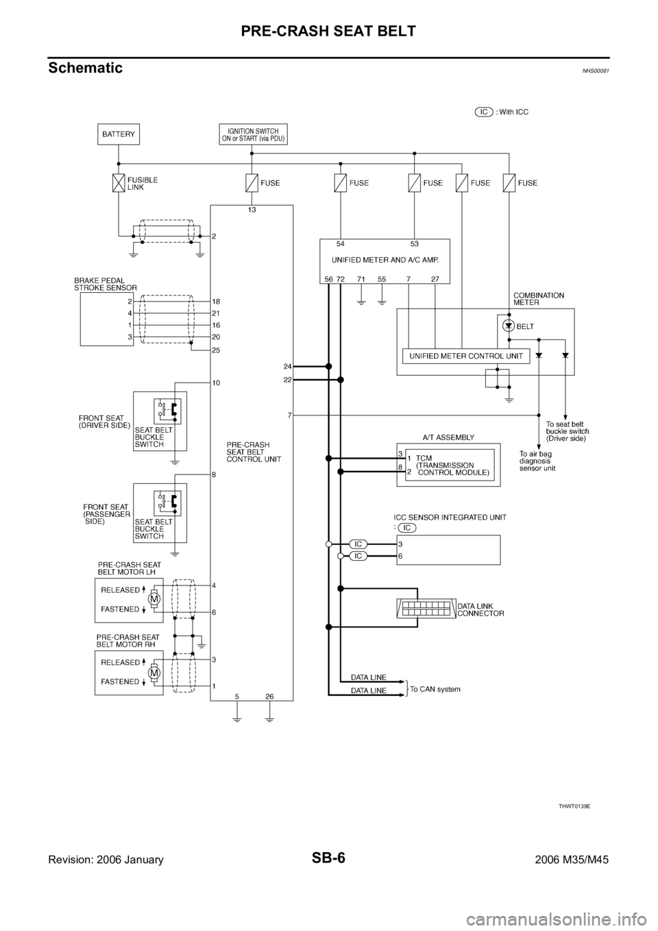
SchematicNHS00081
THWT0139E
Page 5106 of 5621
PRE-CRASH SEAT BELT
SB-7
C
D
E
F
G
I
J
K
L
MA
B
SB
Revision: 2006 January2006 M35/M45
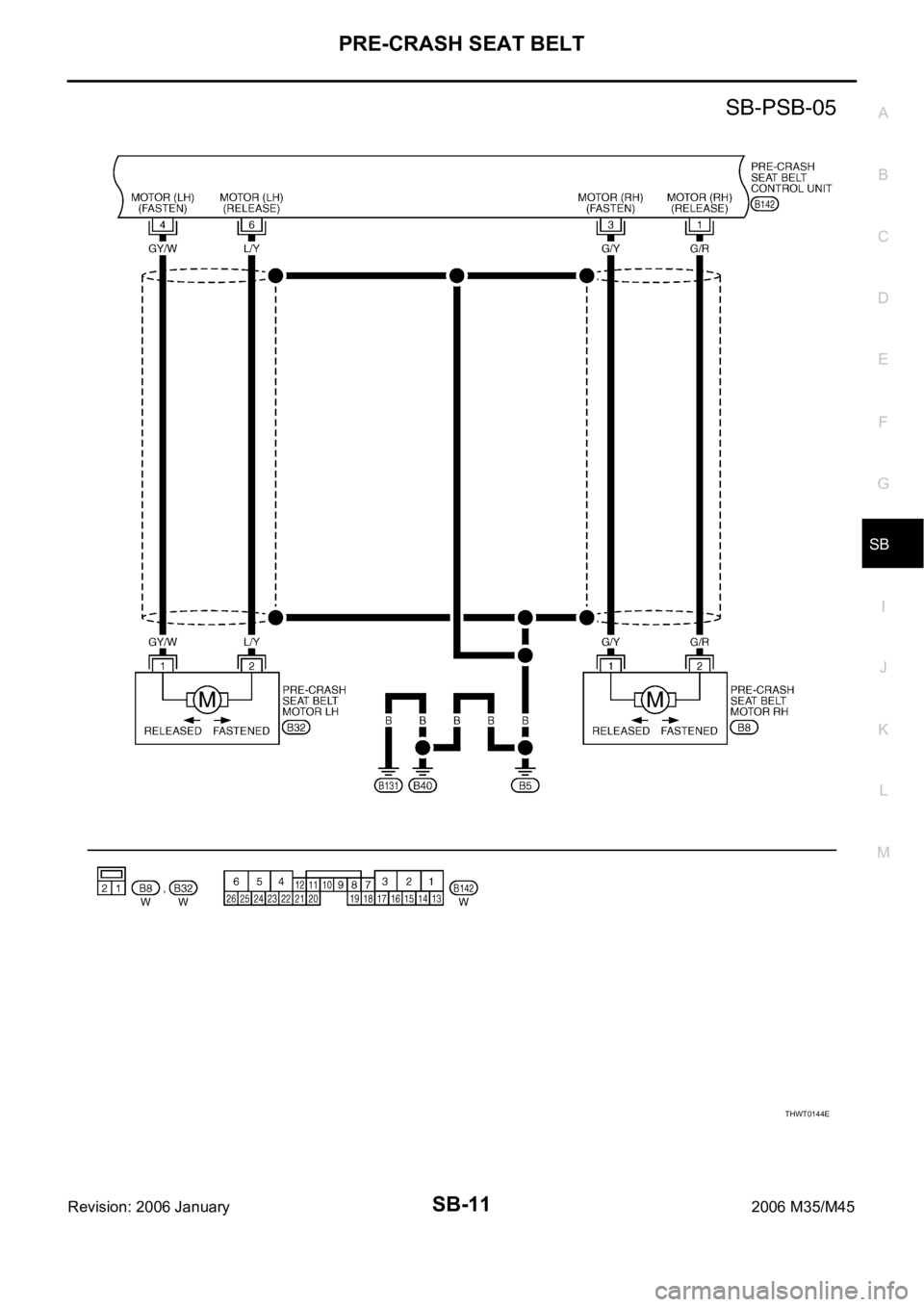
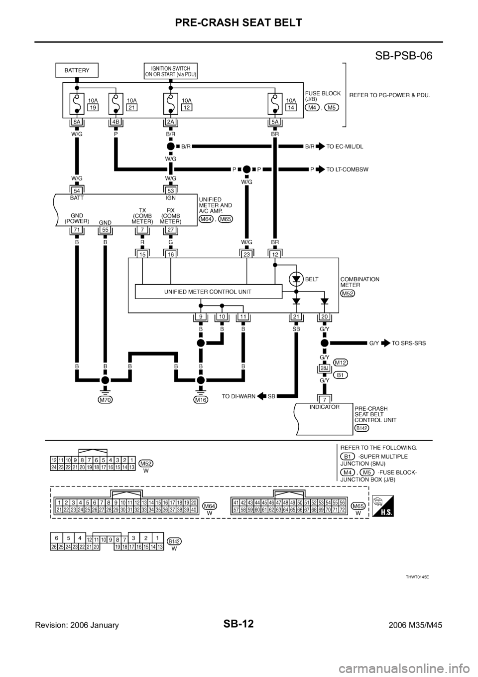
Wiring Diagram — PSB —NHS00082
THWT0140E
Page 5107 of 5621
SB-8
PRE-CRASH SEAT BELT
Revision: 2006 January2006 M35/M45
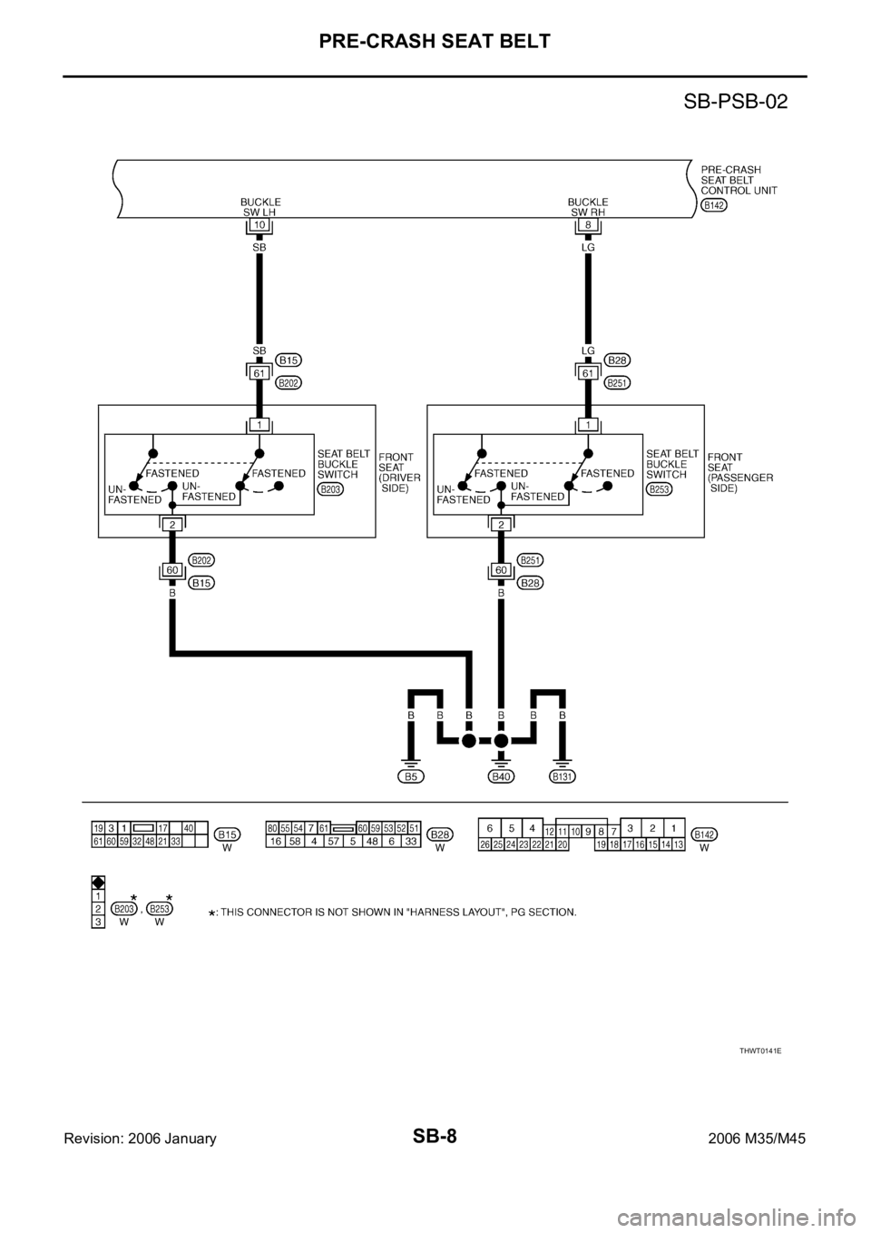
THWT0141E
Page 5108 of 5621
PRE-CRASH SEAT BELT
SB-9
C
D
E
F
G
I
J
K
L
MA
B
SB
Revision: 2006 January2006 M35/M45
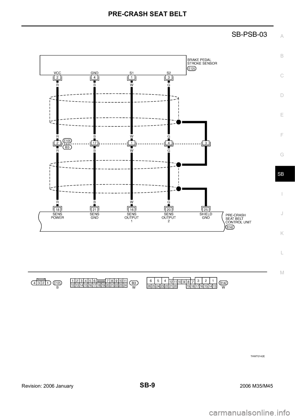
THWT0142E
Page 5109 of 5621
SB-10
PRE-CRASH SEAT BELT
Revision: 2006 January2006 M35/M45
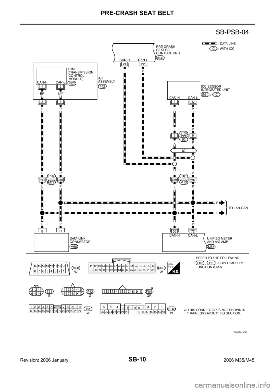
THWT0143E
Page 5110 of 5621
PRE-CRASH SEAT BELT
SB-11
C
D
E
F
G
I
J
K
L
MA
B
SB
Revision: 2006 January2006 M35/M45
THWT0144E
Page 5111 of 5621
SB-12
PRE-CRASH SEAT BELT
Revision: 2006 January2006 M35/M45
THWT0145E
Page 5112 of 5621

PRE-CRASH SEAT BELT
SB-13
C
D
E
F
G
I
J
K
L
MA
B
SB
Revision: 2006 January2006 M35/M45
Terminals and Reference Value for Pre-Crash Seat Belt Control UnitNHS00083
Work FlowNHS00084
1. Check the symptom and customer's requests.
2. Understand the system description. Refer to SB-3, "
System Description" .
3. Perform the preliminary check. Refer to SB-16, "
Preliminary Check" .
4. Check the self-diagnosis, results using CONSULT-II. Refer to SB-14, "
CONSULT-II Function (PRECRASH
SEATBELT)" .
5. Based on the trouble diagnosis chart, repair or replace the cause of the malfunction. Refer to SB-16,
"Diagnoses Symptom Chart" .
6. Does pre-crash seat belt system operate normally?
OK: GO TO 7.
NG: GO TO 4.
7. INSPECTION END
Terminal Wire Color Item ConditionVoltage [V]
(Approx.)
1G/RSeat belt motor RH release direction
signalSeat belt motor RH operation Battery voltage
Other than above 0
2 W Power source (BAT) – Battery voltage
3G/YSeat belt motor RH fastened direction
signalSeat belt motor RH operation Battery voltage
Other than above 0
4GY/WSeat belt motor LH fastened direction
signalSeat belt motor LH operation Battery voltage
Other than above 0
5 B/Y Ground (Driver circuit) – 0
6L/YSeat belt motor LH release direction
signalSeat belt motor LH operation Battery voltage
Other than above 0
7 G/Y Seat belt indicator signalWhen driver side seat belt is fastened Battery voltage
When driver side seat belt is un-fastened 0
When driver side seat belt is fastened and
system malfunctionBattery
voltage
0
8 LG Seat belt buckle switch RHWhen seat belt is fastened 5
When seat belt is un-fastened 0
10 SB Seat belt buckle switch LHWhen seat belt is fastened Battery voltage
When seat belt is un-fastened 0
13 W/G Power source (IGN) Ignition switch ON or START Battery voltage
16 WBrake pedal stroke sensor output sig-
nal 1Brake pedal is fully released operation 1
Brake pedal is slightly depressed operation 4
18 RPower source (Brake pedal stroke sen-
sor)
–5
20 GBrake pedal stroke sensor output sig-
nal 2Brake pedal is fully released operation 4
Brake pedal is slightly depressed operation 1
21 B Ground (Brake pedal stroke sensor) – 0
22 P CAN-L – -
24 L CAN-H – -
25 – Ground (Shield wire) – 0
26 B/Y Ground (Control circuit) – 0
Page 5113 of 5621

SB-14
PRE-CRASH SEAT BELT
Revision: 2006 January2006 M35/M45
CONSULT-II Function (PRECRASH SEATBELT)NHS00085
CONSULT-II can display each diagnostic item using the diagnostic test modes shown following.
CONSULT-II INSPECTION PROCEDURE
CAUTION:
If CONSULT-II is used with no connection of CONSULT-II CONVERTER, malfunctions might be
detected in self-diagnosis depending on control unit which carry out CAN communication.
1. Turn ignition switch “OFF”.
2. Connect “CONSULT-II” and “CONSULT-II CONVERTER” to the
data link connector (1).
3. Turn ignition switch “ON”.
4. Touch “START (NISSAN BASED VHCL)”.
5. Touch “PRECRASH SEATBELT”.
If “PRECRASH SEATBELT” is not indicated, refer to GI-40,
"CONSULT-II Data Link Connector (DLC) Circuit" .
CONSULT-II
diagnosis itemsInspection item
self-diagnosis modeContentReference
page
PRECRASH
SEATBELTSELF–DIAG RESULTS Carries out the self-diagnosis.SB-15
DATA MONITOR Displays pre-crash seat belt control unit input data in real time.SB-15
CAN DIAG SUPPORT MNTRThe results of transmit / receive diagnosis of CAN communication
can be read.LAN-20
ECU PART NUMBER Displays pre-crash seat belt control unit part No. –
PBIB2712E
BCIA0029E
BCIA0030E

