battery INFINITI M35 2006 Factory Owner's Guide
[x] Cancel search | Manufacturer: INFINITI, Model Year: 2006, Model line: M35, Model: INFINITI M35 2006Pages: 5621, PDF Size: 65.56 MB
Page 448 of 5621

ATC-1
AUTOMATIC AIR CONDITIONER
J AIR CONDITIONER
CONTENTS
C
D
E
F
G
H
I
K
L
M
SECTION AT C
A
B
AT C
Revision: 2006 January2006 M35/M45
AUTOMATIC AIR CONDITIONER
PRECAUTIONS .......................................................... 5
Precautions for Supplemental Restraint System
(SRS) “AIR BAG” and “SEAT BELT PRE-TEN-
SIONER” .................................................................. 5
Precautions Necessary for Steering Wheel Rotation
After Battery Disconnect .......................................... 5
OPERATION PROCEDURE ................................. 5
Precautions for Procedures without Cowl Top Cover ..... 6
Precautions for Working with HFC-134a (R-134a) ..... 6
CONTAMINATED REFRIGERANT ....................... 7
General Refrigerant Precautions .............................. 7
Precautions for Refrigerant Connection ................... 7
ABOUT ONE-TOUCH JOINT ................................ 7
FEATURES OF NEW TYPE REFRIGERANT
CONNECTION .................................................... 10
O-RING AND REFRIGERANT CONNECTION ... 10
Precautions for Servicing Compressor ................... 12
Precautions for Service Equipment ........................ 13
RECOVERY/RECYCLING EQUIPMENT ............ 13
ELECTRICAL LEAK DETECTOR ....................... 13
VACUUM PUMP ................................................. 13
MANIFOLD GAUGE SET .................................... 13
SERVICE HOSES ............................................... 14
SERVICE COUPLERS ........................................ 14
REFRIGERANT WEIGHT SCALE ...................... 14
CHARGING CYLINDER ...................................... 14
Precautions for Leak Detection Dye ....................... 15
IDENTIFICATION ................................................ 15
IDENTIFICATION LABEL FOR VEHICLE ........... 15
PREPARATION ......................................................... 16
Special Service Tools ............................................. 16
HFC-134a (R-134a) Service Tools and Equipment ... 17
Commercial Service Tools ...................................... 19
REFRIGERATION SYSTEM ..................................... 20
Refrigerant Cycle ................................................... 20
REFRIGERANT FLOW ....................................... 20
FREEZE PROTECTION ..................................... 20
Refrigerant System Protection ............................... 20
REFRIGERANT PRESSURE SENSOR ............. 20
PRESSURE RELIEF VALVE ............................... 20Variable Displacement Compressor ....................... 21
GENERAL INFORMATION ................................. 21
DESCRIPTION .................................................... 22
Component Layout ................................................. 25
LUBRICANT .............................................................. 26
Maintenance of Lubricant Quantity in Compressor ... 26
LUBRICANT ........................................................ 26
LUBRICANT RETURN OPERATION .................. 26
LUBRICANT ADJUSTING PROCEDURE FOR
COMPONENTS REPLACEMENT EXCEPT
COMPRESSOR .................................................. 27
LUBRICANT ADJUSTING PROCEDURE FOR
COMPRESSOR REPLACEMENT ....................... 27
AIR CONDITIONER CONTROL ............................... 29
Description of Air Conditioner LAN Control System ... 29
System Construction .............................................. 29
OPERATION ........................................................ 30
TRANSMISSION DATA AND TRANSMISSION
ORDER ............................................................... 30
AIR MIX DOOR CONTROL (AUTOMATIC TEM-
PERATURE CONTROL) ..................................... 31
FAN SPEED CONTROL ...................................... 31
INTAKE DOOR CONTROL ................................. 31
MODE DOOR CONTROL ................................... 31
UPPER VENTILATOR DOOR CONTROL .......... 31
MAGNET CLUTCH CONTROL ........................... 32
SELF-DIAGNOSIS SYSTEM .............................. 32
Description of Control System ................................ 33
Control Operation ................................................... 33
DISPLAY SCREEN .............................................. 33
MULTIFUNCTION SWITCH ................................ 34
DISPLAY SCREEN .............................................. 34
MODE SWITCH (DRIVER SIDE) ........................ 34
MODE SWITCH (PASSENGER SIDE) ................ 34
TEMPERATURE CONTROL SWITCH (POTEN-
TIO TEMPERATURE CONTROL) (DRIVER
SIDE) ................................................................... 34
TEMPERATURE CONTROL SWITCH (POTEN-
TIO TEMPERATURE CONTROL) (PASSEN-
GER SIDE) .......................................................... 34
Page 452 of 5621

PRECAUTIONS
ATC-5
C
D
E
F
G
H
I
K
L
MA
B
AT C
Revision: 2006 January2006 M35/M45
PRECAUTIONSPFP:00001
Precautions for Supplemental Restraint System (SRS) “AIR BAG” and “SEAT
BELT PRE-TENSIONER”
NJS000FN
The Supplemental Restraint System such as “AIR BAG” and “SEAT BELT PRE-TENSIONER”, used along
with a front seat belt, helps to reduce the risk or severity of injury to the driver and front passenger for certain
types of collision. This system includes seat belt switch inputs and dual stage front air bag modules. The SRS
system uses the seat belt switches to determine the front air bag deployment, and may only deploy one front
air bag, depending on the severity of a collision and whether the front occupants are belted or unbelted.
Information necessary to service the system safely is included in the SRS and SB section of this Service Man-
ual.
WAR NING :
To avoid rendering the SRS inoperative, which could increase the risk of personal injury or death
in the event of a collision which would result in air bag inflation, all maintenance must be per-
formed by an authorized NISSAN/INFINITI dealer.
Improper maintenance, including incorrect removal and installation of the SRS, can lead to per-
sonal injury caused by unintentional activation of the system. For removal of Spiral Cable and Air
Bag Module, see the SRS section.
Do not use electrical test equipment on any circuit related to the SRS unless instructed to in this
Service Manual. SRS wiring harnesses can be identified by yellow and/or orange harnesses or
harness connectors.
Precautions Necessary for Steering Wheel Rotation After Battery DisconnectNJS000FO
NOTE:
This Procedure is applied only to models with Intelligent Key system and NVIS/IVIS (NISSAN/INFINITI
VEHICLE IMMOBILIZER SYSTEM - NATS).
Remove and install all control units after disconnecting both battery cables with the ignition knob in the
LOCK position.
Always use CONSULT-II to perform self-diagnosis as a part of each function inspection after finishing
work. If DTC is detected, perform trouble diagnosis according to self-diagnostic results.
For models equipped with the Intelligent Key system and NVIS/IVIS, an electrically controlled steering lock
mechanism is adopted on the key cylinder.
For this reason, if the battery is disconnected or if the battery is discharged, the steering wheel will lock and
steering wheel rotation will become impossible.
If steering wheel rotation is required when battery power is interrupted, follow the procedure below before
starting the repair operation.
OPERATION PROCEDURE
1. Connect both battery cables.
NOTE:
Supply power using jumper cables if battery is discharged.
2. Use the Intelligent Key or mechanical key to turn the ignition switch to the
ACC position. At this time, the
steering lock will be released.
3. Disconnect both battery cables. The steering lock will remain released and the steering wheel can be
rotated.
4. Perform the necessary repair operation.
5. When the repair work is completed, return the ignition switch to the
LOCK position before connecting
the battery cables. (At this time, the steering lock mechanism will engage.)
6. Perform a self-diagnosis check of all control units using CONSULT-II.
Page 464 of 5621

PREPARATION
ATC-17
C
D
E
F
G
H
I
K
L
MA
B
AT C
Revision: 2006 January2006 M35/M45
HFC-134a (R-134a) Service Tools and EquipmentNJS000FX
Never mix HFC-134a (R-134a) refrigerant and/or its specified lubricant with CFC-12 (R-12) refrigerant and/or
its lubricant.
Separate and non-interchangeable service equipment must be used for handling each type of refrigerant/lubri-
cant.
Refrigerant container fittings, service hose fittings and service equipment fittings (equipment which handles
refrigerant and/or lubricant) are different between CFC-12 (R-12) and HFC-134a (R-134a). This is to avoid
mixed use of the refrigerants/lubricant.
Never use adapters that convert one size fitting to another: refrigerant/lubricant contamination occurs and
compressor malfunction may result.
Tool number
(Kent-Moore No.)
Tool nameDescription
HFC-134a (R-134a) refrigerantContainer color: Light blue
Container marking: HFC-134a (R-
134a)
Fitting size: Thread size
Large container 1/2 -16 ACME
Nissan A/C System Oil Type S
(DH-PS)Type: Polyalkylene glycol oil (PAG),
type S (DH-PS)
Application: HFC-134a (R-134a)
swash plate compressors (Nissan
only)
Capacity: 40 m (1.4 US fl oz., 1.4
Imp fl oz.)
(ACR2005-NI)
ACR5 A/C Service CenterFunction: Refrigerant recovery,
recycling and recharging
(J-41995)
Electrical A/C leak detectorPower supply:
DC 12 V (Battery terminal)
S-NT196
S-NT197
WJIA0293E
AHA281A
Page 465 of 5621

ATC-18
PREPARATION
Revision: 2006 January2006 M35/M45
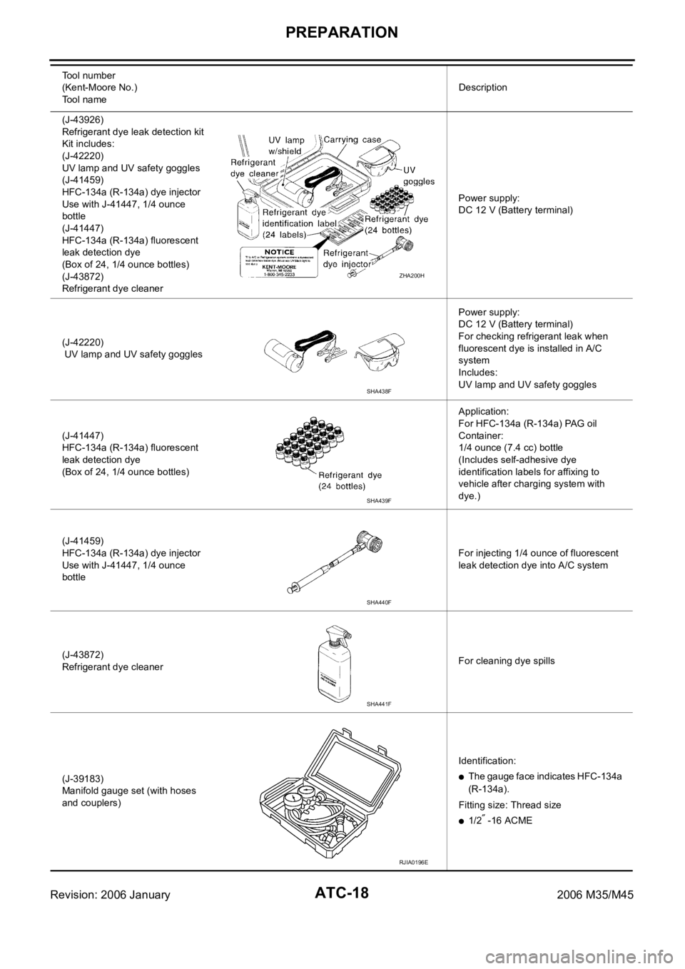
(J-43926)
Refrigerant dye leak detection kit
Kit includes:
(J-42220)
UV lamp and UV safety goggles
(J-41459)
HFC-134a (R-134a) dye injector
Use with J-41447, 1/4 ounce
bottle
(J-41447)
HFC-134a (R-134a) fluorescent
leak detection dye
(Box of 24, 1/4 ounce bottles)
(J-43872)
Refrigerant dye cleanerPower supply:
DC 12 V (Battery terminal)
(J-42220)
UV lamp and UV safety gogglesPower supply:
DC 12 V (Battery terminal)
For checking refrigerant leak when
fluorescent dye is installed in A/C
system
Includes:
UV lamp and UV safety goggles
(J-41447)
HFC-134a (R-134a) fluorescent
leak detection dye
(Box of 24, 1/4 ounce bottles)Application:
For HFC-134a (R-134a) PAG oil
Container:
1/4 ounce (7.4 cc) bottle
(Includes self-adhesive dye
identification labels for affixing to
vehicle after charging system with
dye.)
(J-41459)
HFC-134a (R-134a) dye injector
Use with J-41447, 1/4 ounce
bottleFor injecting 1/4 ounce of fluorescent
leak detection dye into A/C system
(J-43872)
Refrigerant dye cleanerFor cleaning dye spills
(J-39183)
Manifold gauge set (with hoses
and couplers)Identification:
The gauge face indicates HFC-134a
(R-134a).
Fitting size: Thread size
1/2 -16 ACME Tool number
(Kent-Moore No.)
Tool nameDescription
ZHA200H
SHA438F
SHA439F
SHA440F
SHA441F
RJIA0196E
Page 500 of 5621

TROUBLE DIAGNOSIS
ATC-53
C
D
E
F
G
H
I
K
L
MA
B
AT C
Revision: 2006 January2006 M35/M45
Auto Amp. Terminals and Reference ValueNJS000GI
Measure voltage between each terminal and ground by referring ter-
minals and reference value for unified meter and A/C amp.
PIN CONNECTOR TERMINAL LAYOUT
TERMINALS AND REFERENCE VALUE FOR UNIFIED METER AND A/C AMP.
RJIA4032E
RJIA4033E
Terminal
No.Wire
colorItemIgnition
switchConditionVoltage
(V)
38 L/Y Blower motor control signal ON Blower speed: 1st step
41 V Power supply from ACC ACC — Battery voltage
43 R Intake sensor — — —
44 GR In-vehicle sensor — — —
45 W/V Ambient sensor — — —
46 BR/Y Sunload sensor — — —
53 W/G Power supply from IGN ON — Battery voltage
54 W/G Power supply from BATT OFF — Battery voltage
55 B Ground ON — Approx. 0
56 L CAN-H — — —
59 O/B Intake sensor ground ON — Approx. 0
60 P In-vehicle sensor ground ON — Approx. 0
61 LG/R Ambient sensor ground ON — Approx. 0
62 V/R Sunload sensor ground ON — Approx. 0
SJIA1454J
Page 501 of 5621

ATC-54
TROUBLE DIAGNOSIS
Revision: 2006 January2006 M35/M45
65 OECV (Electric Control Valve)
signalONSelf-diagnosis. STEP-4
(Code No. 45)
69 R A/C LAN signal ON —
70 WPower supply for each door
motorON — Battery voltage
71 B Ground (Power) ON — Approx. 0
72 P CAN-L — — — Te r m i n a l
No.Wire
colorItemIgnition
switchConditionVoltag e
(V)
SJIA1458J
SJIA1453J
Page 503 of 5621

ATC-56
TROUBLE DIAGNOSIS
Revision: 2006 January2006 M35/M45
FUNCTION CONFIRMATION PROCEDURE
1. SET IN SELF-DIAGNOSIS MODE
1. Turn ignition switch ON.
2. Set in self-diagnosis mode as follows. Within 10 seconds after starting engine (ignition switch is turned
ON.), press OFF switch for at least 5 seconds.
CAUTION:
If battery voltage drops below 12 V during diagnosis STEP-3, door motor speed becomes slower
and as a result, the system may generate an error even when operation is normal. To avoid this,
start engine before performing this diagnosis.
Former STEP-1 (LEDs and display screen are checked) does not exist in this self-diagnosis func-
tion.
>> GO TO 2.
2. STEP-2: SENSOR CIRCUITS ARE CHECKED FOR OPEN OR SHORT CIRCUIT
Does code No. 20 appear on the display?
YES >> GO TO 3.
NO >> GO TO 13.
3. CHECK TO ADVANCE SELF-DIAGNOSIS STEP-3
Press temperature control (UP) switch (driver side).
Advance to self
-diagnosis STEP-3?
YES >> GO TO 4.
NO >> Replace Multifunction switch. (Temperature control switch is malfunctioning.)
4. CHECK TO RETURN SELF-DIAGNOSIS STEP-2
Press temperature control (DOWN) switch (driver side).
Return to self
-diagnosis STEP-2?
YES >> GO TO 5.
NO >> Malfunctioning multifunction switch or unified meter and A/C amp. Refer to AT C - 111 , "
Self-Diag-
nosis" .
5. STEP-3: MODE DOOR AND INTAKE DOOR POSITIONS ARE CHECKED
Press temperature control (UP) switch (driver side).
Does code No. 30 appear on the display?
YES >> GO TO 6.
NO >> GO TO 14.
RJIA0219E
RJIA0220E
Page 509 of 5621

ATC-62
TROUBLE DIAGNOSIS
Revision: 2006 January2006 M35/M45
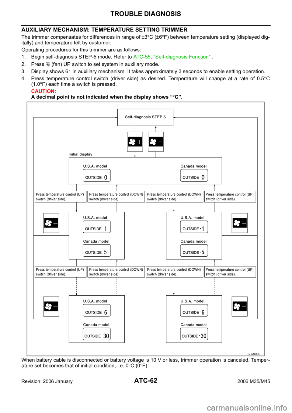
AUXILIARY MECHANISM: TEMPERATURE SETTING TRIMMER
The trimmer compensates for differences in range of 3C (6F) between temperature setting (displayed dig-
itally) and temperature felt by customer.
Operating procedures for this trimmer are as follows:
1. Begin self-diagnosis STEP-5 mode. Refer to ATC-55, "
Self-diagnosis Function" .
2. Press (fan) UP switch to set system in auxiliary mode.
3. Display shows 61 in auxiliary mechanism. It takes approximately 3 seconds to enable setting operation.
4. Press temperature control switch (driver side) as desired. Temperature will change at a rate of 0.5
C
(1.0
F) each time a switch is pressed.
CAUTION:
A decimal point is not indicated when the display shows “
C”.
When battery cable is disconnected or battery voltage is 10 V or less, trimmer operation is canceled. Temper-
ature set becomes that of initial condition, i.e. 0
C (0F).
SJIA1693E
Page 510 of 5621

TROUBLE DIAGNOSIS
ATC-63
C
D
E
F
G
H
I
K
L
MA
B
AT C
Revision: 2006 January2006 M35/M45
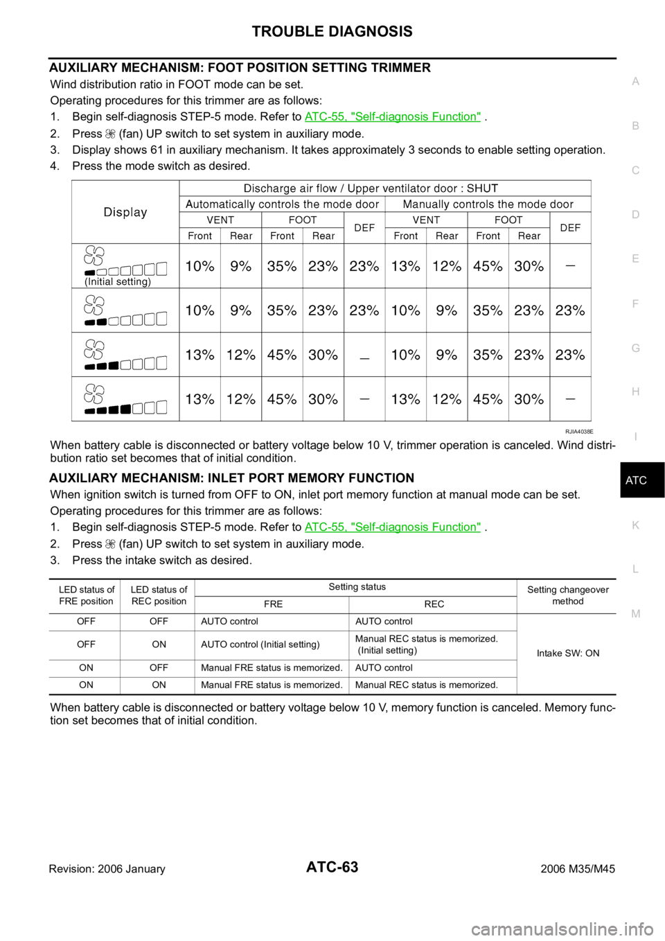
AUXILIARY MECHANISM: FOOT POSITION SETTING TRIMMER
Wind distribution ratio in FOOT mode can be set.
Operating procedures for this trimmer are as follows:
1. Begin self-diagnosis STEP-5 mode. Refer to AT C - 5 5 , "
Self-diagnosis Function" .
2. Press (fan) UP switch to set system in auxiliary mode.
3. Display shows 61 in auxiliary mechanism. It takes approximately 3 seconds to enable setting operation.
4. Press the mode switch as desired.
When battery cable is disconnected or battery voltage below 10 V, trimmer operation is canceled. Wind distri-
bution ratio set becomes that of initial condition.
AUXILIARY MECHANISM: INLET PORT MEMORY FUNCTION
When ignition switch is turned from OFF to ON, inlet port memory function at manual mode can be set.
Operating procedures for this trimmer are as follows:
1. Begin self-diagnosis STEP-5 mode. Refer to AT C - 5 5 , "
Self-diagnosis Function" .
2. Press (fan) UP switch to set system in auxiliary mode.
3. Press the intake switch as desired.
When battery cable is disconnected or battery voltage below 10 V, memory function is canceled. Memory func-
tion set becomes that of initial condition.
RJIA4038E
LED status o f
FRE positionLED status of
REC positionSetting status
Setting changeover
method
FRE REC
OFF OFF AUTO control AUTO control
Intake SW: ON OFF ON AUTO control (Initial setting)Manual REC status is memorized.
(Initial setting)
ON OFF Manual FRE status is memorized. AUTO control
ON ON Manual FRE status is memorized. Manual REC status is memorized.
Page 515 of 5621

ATC-68
TROUBLE DIAGNOSIS
Revision: 2006 January2006 M35/M45
1. CHECK POWER SUPPLY CIRCUIT FOR UNIFIED METER AND A/C AMP.
1. Disconnect unified meter and A/C amp. connector.
2. Check voltage between unified meter and A/C amp. harness
connector M65 terminals 41, 53 and 55 and ground.
OK or NG
OK >> GO TO 2.
NG >> Check 10A fuses [Nos. 6, 12 and 19, located in the fuse block (J/B)]. Refer to P G - 111 , "
FUSE
BLOCK - JUNCTION BOX (J/B)" .
If fuses are OK, check harness for open circuit. Repair or replace if necessary.
If fuses are NG, check harness for short circuit and replace fuse.
2. CHECK GROUND CIRCUIT FOR UNIFIED METER AND A/C AMP.
1. Turn ignition switch OFF.
2. Check continuity between unified meter and A/C amp. harness
connector M65 terminal 55, 71 and ground.
OK or NG
OK >> Replace unified meter and A/C amp.
NG >> Repair harness or connector.
Terminals Ignition switch position
(+)
(-) OFF ACC ON Unified
meter and
A/C amp.
connectorTerminal
No.
M65 41
GroundApprox. 0 VBattery
voltageBattery
voltage
M65 53 Approx. 0 V Approx. 0 VBattery
voltage
M65 54Battery
voltageBattery
voltageBattery
voltage
RJIA4050E
55, 71 – Ground : Continuity should exist.
RJIA4051E