battery INFINITI M35 2006 Factory User Guide
[x] Cancel search | Manufacturer: INFINITI, Model Year: 2006, Model line: M35, Model: INFINITI M35 2006Pages: 5621, PDF Size: 65.56 MB
Page 120 of 5621
ON BOARD DIAGNOSTIC (OBD) SYSTEM
AT-41
D
E
F
G
H
I
J
K
L
MA
B
AT
Revision: 2006 January2006 M35/M45
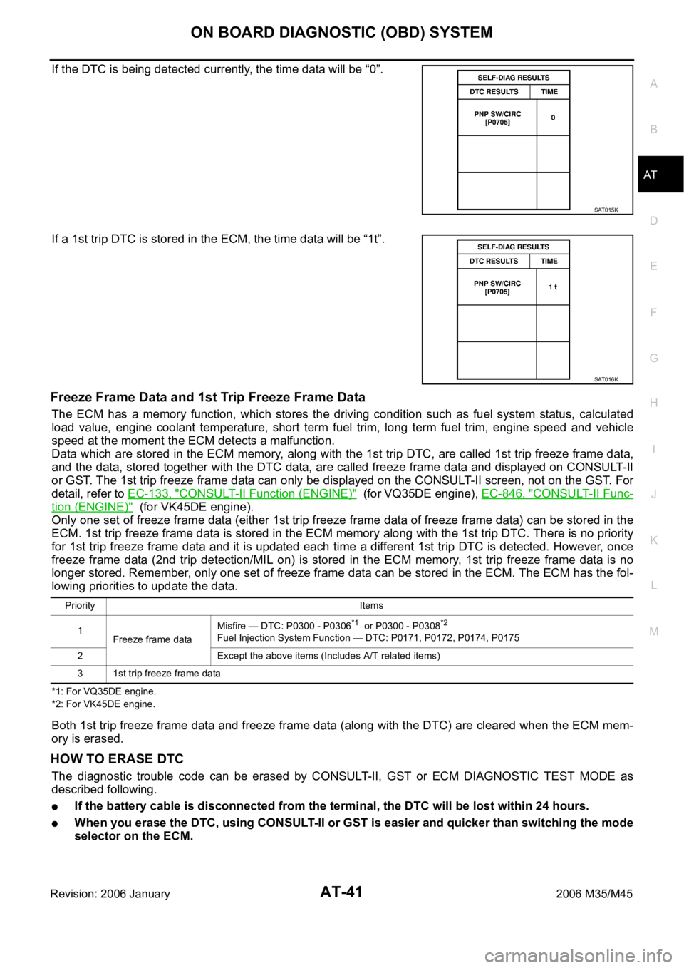
If the DTC is being detected currently, the time data will be “0”.
If a 1st trip DTC is stored in the ECM, the time data will be “1t”.
Freeze Frame Data and 1st Trip Freeze Frame Data
The ECM has a memory function, which stores the driving condition such as fuel system status, calculated
load value, engine coolant temperature, short term fuel trim, long term fuel trim, engine speed and vehicle
speed at the moment the ECM detects a malfunction.
Data which are stored in the ECM memory, along with the 1st trip DTC, are called 1st trip freeze frame data,
and the data, stored together with the DTC data, are called freeze frame data and displayed on CONSULT-II
or GST. The 1st trip freeze frame data can only be displayed on the CONSULT-II screen, not on the GST. For
detail, refer to EC-133, "
CONSULT-II Function (ENGINE)" (for VQ35DE engine), EC-846, "CONSULT-II Func-
tion (ENGINE)" (for VK45DE engine).
Only one set of freeze frame data (either 1st trip freeze frame data of freeze frame data) can be stored in the
ECM. 1st trip freeze frame data is stored in the ECM memory along with the 1st trip DTC. There is no priority
for 1st trip freeze frame data and it is updated each time a different 1st trip DTC is detected. However, once
freeze frame data (2nd trip detection/MIL on) is stored in the ECM memory, 1st trip freeze frame data is no
longer stored. Remember, only one set of freeze frame data can be stored in the ECM. The ECM has the fol-
lowing priorities to update the data.
*1: For VQ35DE engine.
*2: For VK45DE engine.
Both 1st trip freeze frame data and freeze frame data (along with the DTC) are cleared when the ECM mem-
ory is erased.
HOW TO ERASE DTC
The diagnostic trouble code can be erased by CONSULT-II, GST or ECM DIAGNOSTIC TEST MODE as
described following.
If the battery cable is disconnected from the terminal, the DTC will be lost within 24 hours.
When you erase the DTC, using CONSULT-II or GST is easier and quicker than switching the mode
selector on the ECM.
SAT015K
SAT016K
Priority Items
1
Freeze frame dataMisfire — DTC: P0300 - P0306
*1 or P0300 - P0308*2
Fuel Injection System Function — DTC: P0171, P0172, P0174, P0175
2 Except the above items (Includes A/T related items)
3 1st trip freeze frame data
Page 168 of 5621

TROUBLE DIAGNOSIS
AT-89
D
E
F
G
H
I
J
K
L
MA
B
AT
Revision: 2006 January2006 M35/M45
TCM Input/Output Signal Reference ValuesNCS001KG
A/T ASSEMBLY HARNESS CONNECTOR TERMINAL LAYOUT
TCM INSPECTION TABLE
Data are reference value and are measured between each terminal and ground.
SCIA1658E
TerminalWire
colorItem Condition Data (Approx.)
1R/WPower supply
(Memory back-up)Always Battery voltage
2R/WPower supply
(Memory back-up)Always Battery voltage
3 L CAN-H – –
4VK-line (CONSULT-
II signal)The terminal is connected to the data link connector for CONSULT-II. –
5 B Ground Always 0V
6 Y/R Power supply– Battery voltage
–0V
7R/LBack-up lamp
relaySelector lever in “R” position. 0V
Selector lever in other positions. Battery voltage
8 P CAN-L – –
9 GR/R Starter relaySelector lever in “N”, “P” positions. Battery voltage
Selector lever in “R”, “D” positions. 0V
10 B Ground Always 0V
Page 176 of 5621
TROUBLE DIAGNOSIS
AT-97
D
E
F
G
H
I
J
K
L
MA
B
AT
Revision: 2006 January2006 M35/M45
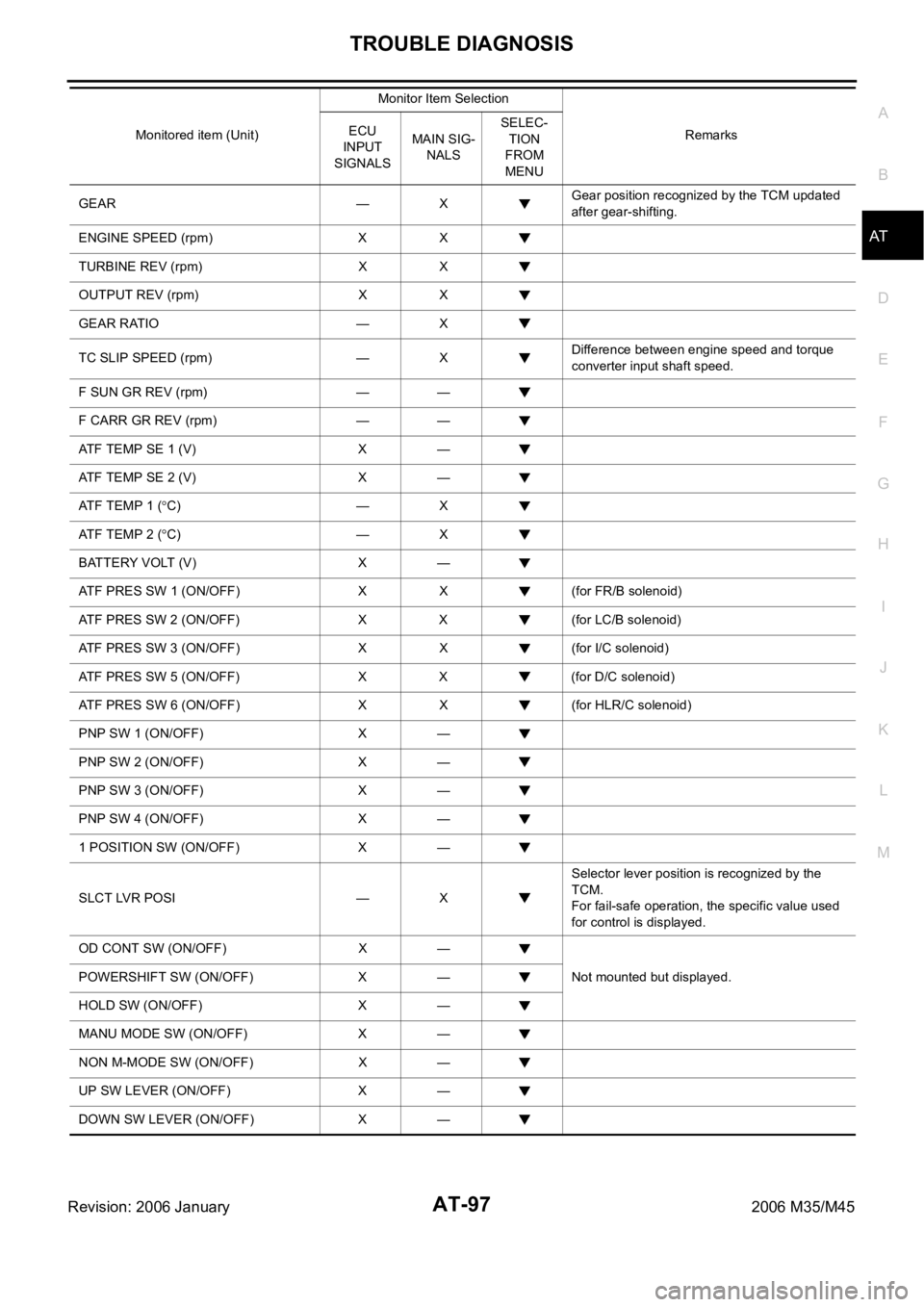
GEAR — XGear position recognized by the TCM updated
after gear-shifting.
ENGINE SPEED (rpm) X X
TURBINE REV (rpm) X X
OUTPUT REV (rpm) X X
GEAR RATIO — X
TC SLIP SPEED (rpm) — XDifference between engine speed and torque
converter input shaft speed.
F SUN GR REV (rpm) — —
F CARR GR REV (rpm) — —
ATF TEMP SE 1 (V) X —
ATF TEMP SE 2 (V) X —
ATF TEMP 1 (
C) — X
ATF TEMP 2 (
C) — X
BATTERY VOLT (V) X —
ATF PRES SW 1 (ON/OFF) X X (for FR/B solenoid)
ATF PRES SW 2 (ON/OFF) X X (for LC/B solenoid)
ATF PRES SW 3 (ON/OFF) X X (for I/C solenoid)
ATF PRES SW 5 (ON/OFF) X X (for D/C solenoid)
ATF PRES SW 6 (ON/OFF) X X (for HLR/C solenoid)
PNP SW 1 (ON/OFF) X —
PNP SW 2 (ON/OFF) X —
PNP SW 3 (ON/OFF) X —
PNP SW 4 (ON/OFF) X —
1 POSITION SW (ON/OFF) X —
SLCT LVR POSI — XSelector lever position is recognized by the
TCM.
For fail-safe operation, the specific value used
for control is displayed.
OD CONT SW (ON/OFF) X —
Not mounted but displayed. POWERSHIFT SW (ON/OFF) X —
HOLD SW (ON/OFF) X —
MANU MODE SW (ON/OFF) X —
NON M-MODE SW (ON/OFF) X —
UP SW LEVER (ON/OFF) X —
DOWN SW LEVER (ON/OFF) X —Monitored item (Unit)Monitor Item Selection
Remarks ECU
INPUT
SIGNALSMAIN SIG-
NALSSELEC-
TION
FROM
MENU
Page 189 of 5621

AT-110
DTC P0615 START SIGNAL CIRCUIT
Revision: 2006 January2006 M35/M45
TCM terminals and data are reference value. Measured between each terminal and ground.
Diagnostic ProcedureNCS001KV
1. CHECK STARTER RELAY
With CONSULT-II
1. Turn ignition switch ON. (Do not start engine.)
2. Select “SELECTION FROM MENU” in “DATA MONITOR” mode
for “A/T” with CONSULT-II and check monitor “STARTER
RELAY” ON/OFF.
Without CONSULT-II
1. Turn ignition switch ON. (Do not start engine.)
2. Check voltage between the IPDM E/R connector and ground.
OK or NG
OK >> GO TO 5.
NG >> GO TO 2.
2. CHECK HARNESS BETWEEN A/T ASSEMBLY HARNESS CONNECTOR AND IPDM E/R CONNEC-
TOR
1. Turn ignition switch OFF.
2. Disconnect A/T assembly harness connector and IPDM E/R connector.
3. Check continuity between A/T assembly harness connector and
IPDM E/R connector.
4. If OK, check harness for short to ground and short to power.
5. Reinstall any part removed.
OK or NG
OK >> GO TO 3.
NG >> Repair open circuit or short to ground or short to power in harness or connectors.
Terminal Item Condition Data (Approx.)
9 Starter relaySelector lever in “N”, “P” positions. Battery voltage
Selector lever in “R”, “D” positions. 0V
Item name Condition Display value
STARTER RELAYSelector lever in “N”, “P” positions. ON
Selector lever in “R”, “D” positions. OFF
Item Connector Terminal Shift position Voltage (Approx.)
Starter
relayE9 53 Ground“N”, “P” Battery voltage
“R”, “D” 0V
PCIA0056E
SCIA2103E
Item Connector Terminal Continuity
A/T assembly harness con-
nectorF42 9
Ye s
IPDM E/R connector E9 53
SCIA5439E
Page 249 of 5621

AT-170
DTC P1815 MANUAL MODE SWITCH
Revision: 2006 January2006 M35/M45
TCM terminals and data are reference value. Measured between each terminal and ground.
Diagnostic ProcedureNCS001OZ
1. CHECK CAN COMMUNICATION LINE
Perform the self-diagnosis. Refer to AT- 9 2 , "
SELF-DIAGNOSTIC RESULT MODE" .
Is a malfunction in the CAN communication indicated in the results?
YES >> Check CAN communication line. Refer to AT- 1 0 5 , "DTC U1000 CAN COMMUNICATION LINE" .
NO >> GO TO 2.
2. CHECK MANUAL MODE SWITCH CIRCUIT
With CONSULT-II
1. Turn ignition switch ON. (Do not start engine.)
2. Select “ECU INPUT SIGNALS” in “DATA MONITOR” mode for
“A/T” with CONSULT-II.
3. Read out ON/OFF switching action of “MANU MODE SW”,
“NON M-MODE SW”, “UP SW LEVER”, “DOWN SW LEVER”.
Without CONSULT-II
Drive vehicle in the manual mode, and confirm that the actual gear position and the meter's indication of the
position mutually coincide when the selector lever is shifted to the “+ (up)” or “- (down)” side (1st
5th gear).
OK or NG
OK >> GO TO 4.
NG >> GO TO 3.
3. DETECT MALFUNCTIONING ITEM
Check the following.
Manual mode switch. Refer to AT-171, "Component Inspection" .
Pin terminals for damage or loose connection with harness connector.
Open circuit or short to ground or short to power in harness or connector for A/T device (manual mode
switch).
Unified meter and A/C amp. Refer to DI-5, "COMBINATION METERS" .
OK or NG
OK >> GO TO 4.
NG >> Repair or replace damaged parts.
Terminal Item Condition Data (Approx.)
3CAN-H – –
8CAN-L – –
9 Starter relaySelector lever in “N”, “P” positions. Battery voltage
Selector lever in “R”, “D” positions. 0V
Item name Condition Display Value
MANU MODE SWManual shift gate position (neutral) ON
Other than the above OFF
NON M-MODE SWManual shift gate position OFF
Other than the above ON
UP SW LEVERSelector lever: +side ON
Other than the above OFF
DOWN SW LEVERSelector lever: -side ON
Other than the above OFF
SCIA4988E
Page 260 of 5621

MAIN POWER SUPPLY AND GROUND CIRCUIT
AT-181
D
E
F
G
H
I
J
K
L
MA
B
AT
Revision: 2006 January2006 M35/M45
TCM terminals and data are reference value. Measured between each terminal and ground.
Diagnostic ProcedureNCS001PQ
1. CHECK TCM POWER SOURCE STEP 1
1. Turn ignition switch OFF.
2. Disconnect A/T assembly harness connector.
3. Check voltage between A/T assembly harness connector termi-
nals and ground.
OK or NG
OK >> GO TO 2.
NG >> GO TO 3.
2. CHECK TCM POWER SOURCE STEP 2
1. Disconnect A/T assembly harness connector.
2. Turn ignition switch ON. (Do not start engine.)
3. Check voltage between A/T assembly harness connector termi-
nals and ground.
OK or NG
OK >> GO TO 4.
NG >> GO TO 3.
Terminal Item Condition Data (Approx.)
1Power supply
(Memory back-up)Always Battery voltage
2Power supply
(Memory back-up)Always Battery voltage
5 Ground Always 0V
6 Power supply– Battery voltage
–0V
10 Ground Always 0V
Item Connector Terminal Voltage
TCM F421 - Ground
Battery voltage
2 - Ground
6 - Ground 0V
SCIA2104E
Item Connector Terminal Voltage
TCM F421 - Ground
Battery voltage 2 - Ground
6 - Ground
SCIA2105E
Page 261 of 5621

AT-182
MAIN POWER SUPPLY AND GROUND CIRCUIT
Revision: 2006 January2006 M35/M45
3. DETECT MALFUNCTIONING ITEM
Check the following.
Harness for short or open between battery and A/T assembly harness connector terminals 1, 2
Harness for short or open between push-button ignition switch and A/T assembly harness connector ter-
minal 6
10A fuse (No. 34, located in the fuse and fusible link block) and 10A fuse (No. 83, located in the IPDM E/
R)
Push-button ignition switch (Refer to PG-3, "POWER SUPPLY ROUTING CIRCUIT" )
OK or NG
OK >> GO TO 4.
NG >> Repair or replace damaged parts.
4. CHECK TCM GROUND CIRCUIT
1. Turn ignition switch OFF.
2. Disconnect A/T assembly harness connector.
3. Check continuity between A/T assembly harness connector ter-
minals and ground.
If OK, check harness for short to ground and short to power.
OK or NG
OK >> GO TO 5.
NG >> Repair open circuit or short to ground or short to power
in harness or connectors.
5. DETECT MALFUNCTIONING ITEM
Check the following.
The A/T assembly harness connector terminals for damage or loose connection with harness connector.
OK or NG
OK >> GO TO 6.
NG >> Repair or replace damaged parts.
6. PERFORM SELF-DIAGNOSIS
Perform self-diagnosis. Refer to AT- 9 2 , "
SELF-DIAGNOSTIC RESULT MODE" .
OK or NG
OK >>INSPECTION END
NG-1 >> Self-diagnosis does not activate: GO TO 7.
NG-2 >> DTC is displayed: Check the malfunctioning system. Refer to AT- 9 2 , "
SELF-DIAGNOSTIC
RESULT MODE" . Continuity should exist.
SCIA2106E
Page 264 of 5621

BRAKE SIGNAL CIRCUIT
AT-185
D
E
F
G
H
I
J
K
L
MA
B
AT
Revision: 2006 January2006 M35/M45
BRAKE SIGNAL CIRCUITPFP:25320
CONSULT-II Reference ValueNCS001PT
Diagnostic ProcedureNCS001PU
1. CHECK CAN COMMUNICATION LINE
Perform the self-diagnosis. Refer to AT- 9 2 , "
SELF-DIAGNOSTIC RESULT MODE" , AT- 1 0 3 , "Diagnostic Pro-
cedure without CONSULT-II" .
Is a malfunction in the CAN communication indicated in the results?
YES >> Check CAN communication line. Refer to AT-105, "DTC U1000 CAN COMMUNICATION LINE" .
NO >> GO TO 2.
2. CHECK STOP LAMP SWITCH CIRCUIT
With CONSULT-II
1. Turn ignition switch ON. (Do not start engine.)
2. Select “ECU INPUT SIGNALS” in “DATA MONITOR” mode for
“A/T” with CONSULT-II.
3. Read out ON/OFF switching action of the “BRAKE SW”.
OK or NG
OK >>INSPECTION END
NG >> GO TO 3.
3. CHECK STOP LAMP SWITCH
Check continuity between stop lamp switch harness connector termi-
nals. Refer to AT-187, "
Wiring Diagram — AT — NONDTC" .
Check stop lamp switch after adjusting brake pedal — refer to
BR-6, "
BRAKE PEDAL" .
OK or NG
OK >> Check the following. If NG, repair or replace damaged
parts.
Harness for short or open between battery and stop lamp switch.
Harness for short or open between stop lamp switch and unified meter and A/C amp.
10A fuse (No.20, located in fuse block).
NG >> Repair or replace the stop lamp switch.
Item name Condition Display value
BRAKE SWDepressed brake pedal. ON
Released brake pedal. OFF
Item name Condition Display value
BRAKE SWDepressed brake pedal. ON
Released brake pedal. OFF
PCIA0070E
Condition Continuity
When brake pedal is depressed Yes
When brake pedal is released No
SCIA4782E
Page 269 of 5621

AT-190
TROUBLE DIAGNOSIS FOR SYMPTOMS
Revision: 2006 January2006 M35/M45
TCM terminals and data are reference value. Measured between each terminal and ground.
A/T CHECK Indicator Lamp Does Not Come OnNCS001PZ
SYMPTOM:
A/T CHECK indicator lamp does not come on for about 2 seconds when turning ignition switch to ON.
DIAGNOSTIC PROCEDURE
1. CHECK CAN COMMUNICATION LINE
Perform self-diagnosis. Refer to AT- 9 2 , "
SELF-DIAGNOSTIC RESULT MODE" , AT- 1 0 3 , "TCM SELF-DIAG-
NOSTIC PROCEDURE (NO TOOLS)" .
Is a malfunction in the CAN communication indicated in the results?
YES >> Check CAN communication line. Refer to AT- 1 0 5 , "DTC U1000 CAN COMMUNICATION LINE" .
NO >> GO TO 2.
2. CHECK A/T CHECK INDICATOR LAMP CIRCUIT
Check combination meters. Refer to DI-5, "
COMBINATION METERS" .
OK or NG
OK >> GO TO 3
NG >> Repair or replace damaged parts.
3. CHECK TCM POWER SUPPLY AND GROUND CIRCUIT
Check TCM power supply and ground circuit. Refer to AT- 1 8 0 , "
MAIN POWER SUPPLY AND GROUND CIR-
CUIT" .
OK or NG
OK >>INSPECTION END
NG >> Repair or replace damaged parts.
Engine Cannot Be Started in “P” or “N” PositionNCS001Q0
SYMPTOM:
Engine cannot be started with selector lever in “P” or “N” position.
Engine can be started with selector lever in “D”or “R” position.
DIAGNOSTIC PROCEDURE
1. CHECK PNP SWITCH CIRCUIT
Perform self-diagnosis. Refer to AT- 9 2 , "
SELF-DIAGNOSTIC RESULT MODE" , AT- 1 0 3 , "TCM SELF-DIAG-
NOSTIC PROCEDURE (NO TOOLS)" .
Do the self-diagnostic results indicate PNP switch?
YES >> Check malfunctioning system. Refer to AT- 11 3 , "DTC P0705 PARK/NEUTRAL POSITION
SWITCH" .
NO >> GO TO 2.
Terminal Item Condition Data (Approx.)
3CAN-H – –
4K-line (CONSULT-II
signal)The terminal is connected to the data link connector for CONSULT- I I. –
7 Back-up lamp relaySelector lever in “R” position. 0V
Selector lever in other positions. Battery voltage
8CAN-L – –
Page 311 of 5621

AT-232
A/T SHIFT LOCK SYSTEM
Revision: 2006 January2006 M35/M45
Diagnostic ProcedureNCS001QS
SYMPTOM:
Selector lever cannot be moved from “P” position with key in ON position and brake pedal
applied.
Selector lever can be moved from “P” position with key in ON position and brake pedal released.
1. CHECK SELECTOR LEVER POSITION
Check the selector lever position for damage. Refer to AT- 2 2 8 , "
Checking of A/T Position" .
OK or NG
OK >> GO TO 2.
NG >> Adjust control linkage. Refer to AT-227, "
Adjustment of A/T Position" .
2. CHECK POWER SOURCE
1. Turn ignition switch OFF.
2. Disconnect shift lock relay.
3. Check voltage between shift lock relay E35 terminal 2 and
ground.
OK or NG
OK >> GO TO 4.
NG >> GO TO 3.Vo l ta g e
Brake pedal depressed: Battery voltage
Brake pedal released: 0V
SCIA6866E