ECO mode INFINITI M35 2006 Factory Service Manual
[x] Cancel search | Manufacturer: INFINITI, Model Year: 2006, Model line: M35, Model: INFINITI M35 2006Pages: 5621, PDF Size: 65.56 MB
Page 4851 of 5621
PG-24
IPDM E/R (INTELLIGENT POWER DISTRIBUTION MODULE ENGINE ROOM)
Revision: 2006 January2006 M35/M45
Auto Active TestNKS004E7
DESCRIPTION
In auto active test mode, operation inspection can be performed when IPDM E/R sends a drive signal to the
following systems:
Rear window defogger
Front wiper (LO, HI)
Tail lamps, parking lamps and license plate lamps
Front fog lamps
Headlamps (LO, HI)
A/C compressor (magnetic clutch)
Cooling fan
Oil pressure warning lamp
OPERATION PROCEDURE
1. Close hood and front door (passenger side), and then lift wiper arms away from windshield (to prevent
glass damage by wiper operation).
NOTE:
When auto active test is performed with hood opened, sprinkle water on windshield beforehand.
2. Turn ignition switch OFF.
3. Turn ignition switch ON, and within 20 seconds, press driver's door switch 10 times (close other doors).
Then turn ignition switch OFF.
4. Turn ignition switch ON within 10 seconds after ignition switch OFF.
5. When auto active test mode is actuated, horn chirps once. Oil pressure warning lamp starts blinking.
6. After a series of operations is repeated three times, auto active test is completed.
NOTE:
When auto active test mode has to be cancelled halfway, turn ignition switch OFF.
CAUTION:
Never start the engine.
If the engine starting operation is made, delete DTC on the self-diag results of CONSULT-II.
Refer to BL-81, "
CONSULT-II Application Items" .
Be sure to inspect GW-52, "Door Switch Check" when the auto active test cannot be performed.
Page 4852 of 5621
IPDM E/R (INTELLIGENT POWER DISTRIBUTION MODULE ENGINE ROOM)
PG-25
C
D
E
F
G
H
I
J
L
MA
B
PG
Revision: 2006 January2006 M35/M45
INSPECTION IN AUTO ACTIVE TEST MODE
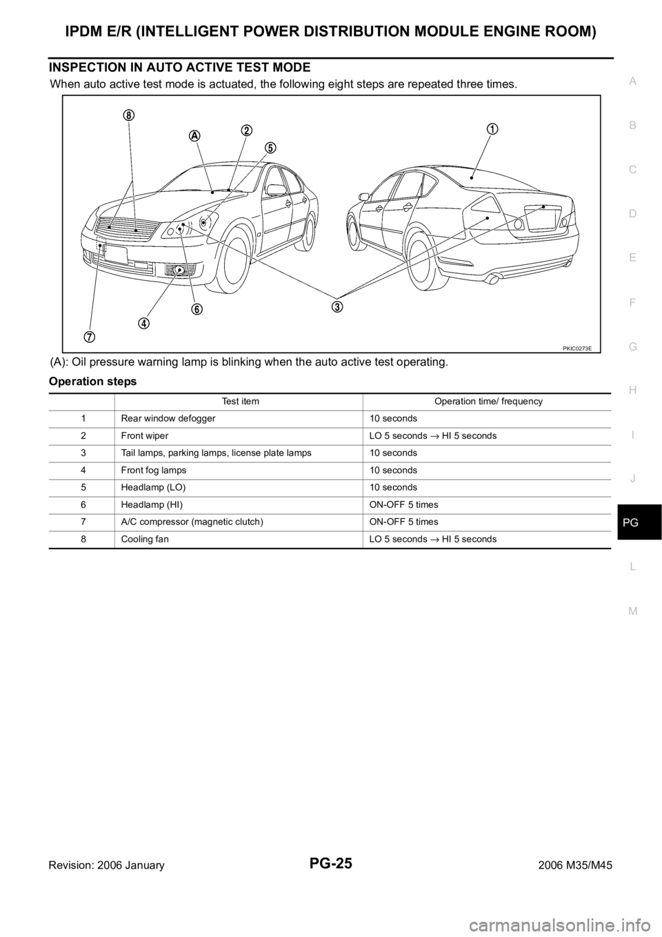
When auto active test mode is actuated, the following eight steps are repeated three times.
(A): Oil pressure warning lamp is blinking when the auto active test operating.
Operation steps
PKIC0273E
Test item Operation time/ frequency
1 Rear window defogger 10 seconds
2 Front wiper LO 5 seconds
HI 5 seconds
3 Tail lamps, parking lamps, license plate lamps 10 seconds
4 Front fog lamps 10 seconds
5 Headlamp (LO) 10 seconds
6 Headlamp (HI) ON-OFF 5 times
7 A/C compressor (magnetic clutch) ON-OFF 5 times
8 Cooling fan LO 5 seconds
HI 5 seconds
Page 4870 of 5621
PDU (POWER DISTRIBUTION UNIT)
PG-43
C
D
E
F
G
H
I
J
L
MA
B
PG
Revision: 2006 January2006 M35/M45
3. PUSH-BUTTON IGNITION SWITCH INDICATOR GROUND CIRCUIT
1. Disconnect Intelligent Key unit connector.
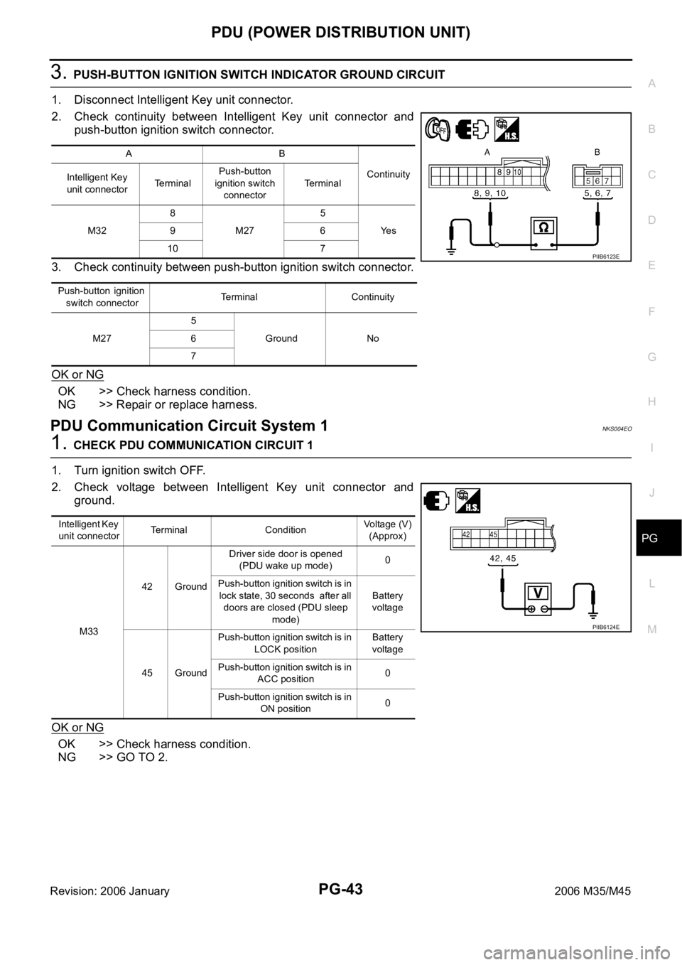
2. Check continuity between Intelligent Key unit connector and
push-button ignition switch connector.
3. Check continuity between push-button ignition switch connector.
OK or NG
OK >> Check harness condition.
NG >> Repair or replace harness.
PDU Communication Circuit System 1NKS004EO
1. CHECK PDU COMMUNICATION CIRCUIT 1
1. Turn ignition switch OFF.
2. Check voltage between Intelligent Key unit connector and
ground.
OK or NG
OK >> Check harness condition.
NG >> GO TO 2.
AB
Continuity
Intelligent Key
unit connectorTerminalPush-button
ignition switch
connectorTe r m i n a l
M328
M275
Ye s 96
10 7
P u s h - b u t t o n i g n i t i o n
switch connectorTerminal Continuity
M275
Ground No 6
7
PIIB6123E
Intelligent Key
unit connectorTerminal ConditionVoltage (V)
(Approx)
M3342 GroundDriver side door is opened
(PDU wake up mode)0
Push-button ignition switch is in
lock state, 30 seconds after all
doors are closed (PDU sleep
mode)Battery
voltage
45 GroundPush-button ignition switch is in
LOCK positionBattery
voltage
Push-button ignition switch is in
ACC position0
Push-button ignition switch is in
ON position0
PIIB6124E
Page 4982 of 5621
POWER STEERING OIL PUMP
PS-29
C
D
E
F
H
I
J
K
L
MA
B
PS
Revision: 2006 January2006 M35/M45
POWER STEERING OIL PUMPPFP:49110
On-Vehicle Inspection and ServiceNGS000DE
CHECKING RELIEF OIL PRESSURE
CAUTION:
Make sure that belt tension is normal before starting the following procedure.
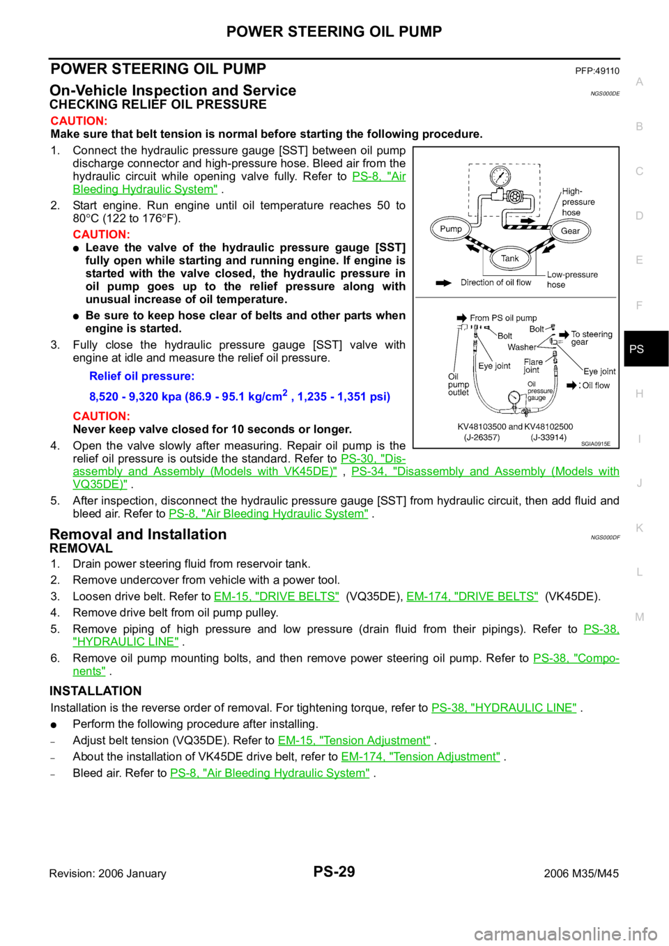
1. Connect the hydraulic pressure gauge [SST] between oil pump
discharge connector and high-pressure hose. Bleed air from the
hydraulic circuit while opening valve fully. Refer to PS-8, "
Air
Bleeding Hydraulic System" .
2. Start engine. Run engine until oil temperature reaches 50 to
80
C (122 to 176F).
CAUTION:
Leave the valve of the hydraulic pressure gauge [SST]
fully open while starting and running engine. If engine is
started with the valve closed, the hydraulic pressure in
oil pump goes up to the relief pressure along with
unusual increase of oil temperature.
Be sure to keep hose clear of belts and other parts when
engine is started.
3. Fully close the hydraulic pressure gauge [SST] valve with
engine at idle and measure the relief oil pressure.
CAUTION:
Never keep valve closed for 10 seconds or longer.
4. Open the valve slowly after measuring. Repair oil pump is the
relief oil pressure is outside the standard. Refer to PS-30, "
Dis-
assembly and Assembly (Models with VK45DE)" , PS-34, "Disassembly and Assembly (Models with
VQ35DE)" .
5. After inspection, disconnect the hydraulic pressure gauge [SST] from hydraulic circuit, then add fluid and
bleed air. Refer to PS-8, "
Air Bleeding Hydraulic System" .
Removal and InstallationNGS000DF
REMOVAL
1. Drain power steering fluid from reservoir tank.
2. Remove undercover from vehicle with a power tool.
3. Loosen drive belt. Refer to EM-15, "
DRIVE BELTS" (VQ35DE), EM-174, "DRIVE BELTS" (VK45DE).
4. Remove drive belt from oil pump pulley.
5. Remove piping of high pressure and low pressure (drain fluid from their pipings). Refer to PS-38,
"HYDRAULIC LINE" .
6. Remove oil pump mounting bolts, and then remove power steering oil pump. Refer to PS-38, "
Compo-
nents" .
INSTALLATION
Installation is the reverse order of removal. For tightening torque, refer to PS-38, "HYDRAULIC LINE" .
Perform the following procedure after installing.
–Adjust belt tension (VQ35DE). Refer to EM-15, "Tension Adjustment" .
–About the installation of VK45DE drive belt, refer to EM-174, "Tension Adjustment" .
–Bleed air. Refer to PS-8, "Air Bleeding Hydraulic System" . Relief oil pressure:
8,520 - 9,320 kpa (86.9 - 95.1 kg/cm
2 , 1,235 - 1,351 psi)
SGIA0915E
Page 5054 of 5621
FRONT OIL SEAL
RFD-11
C
E
F
G
H
I
J
K
L
MA
B
RFD
Revision: 2006 January2006 M35/M45
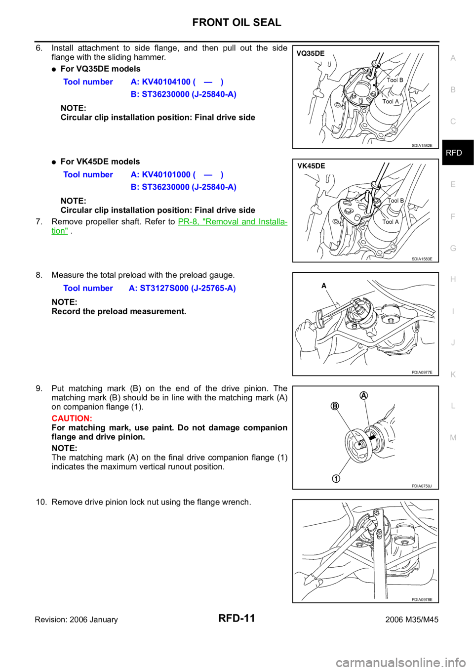
6. Install attachment to side flange, and then pull out the side
flange with the sliding hammer.
For VQ35DE models
NOTE:
Circular clip installation position: Final drive side
For VK45DE models
NOTE:
Circular clip installation position: Final drive side
7. Remove propeller shaft. Refer to PR-8, "
Removal and Installa-
tion" .
8. Measure the total preload with the preload gauge.
NOTE:
Record the preload measurement.
9. Put matching mark (B) on the end of the drive pinion. The
matching mark (B) should be in line with the matching mark (A)
on companion flange (1).
CAUTION:
For matching mark, use paint. Do not damage companion
flange and drive pinion.
NOTE:
The matching mark (A) on the final drive companion flange (1)
indicates the maximum vertical runout position.
10. Remove drive pinion lock nut using the flange wrench.Tool number A: KV40104100 ( — )
B: ST36230000 (J-25840-A)
SDIA1582E
Tool number A: KV40101000 ( — )
B: ST36230000 (J-25840-A)
SDIA1583E
Tool number A: ST3127S000 (J-25765-A)
PDIA0977E
PDIA0750J
PDIA0978E
Page 5057 of 5621
RFD-14
SIDE OIL SEAL
Revision: 2006 January2006 M35/M45
SIDE OIL SEALPFP:33142
Removal and InstallationNDS000F6
REMOVAL
1. Remove center muffler with a power tool. Refer to EX-3, "EXHAUST SYSTEM" .
2. Remove rear wheel sensor. Refer to BRC-57, "
WHEEL SENSOR" .
3. Remove drive shaft from final drive with a power tool. Then suspend it by wire etc. Refer to RAX-8, "
REAR
DRIVE SHAFT" .
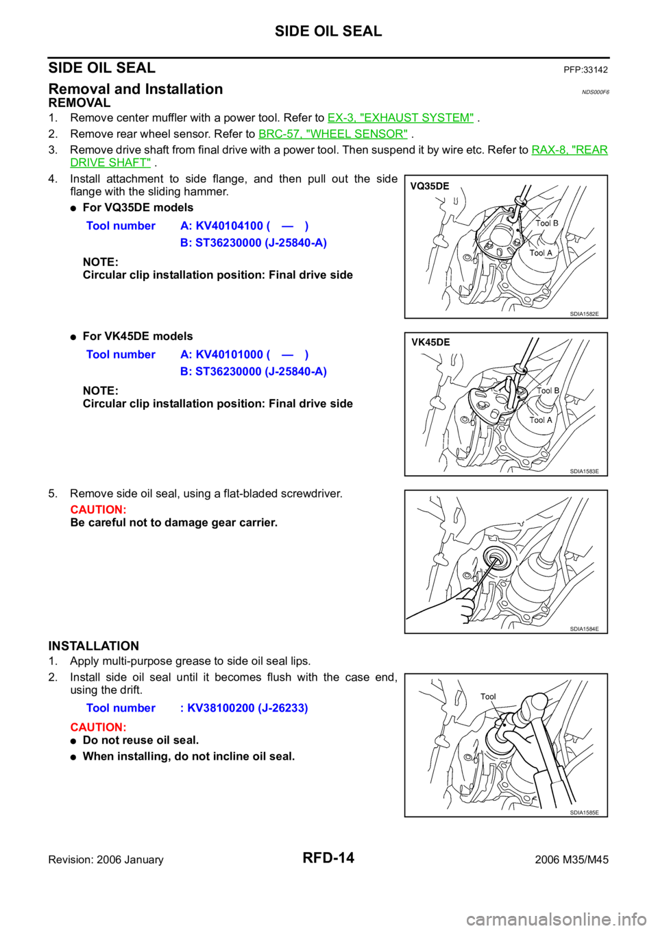
4. Install attachment to side flange, and then pull out the side
flange with the sliding hammer.
For VQ35DE models
NOTE:
Circular clip installation position: Final drive side
For VK45DE models
NOTE:
Circular clip installation position: Final drive side
5. Remove side oil seal, using a flat-bladed screwdriver.
CAUTION:
Be careful not to damage gear carrier.
INSTALLATION
1. Apply multi-purpose grease to side oil seal lips.
2. Install side oil seal until it becomes flush with the case end,
using the drift.
CAUTION:
Do not reuse oil seal.
When installing, do not incline oil seal.Tool number A: KV40104100 ( — )
B: ST36230000 (J-25840-A)
SDIA1582E
Tool number A: KV40101000 ( — )
B: ST36230000 (J-25840-A)
SDIA1583E
SDIA1584E
Tool number : KV38100200 (J-26233)
SDIA1585E
Page 5113 of 5621

SB-14
PRE-CRASH SEAT BELT
Revision: 2006 January2006 M35/M45
CONSULT-II Function (PRECRASH SEATBELT)NHS00085
CONSULT-II can display each diagnostic item using the diagnostic test modes shown following.
CONSULT-II INSPECTION PROCEDURE
CAUTION:
If CONSULT-II is used with no connection of CONSULT-II CONVERTER, malfunctions might be
detected in self-diagnosis depending on control unit which carry out CAN communication.
1. Turn ignition switch “OFF”.
2. Connect “CONSULT-II” and “CONSULT-II CONVERTER” to the
data link connector (1).
3. Turn ignition switch “ON”.
4. Touch “START (NISSAN BASED VHCL)”.
5. Touch “PRECRASH SEATBELT”.
If “PRECRASH SEATBELT” is not indicated, refer to GI-40,
"CONSULT-II Data Link Connector (DLC) Circuit" .
CONSULT-II
diagnosis itemsInspection item
self-diagnosis modeContentReference
page
PRECRASH
SEATBELTSELF–DIAG RESULTS Carries out the self-diagnosis.SB-15
DATA MONITOR Displays pre-crash seat belt control unit input data in real time.SB-15
CAN DIAG SUPPORT MNTRThe results of transmit / receive diagnosis of CAN communication
can be read.LAN-20
ECU PART NUMBER Displays pre-crash seat belt control unit part No. –
PBIB2712E
BCIA0029E
BCIA0030E
Page 5172 of 5621

CHARGING SYSTEM
SC-35
C
D
E
F
G
H
I
J
L
MA
B
SC
Revision: 2006 January2006 M35/M45
Power Generation Voltage Variable Control System Operation InspectionNKS003NQ
CAUTION:
For this model, the battery current sensor that is installed to the battery cable at the negative ter-
minal measures the charging/discharging current of the battery, and performs various controls. If
the electrical component or the ground wire is connected directly to the battery terminal, the cur-
rent other than that being measured with the battery current sensor is charging to or discharging
from the battery. This condition causes the malfunction of the control, and then the battery dis-
charge may occur. Never connect the electrical component or the ground wire directly to the bat-
tery terminal.
When performing this inspection, always use the charged battery that completed the battery
inspection. (When the charging rate of the battery is low, the response speed of the voltage
change will become slow. This is a cause of an incorrect inspection.)
INSPECTION PROCEDURE
1. CHECK ECM (CONSULT-II)
Perform ECM self-diagnosis with CONSULT-II. Refer to EC-133, "
CONSULT-II Function (ENGINE)"
(VQ35DE) or EC-846, "CONSULT-II Function (ENGINE)" (VK45DE).
Self
-diagnostic results content
No malfunction detected>> GO TO 2.
Malfunction detected>> Check applicable parts, and repair or replace corresponding parts.
2. CHECK OPERATION OF POWER GENERATION VOLTAGE VARIABLE CONTROL SYSTEM
1. Connect CONSULT-II and start the engine.
2. The selector lever is in “P” or “N” position and all of the electric
loads and A/C, etc. are turned OFF.
3. Select “ALTERNATOR DUTY” at “ACTIVE TEST” of “ENGINE”,
and then check the value of “BATTERY VOLT” monitor when
DUTY value of “ALTERNATOR DUTY” is set to 40.0 %.
4. Check the value of “BATTERY VOLT” monitor when DUTY value
of “ALTERNATOR DUTY” is set to 80.0%.
OK or NG
OK >> INSPECTION END
NG >> GO TO 3. (The charging condition of the battery should
be normal.)
3. CHECK IPDM E/R (CONSULT-II)
Perform IPDM E/R self-diagnosis with CONSULT-II. Refer to PG-20, "
CONSULT-II Function (IPDM E/R)" .
Self
-diagnostic results content
No malfunction detected>> GO TO 4.
Malfunction detected>> Check applicable parts, and repair or replace corresponding parts. “BATTERY VOLT”
2 seconds after setting the
DUTY value of “ALTERNA-
TOR DUTY” to 40.0 %: 12 - 13.6 V
PKIB4503E
“BATTERY VOLT”
20 seconds after setting
the DUTY value of “ALTER-
NATOR DUTY” to 80.0 %: +0.5 V or more against
the value of “BATTERY
VOLT” monitor when
DUTY value is 40.0 %
PKIB4504E
Page 5197 of 5621

SE-16
AUTOMATIC DRIVE POSITIONER
Revision: 2006 January2006 M35/M45
INITIALIZATION PROCEDURE
After reconnecting battery cable, perform initialization procedure A or B. If initialization has not been per-
formed, EXITING OPERATION will not operate.
Procedure A
1. Turn ignition switch from ACC to OFF position.
2. Driver door switch is ON (open)
OFF (close) ON (open).
3. END
Procedure B
1. Drive the vehicle at more than 25 km/h (16 MPH).
2. END
SETTING CHANGE FUNCTION
The settings of the automatic driving positioner system can be changed, using CONSULT-II and the display
unit in the center of the instrument panel.
: Applicable –: Not applicable
It is possible to set sliding driver seat for entry/exit of vehicle by pressing set switch.
CAN Communication System DescriptionNIS0025S
CAN (Controller Area Network) is a serial communication line for real time application. It is an on-vehicle mul-
tiplex communication line with high data communication speed and excellent error detection ability. Many elec-
tronic control units are equipped onto a vehicle, and each control unit shares information and links with other
control units during operation (not independent). In CAN communication, control units are connected with 2
communication lines (CAN H line, CAN L line) allowing a high rate of information transmission with less wiring.
Each control unit transmits/receives data but selectively reads required data only.
CAN Communication UnitNIS0025T
Refer to LAN-34, "CAN Communication Unit" .
Setting item ContentCONSULT–II
(WORK SUPPORT)Display unitFactory
setting
Change seat sliding volume
settingThe distance at retain operation
can be selected from the following
3 modes.40 mm
—
80 mm —
150 mm —
Change the Entry/Exit seat
slide function settingThe seat sliding turnout and return
at entry/exit can be selected: ON
(operated) – OFF (not operated)ON ON: Indicator lamp ON
OFF OFF: Indicator lamp OFF —
Change the Entry/Exit tilt
steering wheel function settingLift up and backward steering
wheel at entry and exit can be
selected: ON (operated) - OFF (not
operated)ON ON: Indicator lamp ON
OFF OFF: Indicator lamp OFF —
Reset custom settings All settings to default. —Default: Setting button
OFF—
Content Setting change operation Indicator LED
The seat sliding turnout and
steering wheel up/backward at
entry/exit can be operated.
Press the set switch for more than 10 secondsBlinking twice
The seat sliding turnout and
steering wheel up/backward at
entry/exit can be not operated.Blinking ones
Page 5217 of 5621

SE-36
AUTOMATIC DRIVE POSITIONER
Revision: 2006 January2006 M35/M45
6. Select diagnosis mode.
“DATA MONITOR”, “ACTIVE TEST”, “SELF-DIAG RESULTS“,
“ECU PART NUMBER”, “CAN DIAG SUPPORT MNTR” and
“WORK SUPPORT” are available.
SELF-DIAGNOSIS RESULTS
HOW TO READ SELF-DIAG RESULTS
NOTE:
CAN communication malfunction and detention switch malfunction are displayed on “TIME”. (1)
–If error is detected in the present, “CRNT” is displayed.
–If error is detected in the past (present error is not detected), “PAST” is displayed.
–If error has never been detected, nothing is displayed on “TIME”.
Any items other than CAN communication malfunction and detention switch malfunction are counted. (2)
–If error is detected, error detection frequency is displayed from “1” to “127” on “TIME”.
–If error has never been detected, nothing is displayed on “TIME”.
–Can clear the detected memory.
Normal: Clear memory in normal condition, history is erased and nothing is displayed on “TIME”.
Error: Clear memory in error condition, error is detected again and “1” is displayed on “TIME”.
DISPLAY ITEM LIST
BCIA0031E
CONSULT-II display Item Malfunction is detected when...Reference
page
CAN COMM CIRC
[U1000]CAN communication Malfunction is detected in CAN communication.SE-41
SEAT SLIDE
[B2112]Seat slide motorWhen any manual and automatic operations are not performed, if
any motor operations of seat slide is detected for 0.1 second or
more, status is judged “Output error”.SE-44
SE-52
SEAT RECLINING
[B2113]Seat reclining motorWhen any manual and automatic operations are not performed, if
any motor operations of seat reclining is detected for 0.1 second or
more, status is judged “Output error”.SE-45
SE-54
PIIB6449E