brake INFINITI M35 2006 Factory Workshop Manual
[x] Cancel search | Manufacturer: INFINITI, Model Year: 2006, Model line: M35, Model: INFINITI M35 2006Pages: 5621, PDF Size: 65.56 MB
Page 109 of 5621

AT-30
A/T CONTROL SYSTEM
Revision: 2006 January2006 M35/M45
“R” Position
The front brake fastens the front sun gear.
The high and low reverse clutch is coupled, and the mid sun gear and rear sun gear are connected.
The reverse brake fastens the rear carrier.
1. Front brake 2. Input clutch 3. Direct clutch
4. High and low reverse clutch 5. Reverse brake 6. Forward brake
7. Low coast brake 8. 1st one-way clutch 9. Forward one-way clutch
10. 3rd one-way clutch 11. Front sun gear 12. Input shaft
13. Mid internal gear 14. Front internal gear 15. Rear carrier
16. Rear sun gear 17. Mid sun gear 18. Front carrier
19. Mid carrier 20. Rear internal gear 21. Output shaft
22. Parking gear 23. Parking pawl
SCIA1519E
Page 110 of 5621

A/T CONTROL SYSTEM
AT-31
D
E
F
G
H
I
J
K
L
MA
B
AT
Revision: 2006 January2006 M35/M45
TCM FunctionNCS001JP
The function of the TCM is to:
Receive input signals sent from various switches and sensors.
Determine required line pressure, shifting point, lock-up operation, and engine brake operation.
Send required output signals to the respective solenoids.
CONTROL SYSTEM OUTLINE
The A/T senses vehicle operating conditions through various sensors or signals. It always controls the opti-
mum shift position and reduces shifting and lock-up shocks.
CONTROL SYSTEM DIAGRAM
SENSORS (or SIGNAL)TCMACTUATORS
PNP switch
Accelerator pedal position signal
Closed throttle position signal
Wide open throttle position signal
Engine speed signal
A/T fluid temperature sensor
Revolution sensor
Vehicle speed signal
Manual mode switch signal
Stop lamp switch signal
Turbine revolution sensor
ATF pressure switchShift control
Line pressure control
Lock-up control
Engine brake control
Timing control
Fail-safe control
Self-diagnosis
CONSULT-II communication line
Duet-EA control
CAN systemInput clutch solenoid valve
Direct clutch solenoid valve
Front brake solenoid valve
High and low reverse clutch
solenoid valve
Low coast brake solenoid valve
Torque converter clutch solenoid
valve
Line pressure solenoid valve
A/T CHECK indicator lamp
Back-up lamp relay
Sta r te r re l a y
SCIA5325E
Page 111 of 5621

AT-32
A/T CONTROL SYSTEM
Revision: 2006 January2006 M35/M45
CAN CommunicationNCS001JQ
SYSTEM DESCRIPTION
CAN (Controller Area Network) is a serial communication line for real time application. It is an on-vehicle mul-
tiplex communication line with high data communication speed and excellent error detection ability. Many elec-
tronic control units are equipped onto a vehicle, and each control unit shares information and links with other
control units during operation (not independent). In CAN communication, control units are connected with 2
communication lines (CAN H line, CAN L line) allowing a high rate of information transmission with less wiring.
Each control unit transmits/receives data but selectively reads required data only. Refer to LAN-34, "
CAN
Communication Unit" .
Input/Output Signal of TCMNCS001JR
*1: Spare for vehicle speed sensorꞏA/T (revolution sensor)
*2: Spare for accelerator pedal position signal
*3: If these input and output signals are different, the TCM triggers the fail-safe function.
*4: Used as a condition for starting self-diagnostics; if self-diagnostics are not started, it is judged that there is some kind of error.
*5: Input by CAN communications.
*6: Output by CAN communications.Control itemLine
pressure
controlVehicle
speed
controlShift
controlLock-up
controlEngine
brake
controlFail-safe
function
(*3)Self-diag-
nostics
function
InputAccelerator pedal position signal
(*5)XXXXXXX
Vehicle speed sensor A/T
(revolution sensor)XXXXXXX
Vehicle speed sensor MTR
(*1) (*5)X
Closed throttle position signal
(*5)X(*2) X X X X(*4)
Wide open throttle position signal
(*5)XX(*4)
Turbine revolution sensor 1 X X X X X
Turbine revolution sensor 2
(for 4th speed only)X XXXX
Engine speed signals
(*5)XXXXXXX
Stop lamp switch signal
(*5)XXX X(*4)
A/T fluid temperature sensors 1, 2XXXX XX
ASCD or ICC
sensor inte-
grated unitOperation signal
(*5)XXX
Overdrive cancel
signal
(*5)X
Out-
putDirect clutch solenoid
(ATF pressure switch 5)XX XX
Input clutch solenoid
(ATF pressure switch 3)XX XX
High and low reverse clutch solenoid
(ATF pressure switch 6)XX XX
Front brake solenoid
(ATF pressure switch 1)XX XX
Low coast brake solenoid
(ATF pressure switch 2)XX XXX
Line pressure solenoidXXXXXXX
TCC solenoid X X X
Self-diagnostics table
(*6)X
Starter relayXX
Page 112 of 5621

A/T CONTROL SYSTEM
AT-33
D
E
F
G
H
I
J
K
L
MA
B
AT
Revision: 2006 January2006 M35/M45
Line Pressure ControlNCS001JS
When an input torque signal equivalent to the engine drive force is sent from the ECM to the TCM, the
TCM controls the line pressure solenoid.
This line pressure solenoid controls the pressure regulator valve as the signal pressure and adjusts the
pressure of the operating oil discharged from the oil pump to the line pressure most appropriate to the
driving state.
LINE PRESSURE CONTROL IS BASED ON THE TCM LINE PRESSURE CHARACTERISTIC
PATTERN
The TCM has stored in memory a number of patterns for the optimum line pressure characteristic for the
driving state.
In order to obtain the most appropriate line pressure characteristic to meet the current driving state, the
TCM controls the line pressure solenoid current value and thus controls the line pressure.
Normal Control
Each clutch is adjusted to the necessary pressure to match the
engine drive force.
Back-up Control (Engine Brake)
When the select operation is performed during driving and the A/T is
shifted down, the line pressure is set according to the vehicle speed.
PCIA0007E
PCIA0008E
PCIA0009E
Page 113 of 5621

AT-34
A/T CONTROL SYSTEM
Revision: 2006 January2006 M35/M45
During Shift Change
The necessary and adequate line pressure for shift change is set.
For this reason, line pressure pattern setting corresponds to input
torque and gearshift selection. Also, line pressure characteristic is
according to engine speed, during engine brake operation.
At Low Fluid Temperature
When the A/T fluid temperature drops below the prescribed tempera-
ture, in order to speed up the action of each friction element, the line
pressure is set higher than the normal line pressure characteristic.
Shift ControlNCS001JT
The clutch pressure control solenoid is controlled by the signals from the switches and sensors. Thus, the
clutch pressure is adjusted to be appropriate to the engine load state and vehicle driving state. It becomes
possible to finely control the clutch hydraulic pressure with high precision and a smoother shift change charac-
teristic is attained.
PCIA0010E
PCIA0011E
PCIA0012E
Page 115 of 5621

AT-36
A/T CONTROL SYSTEM
Revision: 2006 January2006 M35/M45
Shift Change System Diagram
ASC (ADOPTIVE SHIFT CONTROL)
ASC automatically shifts or hold at the 3rd or 4th gear on certain roads (up/down slope and curve) and driving
condition.
When Driving on an Up/down Slope
ASC judges up/down slope according to the angle of accelerator pedal and vehicle speed. Holding gear at
the 3rd or 4th on an up-slope prevents shift hunting and controls the vehicle to gain maximum driving
force. On a down-slope, automatic shift-down to the 3rd or 4th gear controls to gain maximum engine
brake.
When Driving on a Curve
TCM receives side G sensor signal from ABS actuator and electric unit (control unit). Holding gear at the
3rd or 4th based on the signal prevents shift-up and kick-down and controls to drive smoothly.
SCIA6483E
SCIA6469E
Page 117 of 5621
AT-38
A/T CONTROL SYSTEM
Revision: 2006 January2006 M35/M45
Engine Brake ControlNCS001JV
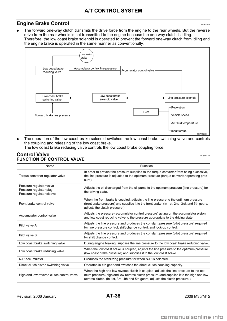
The forward one-way clutch transmits the drive force from the engine to the rear wheels. But the reverse
drive from the rear wheels is not transmitted to the engine because the one-way clutch is idling.
Therefore, the low coast brake solenoid is operated to prevent the forward one-way clutch from idling and
the engine brake is operated in the same manner as conventionally.
The operation of the low coast brake solenoid switches the low coast brake switching valve and controls
the coupling and releasing of the low coast brake.
The low coast brake reducing valve controls the low coast brake coupling force.
Control ValveNCS001JW
FUNCTION OF CONTROL VALVE
SCIA1520E
Name Function
Torque converter regulator valveIn order to prevent the pressure supplied to the torque converter from being excessive,
the line pressure is adjusted to the optimum pressure (torque converter operating pres-
sure).
Pressure regulator valve
Pressure regulator plug
Pressure regulator sleeveAdjusts the oil discharged from the oil pump to the optimum pressure (line pressure) for
the driving state.
Front brake control valveWhen the front brake is coupled, adjusts the line pressure to the optimum pressure
(front brake pressure) and supplies it to the front brake. (In 1st, 2nd, 3rd, and 5th gears,
adjusts the clutch pressure.)
Accumulator control valveAdjusts the pressure (accumulator control pressure) acting on the accumulator piston
and low coast reducing valve to the pressure appropriate to the driving state.
Pilot valve AAdjusts the line pressure and produces the constant pressure (pilot pressure) required
for line pressure control, shift change control, and lock-up control.
Pilot valve BAdjusts the line pressure and produces the constant pressure (pilot pressure) required
for shift change control.
Low coast brake switching valve During engine braking, supplies the line pressure to the low coast brake reducing valve.
Low coast brake reducing valveWhen the low coast brake is coupled, adjusts the line pressure to the optimum pressure
(low coast brake pressure) and supplies it to the low coast brake.
N-R accumulator Produces the stabilizing pressure for when N-R is selected.
Direct clutch piston switching valve Operates in 4th gear and switches the direct clutch coupling capacity.
High and low reverse clutch control valveWhen the high and low reverse clutch is coupled, adjusts the line pressure to the opti-
mum pressure (high and low reverse clutch pressure) and supplies it to the high and low
reverse clutch. (In 1st, 3rd, 4th and 5th gears, adjusts the clutch pressure.)
Page 118 of 5621

A/T CONTROL SYSTEM
AT-39
D
E
F
G
H
I
J
K
L
MA
B
AT
Revision: 2006 January2006 M35/M45
FUNCTION OF PRESSURE SWITCH
Input clutch control valveWhen the input clutch is coupled, adjusts the line pressure to the optimum pressure
(input clutch pressure) and supplies it to the input clutch. (In 4th and 5th gears, adjusts
the clutch pressure.)
Direct clutch control valveWhen the direct clutch is coupled, adjusts the line pressure to the optimum pressure
(direct clutch pressure) and supplies it to the direct clutch. (In 2nd, 3rd, and 4th gears,
adjusts the clutch pressure.)
TCC control valve
TCC control plug
TCC control sleeveSwitches the lock-up to operating or released. Also, by performing the lock-up operation
transiently, lock-up smoothly.
Torque converter lubrication valveOperates during lock-up to switch the torque converter, cooling, and lubrication system
oil passage.
Cool bypass valve Allows excess oil to bypass cooler circuit without being fed into it.
Line pressure relief valve Discharges excess oil from line pressure circuit.
N-D accumulator Produces the stabilizing pressure for when N-D is selected.
Manual valveSends line pressure to each circuit according to the select position. Th e circuits to which
the line pressure is not sent drain. Name Function
Name Function
ATF pressure switch 1 (FR/B)Detects any malfunction in the front brake hydraulic pressure. When it detects any mal-
function, it puts the system into fail-safe mode.
ATF pressure switch 2 (LC/B)Detects any malfunction in the low coast brake hydraulic pressure. When it detects any
malfunction, it puts the system into fail-safe mode.
ATF pressure switch 3 (I/C)Detects any malfunction in the input clutch hydraulic pressure. When it detects any mal-
function, it puts the system into fail-safe mode.
ATF pressure switch 5 (D/C)Detects any malfunction in the direct clutch hydraulic pressure. When it detects any mal-
function, it puts the system into fail-safe mode.
ATF pressure switch 6 (HLR/C)Detects any malfunction in the high and low reverse clutch hydraulic pressure. When it
detects any malfunction, it puts the system into fail-safe mode.
Page 123 of 5621
AT-44
TROUBLE DIAGNOSIS
Revision: 2006 January2006 M35/M45
TROUBLE DIAGNOSISPFP:00004
DTC Inspection Priority ChartNCS001K2
If some DTCs are displayed at the same time, perform inspections one by one based on the following priority
chart.
NOTE:
If DTC “U1000” is displayed with other DTC, first perform the trouble diagnosis for “DTC U1000 CAN
COMMUNICATION LINE”. Refer to AT- 1 0 5
.
Fail-safeNCS001K3
The TCM has an electrical fail-safe mode. This mode makes it possible to operate even if there is an error in a
main electronic control input/output signal circuit.
In fail-safe mode, even if the selector lever is “D” or “M” mode, the A/T is fixed in 2nd, 4th and 5th (depending
on the breakdown position), so the customer should feel “slipping” or “poor acceleration”.
Even when the electronic circuits are normal, under special conditions (for example, when slamming on the
brake with the wheels spinning drastically and stopping the tire rotation), the A/T can go into fail-safe mode. If
this happens, switch OFF the ignition switch for 10 seconds, then switch it ON again to return to the normal
shift pattern. Therefore, the customer's vehicle has returned to normal, so handle according to the “WORK
FLOW” (Refer to AT- 4 7
).
FAIL-SAFE FUNCTION
If any malfunction occurs in a sensor or solenoid, this function controls the A/T to mark driving possible.
Vehicle Speed Sensor
Signals are input from two systems - from vehicle speed sensor A/T (revolution sensor) installed on the A/
T and from combination meter so normal driving is possible even if there is a malfunction in one of the
systems. And if vehicle speed sensor A/T (revolution sensor) has unusual cases, 5th gear and manual
mode are prohibited.
Accelerator Pedal Position Sensor
If there is a malfunction in one of the systems, the accelerator opening angle is controlled by ECM accord-
ing to a pre-determined accelerator angle to make driving possible. And if there are malfunctions in tow
systems, the engine speed is fixed by ECM to a pre-determined engine speed to make driving possible.
Throttle Position Sensor
If there is a malfunction in one of the systems, the accelerator opening angle is controlled by ECM accord-
ing to a pre-determined accelerator angle to make driving possible. And if there are malfunctions in tow
systems, the accelerator opening angle is controlled by the idle signal sent from the ECM which is based
on input indicating either idle condition or off-idle condition (pre-determined accelerator opening) in order
to make driving possible.
PNP Switch
In the unlikely event that a malfunction signal enters the TCM, the position indicator is switched OFF, the
starter relay is switched OFF (starter starting is disabled), the back-up lamp relay switched OFF (back-up
lamp is OFF) and the position is fixed to the “D” position to make driving possible.
Starter Relay
The starter relay is switched OFF. (Starter starting is disabled.)
Priority Detected items (DTC)
1 U1000 CAN communication line
2 Except above
Page 124 of 5621

TROUBLE DIAGNOSIS
AT-45
D
E
F
G
H
I
J
K
L
MA
B
AT
Revision: 2006 January2006 M35/M45
A/T Interlock
If there is an A/T interlock judgment malfunction, the A/T is fixed in 2nd gear to make driving possible.
NOTE:
When the vehicle is driven fixed in 2nd gear, a turbine revolution sensor malfunction is displayed,
but this is not a turbine revolution sensor malfunction.
When the coupling pattern below is detected, the fail-safe action corresponding to the pattern is per-
formed.
A/T INTERLOCK COUPLING PATTERN TABLE
: NG X: OK
A/T 1st Engine Braking
When there is an A/T first gear engine brake judgment malfunction, the low coast brake solenoid is
switched OFF to avoid the engine brake operation.
Line Pressure Solenoid
The solenoid is switched OFF and the line pressure is set to the maximum hydraulic pressure to make
driving possible.
Torque Converter Clutch Solenoid
The solenoid is switched OFF to release the lock-up.
Low Coast Brake Solenoid
When a malfunction (electrical or functional) occurs, in order to make driving possible. If the solenoid is
ON, the A/T is held in 2nd gear. If the solenoid is OFF, the A/T is held in 4th gear. (Engine brake is not
applied in 1st and 2nd gear.)
Input Clutch Solenoid
If a malfunction (electrical or functional) occurs with the solenoid either ON or OFF, the A/T is held in 4th
gear to make driving possible.
Direct Clutch Solenoid
If a malfunction (electrical or functional) occurs with the solenoid either ON or OFF, the A/T is held in 4th
gear to make driving possible.
Front Brake Solenoid
If a malfunction (electrical or functional) occurs with the solenoid ON, in order to make driving possible.
The A/T is held in 5th gear. If the solenoid is OFF, the A/T is 4th gear.
High and Low Reverse Clutch Solenoid
If a (electrical or functional) malfunction occurs with the solenoid either ON or OFF, the A/T is held in 4th
gear to make driving possible.
Turbine Revolution Sensor 1 or 2
The control is the same as if there were no turbine revolution sensors, 5th gear and manual mode are pro-
hibited.
Gear positionATF pressure switch output
Fail-safe
functionClutch pressure output pattern after fail-safe func-
tion
SW3
(I/C)SW6
(HLR/
C)SW5
(D/C)SW1
(FR/B)SW2
(LC/B)I/C HLR/C D/C FR/B LC/B L/U
A/T inter-
lock cou-
pling pattern3rd – X X –
Held in
2nd gearOFF OFF ON OFF OFF OFF
4th – X X –
Held in
2nd gearOFF OFF ON OFF OFF OFF
5th X X – X
Held in
2nd gearOFF OFF ON OFF OFF OFF