coolant INFINITI M35 2006 Factory Service Manual
[x] Cancel search | Manufacturer: INFINITI, Model Year: 2006, Model line: M35, Model: INFINITI M35 2006Pages: 5621, PDF Size: 65.56 MB
Page 4 of 5621

QUICK REFERENCE CHART M35/M45
* : Fuel, engine coolant and engine oil full. Spare tire, jack, hand tools and mats in designated positions.
REAR WHEEL ALIGNMENT (Unladen*)ELS0003Y
* : Fuel, engine coolant and engine oil full. Spare tire, jack, hand tools and mats in designated positions.
BRAKEELS0003Z
* : Under force of 490 N ( 50 kg, 110 lb ) with engine running.
REFILL CAPACITIESELS00040
Wheel turning
angle (Full turn)Inside
Degree minute
(Decimal degree)Minimum 36
20 (36.3)3945 (39.8)
Nominal 39
20 (39.3)4245 (42.8)
Maximum 40
20 (40.3)4345 (43.8)
Outside
Degree minute
(Decimal degree)Nominal 33
25 (33.4)33 20 (33.3)32 30 (32.5) Axle2WD AWD
Tire P245/45R18 245/40R19 245/45R18
Axle2WD AWD
Tire P245/45R18 245/40R19 245/45R18
Camber
Degree minute (Decimal degree)Minimum – 1
10 (– 1.17)– 1 20 (– 1.33)– 1 40 (– 0.67)
Nominal – 0
40 (– 0.67)– 0 50 (– 0.83)– 0 10 (– 0.17)
Maximum – 0
10 (– 0.17)– 0 20 (– 0.33) 0 20 (0.33 )
Total toe-inDistance ( A – B )Minimum 0.1 mm (0.004 in)
Nominal 2.8 mm (0.110 in)
Maximum 5.5 mm (0.217 in)
Angle (left plus right )
Degree minute
(Decimal degree)Minimum 0
(0)
Nominal 7
(0.12)
Maximum 14
(0.23)
Front brake Pad wear limit 2.0 mm (0.079 in)
Rotor repair limit 26.0 mm (1.024 in)
Rear brake Pad wear limit 2.0 mm (0.079 in)
Rotor repair limit 14.0 mm (0.551 in)
Pedal free height 157 - 167 mm (6.18 - 6.57 in)
Pedal depressed height* 90 mm (3.54 in) or more
UNITLiter US measure
Fuel tank76 20 gal
Coolant ( With reservoir tank )VQ35DE 8.9 9 - 3/8 qt
VK45DE 10.4 11 qt
Engine (VQ35DE)Drain and refill
With oil filter change 4.7 5 qt
Without oil filter change 4.4 4 - 5/8 qt
Dry engine (Overhaul) 5.4 5 - 3/4 qt
Engine (VK45DE)Drain and refill
With oil filter change 5.5 5 - 3/4 qt
Without oil filter change 4.9 5 - 1/8 qt
Dry engine (Overhaul) 6.7 7 - 1/8 qt
2006
Page 22 of 5621
![INFINITI M35 2006 Factory Service Manual LASER BEAM AIMING ADJUSTMENT
ACS-13
[ICC]
C
D
E
F
G
H
I
J
L
MA
B
ACS
Revision: 2006 January2006 M35/M45
LASER BEAM AIMING ADJUSTMENTPFP:00026
OutlineNKS004CM
Adjust the laser beam aiming every time th INFINITI M35 2006 Factory Service Manual LASER BEAM AIMING ADJUSTMENT
ACS-13
[ICC]
C
D
E
F
G
H
I
J
L
MA
B
ACS
Revision: 2006 January2006 M35/M45
LASER BEAM AIMING ADJUSTMENTPFP:00026
OutlineNKS004CM
Adjust the laser beam aiming every time th](/img/42/57023/w960_57023-21.png)
LASER BEAM AIMING ADJUSTMENT
ACS-13
[ICC]
C
D
E
F
G
H
I
J
L
MA
B
ACS
Revision: 2006 January2006 M35/M45
LASER BEAM AIMING ADJUSTMENTPFP:00026
OutlineNKS004CM
Adjust the laser beam aiming every time the ICC sensor integrated unit is removed or installed.
CAUTION:
Adjust laser beam aiming at a horizontal place as far as 12 m (39 ft) forward the vehicle can be
seen.
Adjust laser beam aiming 5 seconds after starting engine.
Never view ICC sensor integrated unit body window directly during laser beam aiming adjustment.
Follow the CONSULT-II when adjusting the laser beam aiming (laser beam aiming adjustment can-
not be operated without CONSULT-II).
Never ride on vehicle during laser beam aiming adjustment.
Idle and turn headlamps OFF during laser beam aiming adjustment.
PreparationNKS004CN
Adjust the tire pressure to the specified value.
See that there is no load in the vehicle.
Coolant, engine oil filled up to correct level and full fuel tank.
Shift the gear into “P” position and release the parking brake.
Clean the ICC sensor integrated unit with a soft cloth.
Remove the front bumper grille. Refer to EI-13, "Removal and
Installation of Front Bumper Grille" .
Outline of Adjustment ProcedureNKS004CO
1. Set up the ICC target board [KV99110100 (J-45718)].
2. Adjust the sensor following the procedure on CONSULT-II. (Turn manually the screw for up-down position
adjustment. ICC sensor integrated unit automatically adjust the right-left position.)
Setting the ICC Target BoardNKS004CP
Accurate ICC target board setting is required for the laser beam aiming adjustment.
CAUTION:
ICC system does not function normally if laser beam aiming is not accurate.
ADJUSTING HEIGHT OF THE TARGET
1. Attach a triangle scale at 28 mm (1.10 in) below the center.
PKIB8350E
PKIB8351E
Page 120 of 5621
ON BOARD DIAGNOSTIC (OBD) SYSTEM
AT-41
D
E
F
G
H
I
J
K
L
MA
B
AT
Revision: 2006 January2006 M35/M45
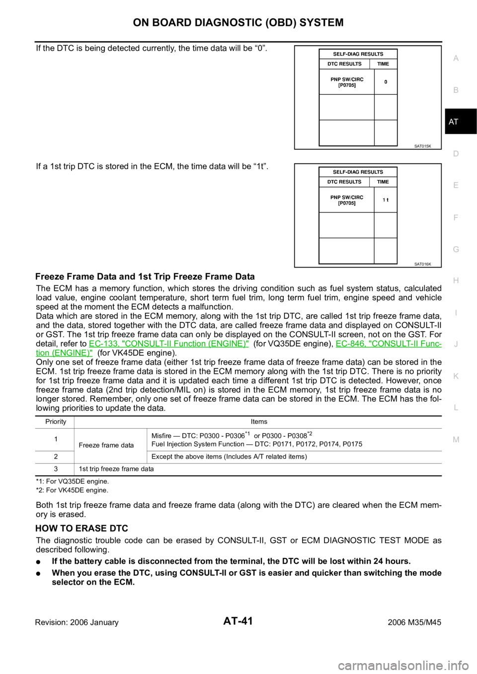
If the DTC is being detected currently, the time data will be “0”.
If a 1st trip DTC is stored in the ECM, the time data will be “1t”.
Freeze Frame Data and 1st Trip Freeze Frame Data
The ECM has a memory function, which stores the driving condition such as fuel system status, calculated
load value, engine coolant temperature, short term fuel trim, long term fuel trim, engine speed and vehicle
speed at the moment the ECM detects a malfunction.
Data which are stored in the ECM memory, along with the 1st trip DTC, are called 1st trip freeze frame data,
and the data, stored together with the DTC data, are called freeze frame data and displayed on CONSULT-II
or GST. The 1st trip freeze frame data can only be displayed on the CONSULT-II screen, not on the GST. For
detail, refer to EC-133, "
CONSULT-II Function (ENGINE)" (for VQ35DE engine), EC-846, "CONSULT-II Func-
tion (ENGINE)" (for VK45DE engine).
Only one set of freeze frame data (either 1st trip freeze frame data of freeze frame data) can be stored in the
ECM. 1st trip freeze frame data is stored in the ECM memory along with the 1st trip DTC. There is no priority
for 1st trip freeze frame data and it is updated each time a different 1st trip DTC is detected. However, once
freeze frame data (2nd trip detection/MIL on) is stored in the ECM memory, 1st trip freeze frame data is no
longer stored. Remember, only one set of freeze frame data can be stored in the ECM. The ECM has the fol-
lowing priorities to update the data.
*1: For VQ35DE engine.
*2: For VK45DE engine.
Both 1st trip freeze frame data and freeze frame data (along with the DTC) are cleared when the ECM mem-
ory is erased.
HOW TO ERASE DTC
The diagnostic trouble code can be erased by CONSULT-II, GST or ECM DIAGNOSTIC TEST MODE as
described following.
If the battery cable is disconnected from the terminal, the DTC will be lost within 24 hours.
When you erase the DTC, using CONSULT-II or GST is easier and quicker than switching the mode
selector on the ECM.
SAT015K
SAT016K
Priority Items
1
Freeze frame dataMisfire — DTC: P0300 - P0306
*1 or P0300 - P0308*2
Fuel Injection System Function — DTC: P0171, P0172, P0174, P0175
2 Except the above items (Includes A/T related items)
3 1st trip freeze frame data
Page 478 of 5621
AIR CONDITIONER CONTROL
ATC-31
C
D
E
F
G
H
I
K
L
MA
B
AT C
Revision: 2006 January2006 M35/M45
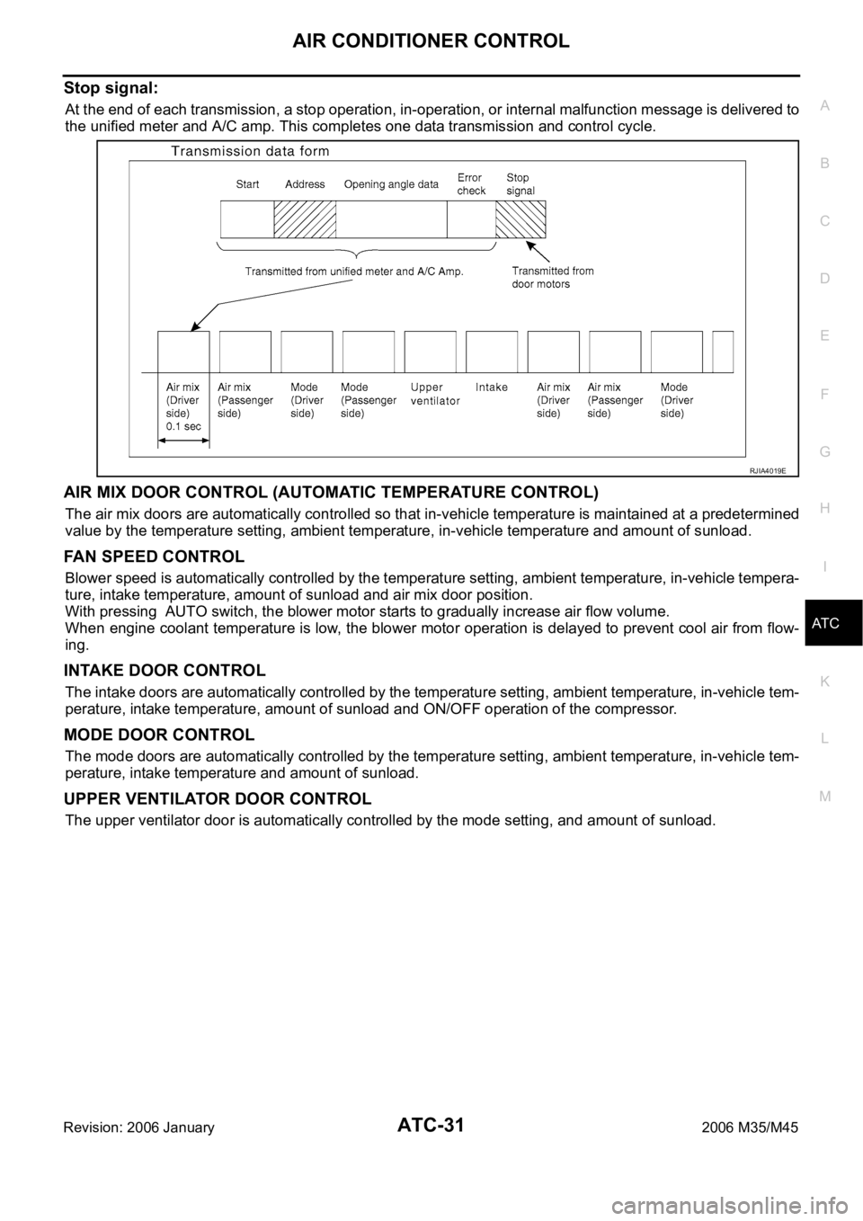
Stop signal:
At the end of each transmission, a stop operation, in-operation, or internal malfunction message is delivered to
the unified meter and A/C amp. This completes one data transmission and control cycle.
AIR MIX DOOR CONTROL (AUTOMATIC TEMPERATURE CONTROL)
The air mix doors are automatically controlled so that in-vehicle temperature is maintained at a predetermined
value by the temperature setting, ambient temperature, in-vehicle temperature and amount of sunload.
FAN SPEED CONTROL
Blower speed is automatically controlled by the temperature setting, ambient temperature, in-vehicle tempera-
ture, intake temperature, amount of sunload and air mix door position.
With pressing AUTO switch, the blower motor starts to gradually increase air flow volume.
When engine coolant temperature is low, the blower motor operation is delayed to prevent cool air from flow-
ing.
INTAKE DOOR CONTROL
The intake doors are automatically controlled by the temperature setting, ambient temperature, in-vehicle tem-
perature, intake temperature, amount of sunload and ON/OFF operation of the compressor.
MODE DOOR CONTROL
The mode doors are automatically controlled by the temperature setting, ambient temperature, in-vehicle tem-
perature, intake temperature and amount of sunload.
UPPER VENTILATOR DOOR CONTROL
The upper ventilator door is automatically controlled by the mode setting, and amount of sunload.
RJIA4019E
Page 538 of 5621
TROUBLE DIAGNOSIS
ATC-91
C
D
E
F
G
H
I
K
L
MA
B
AT C
Revision: 2006 January2006 M35/M45
Starting Fan Speed Control
Start up from COLD SOAK Condition (Automatic mode)
In a cold start up condition where the engine coolant temperature is below 56
C (133F), the blower will not
operate for a short period of time (up to 150 seconds). The exact start delay time varies depending on the
ambient and engine coolant temperature.
In the most extreme case (very low ambient) the blower starting delay will be 150 seconds as described
above. After this delay, the blower will operate at low speed until the engine coolant temperature rises above
56
C (133F), at which time the blower speed will increase to the objective speed.
Start up from usual or HOT SOAK Condition (Automatic mode)
The blower will begin operation momentarily after the AUTO switch is pressed. The blower speed will gradu-
ally rise to the objective speed over a time period of 3 seconds or less (actual time depends on the objective
blower speed).
Blower Speed Compensation
Sunload
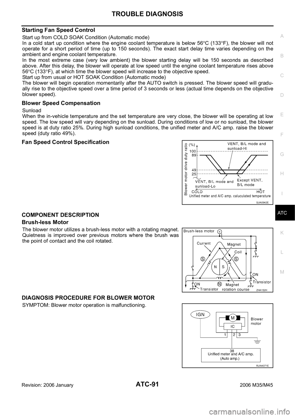
When the in-vehicle temperature and the set temperature are very close, the blower will be operating at low
speed. The low speed will vary depending on the sunload. During conditions of low or no sunload, the blower
speed is at duty ratio 25%. During high sunload conditions, the unified meter and A/C amp. raise the blower
speed (duty ratio 49%).
Fan Speed Control Specification
COMPONENT DESCRIPTION
Brush-less Motor
The blower motor utilizes a brush-less motor with a rotating magnet.
Quietness is improved over previous motors where the brush was
the point of contact and the coil rotated.
DIAGNOSIS PROCEDURE FOR BLOWER MOTOR
SYMPTOM: Blower motor operation is malfunctioning.
SJIA0942E
ZHA152H
RJIA4071E
Page 556 of 5621
TROUBLE DIAGNOSIS
ATC-109
C
D
E
F
G
H
I
K
L
MA
B
AT C
Revision: 2006 January2006 M35/M45
Insufficient HeatingNJS000GW
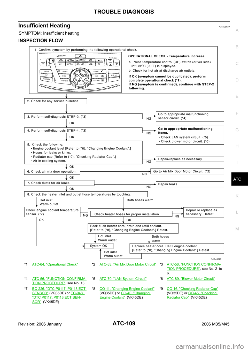
SYMPTOM: Insufficient heating
INSPECTION FLOW
*1ATC-64, "Operational Check"*2ATC-83, "Air Mix Door Motor Circuit"*3AT C - 5 6 , "FUNCTION CONFIRMA-
TION PROCEDURE", see No. 2 to
6.
*4ATC-56, "
FUNCTION CONFIRMA-
TION PROCEDURE", see No. 13.*5ATC-70, "
LAN System Circuit"*6AT C - 8 9 , "Blower Motor Circuit"
*7EC-226, "DTC P0117, P0118 ECT
SENSOR" (VQ35DE) or EC-948,
"DTC P0117, P0118 ECT SEN-
SOR" (VK45DE)*8CO-11, "
Changing Engine Coolant"
(VQ35DE) or CO-40, "
Changing
Engine Coolant" (VK45DE)*9CO-16, "
Checking Radiator Cap"
(VQ35DE) or CO-45, "
Checking
Radiator Cap" (VK45DE)
RJIA4084E
Page 582 of 5621
HEATER & COOLING UNIT ASSEMBLY
ATC-135
C
D
E
F
G
H
I
K
L
MA
B
AT C
Revision: 2006 January2006 M35/M45
HEATER & COOLING UNIT ASSEMBLYPFP:27110
Removal and InstallationNJS000HF
REMOVAL
1. Use a refrigerant collecting equipment (for HFC-134a) to discharge the refrigerant.
2. Drain coolant from cooling system. Refer to CO-11, "
Changing Engine Coolant" (VQ35DE) or CO-40,
"Changing Engine Coolant" (VK45DE).
3. Remove cowl top cover. Refer to EI-18, "
COWL TOP" .
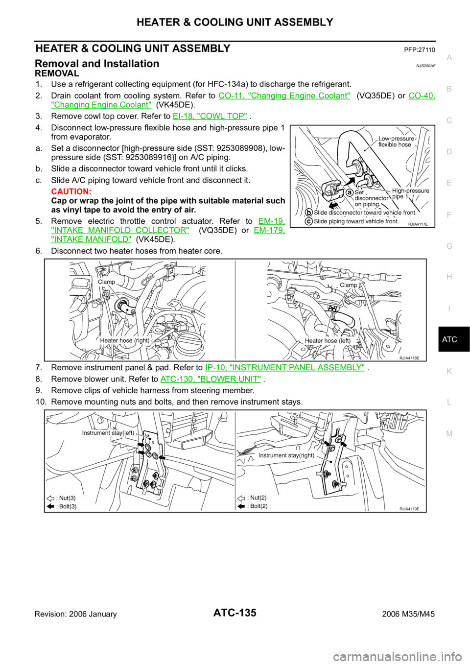
4. Disconnect low-pressure flexible hose and high-pressure pipe 1
from evaporator.
a. Set a disconnector [high-pressure side (SST: 9253089908), low-
pressure side (SST: 9253089916)] on A/C piping.
b. Slide a disconnector toward vehicle front until it clicks.
c. Slide A/C piping toward vehicle front and disconnect it.
CAUTION:
Cap or wrap the joint of the pipe with suitable material such
as vinyl tape to avoid the entry of air.
5. Remove electric throttle control actuator. Refer to EM-19,
"INTAKE MANIFOLD COLLECTOR" (VQ35DE) or EM-179,
"INTAKE MANIFOLD" (VK45DE).
6. Disconnect two heater hoses from heater core.
7. Remove instrument panel & pad. Refer to IP-10, "
INSTRUMENT PANEL ASSEMBLY" .
8. Remove blower unit. Refer to ATC-130, "
BLOWER UNIT" .
9. Remove clips of vehicle harness from steering member.
10. Remove mounting nuts and bolts, and then remove instrument stays.
RJIA4117E
RJIA4118E
RJIA4119E
Page 584 of 5621
HEATER & COOLING UNIT ASSEMBLY
ATC-137
C
D
E
F
G
H
I
K
L
MA
B
AT C
Revision: 2006 January2006 M35/M45
CAUTION:
Replace O-rings of A/C piping with new ones, and then apply compressor oil to it when installing
it.
Female-side piping connection is thin and easy to deform. Slowly insert the male-side piping
straight in axial direction.
Insert piping securely until a click is heard.
After piping connection is completed, pull male-side piping by hand to make sure that connection
does not come loose.
When recharging refrigerant, check for leaks.
NOTE:
When filling radiator with coolant, refer to CO-11, "Changing Engine Coolant" (VQ35DE) or CO-40,
"Changing Engine Coolant" (VK45DE).
Recharge the refrigerant.
Heater & cooling unit assembly mounting bolt
: 6.9 Nꞏm (0.7 kg-m, 61 in-lb)
Instrument stay mounting nut and bolt
: 12 Nꞏm (1.25 kg-m, 9 ft-lb)
Page 612 of 5621
REFRIGERANT LINES
ATC-165
C
D
E
F
G
H
I
K
L
MA
B
AT C
Revision: 2006 January2006 M35/M45
INSTALLATION
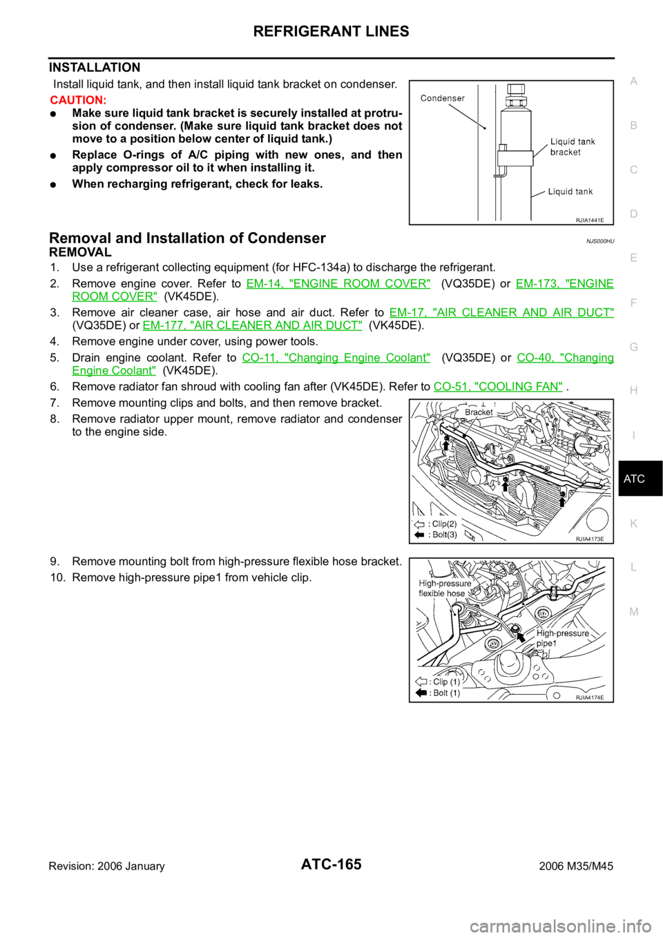
Install liquid tank, and then install liquid tank bracket on condenser.
CAUTION:
Make sure liquid tank bracket is securely installed at protru-
sion of condenser. (Make sure liquid tank bracket does not
move to a position below center of liquid tank.)
Replace O-rings of A/C piping with new ones, and then
apply compressor oil to it when installing it.
When recharging refrigerant, check for leaks.
Removal and Installation of CondenserNJS000HU
REMOVAL
1. Use a refrigerant collecting equipment (for HFC-134a) to discharge the refrigerant.
2. Remove engine cover. Refer to EM-14, "
ENGINE ROOM COVER" (VQ35DE) or EM-173, "ENGINE
ROOM COVER" (VK45DE).
3. Remove air cleaner case, air hose and air duct. Refer to EM-17, "
AIR CLEANER AND AIR DUCT"
(VQ35DE) or EM-177, "AIR CLEANER AND AIR DUCT" (VK45DE).
4. Remove engine under cover, using power tools.
5. Drain engine coolant. Refer to CO-11, "
Changing Engine Coolant" (VQ35DE) or CO-40, "Changing
Engine Coolant" (VK45DE).
6. Remove radiator fan shroud with cooling fan after (VK45DE). Refer to CO-51, "
COOLING FAN" .
7. Remove mounting clips and bolts, and then remove bracket.
8. Remove radiator upper mount, remove radiator and condenser
to the engine side.
9. Remove mounting bolt from high-pressure flexible hose bracket.
10. Remove high-pressure pipe1 from vehicle clip.
RJIA1441E
RJIA4173E
RJIA4174E
Page 1376 of 5621
CO-1
ENGINE COOLING SYSTEM
B ENGINE
CONTENTS
C
D
E
F
G
H
I
J
K
L
M
SECTION CO
A
CO
Revision: 2006 January2006 M35/M45
ENGINE COOLING SYSTEM
VQ35DE
PRECAUTIONS .......................................................... 3
Precautions for Supplemental Restraint System
(SRS) “AIR BAG” and “SEAT BELT PRE-TEN-
SIONER” .................................................................. 3
Precautions for Liquid Gasket .................................. 3
REMOVAL OF LIQUID GASKET SEALING .......... 3
LIQUID GASKET APPLICATION PROCEDURE ..... 3
PREPARATION ........................................................... 5
Special Service Tools ............................................... 5
Commercial Service Tools ........................................ 6
OVERHEATING CAUSE ANALYSIS .......................... 7
Troubleshooting Chart .............................................. 7
COOLING SYSTEM .................................................... 9
Cooling Circuit .......................................................... 9
System Chart ......................................................... 10
ENGINE COOLANT ...................................................11
Inspection ................................................................ 11
LEVEL CHECK .................................................... 11
LEAK CHECK ...................................................... 11
Changing Engine Coolant ....................................... 11
DRAINING ENGINE COOLANT .......................... 11
REFILLING ENGINE COOLANT ........................ 12
FLUSHING COOLING SYSTEM ......................... 13
RADIATOR ................................................................ 14
Components ........................................................... 14
Removal and Installation ........................................ 14
REMOVAL ........................................................
... 14
INSTALLATION ................................................... 16
INSPECTION AFTER INSTALLATION ............... 16
Checking Radiator Cap .......................................... 16
Checking Radiator .................................................. 16
RADIATOR (ALUMINUM TYPE) .............................. 18
Components ........................................................... 18
Disassembly and Assembly ................................... 18
PREPARATION ................................................... 18
DISASSEMBLY ................................................... 18
ASSEMBLY ......................................................... 19
INSPECTION ...................................................... 21COOLING FAN .......................................................... 22
Components ........................................................... 22
Removal and Installation ........................................ 22
REMOVAL ........................................................
... 22
INSTALLATION ................................................... 22
INSPECTION AFTER INSTALLATION ................ 22
Disassembly and Assembly .................................... 23
DISASSEMBLY ................................................... 23
INSPECTION AFTER DISASSEMBLY ................ 23
ASSEMBLY ......................................................... 23
WATER PUMP .......................................................... 24
Components ........................................................... 24
Removal and Installation ........................................ 24
REMOVAL ........................................................
... 24
INSPECTION AFTER REMOVAL ....................... 26
INSTALLATION ................................................... 26
INSPECTION AFTER INSTALLATION ................ 28
WATER INLET AND THERMOSTAT ASSEMBLY .... 29
Components ........................................................... 29
Removal and Installation ........................................ 29
REMOVAL ........................................................
... 29
INSPECTION AFTER REMOVAL ....................... 30
INSTALLATION ................................................... 30
INSPECTION AFTER INSTALLATION ................ 30
WATER OUTLET AND WATER PIPING ................... 31
Components ........................................................... 31
Removal and Installation ........................................ 31
REMOVAL ........................................................
... 31
INSTALLATION ................................................... 32
INSPECTION AFTER INSTALLATION ................ 32
SERVICE DATA AND SPECIFICATIONS (SDS) ...... 33
Standard and Limit .................................................. 33
ENGINE COOLANT CAPACITY (APPROXI-
MATE) .................................................................. 33
RADIATOR .......................................................
... 33
THERMOSTAT .................................................... 33