display INFINITI M35 2006 Factory Service Manual
[x] Cancel search | Manufacturer: INFINITI, Model Year: 2006, Model line: M35, Model: INFINITI M35 2006Pages: 5621, PDF Size: 65.56 MB
Page 3058 of 5621
HEADLINING
EI-53
C
D
E
F
G
H
J
K
L
MA
B
EI
Revision: 2006 January2006 M35/M45
REMOVAL
1. Remove front pillar garnish (LH/RH). Refer to EI-37, "BODY SIDE TRIM" .
2. Remove roof harness and antenna feeder securing clip using a clip clamp remover after removing front
pillar garnish (LH/RH), and then disconnect roof harness and antenna feeder connectors.
3. Remove rear seat cushion and seatback. Refer to SE-172, "
REAR SEAT" .
4. Remove front kicking plate inner, center pillar lower garnish, center pillar upper garnish, front body side
welt, rear kicking plate inner, rear wheelhouse garnish, rear pillar finisher, rear body side welt. Refer to EI-
37, "BODY SIDE TRIM" .
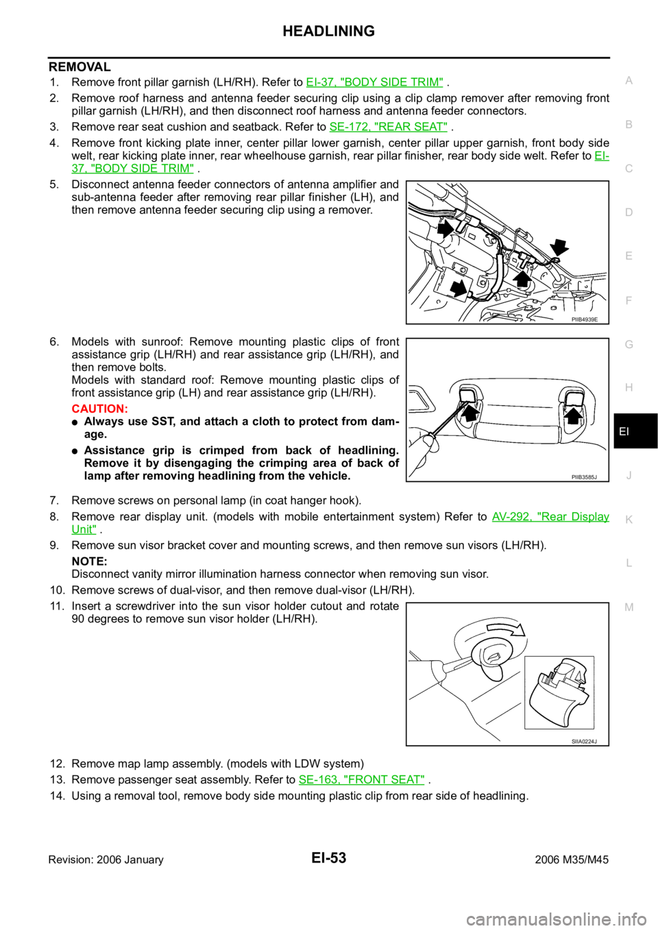
5. Disconnect antenna feeder connectors of antenna amplifier and
sub-antenna feeder after removing rear pillar finisher (LH), and
then remove antenna feeder securing clip using a remover.
6. Models with sunroof: Remove mounting plastic clips of front
assistance grip (LH/RH) and rear assistance grip (LH/RH), and
then remove bolts.
Models with standard roof: Remove mounting plastic clips of
front assistance grip (LH) and rear assistance grip (LH/RH).
CAUTION:
Always use SST, and attach a cloth to protect from dam-
age.
Assistance grip is crimped from back of headlining.
Remove it by disengaging the crimping area of back of
lamp after removing headlining from the vehicle.
7. Remove screws on personal lamp (in coat hanger hook).
8. Remove rear display unit. (models with mobile entertainment system) Refer to AV- 2 9 2 , "
Rear Display
Unit" .
9. Remove sun visor bracket cover and mounting screws, and then remove sun visors (LH/RH).
NOTE:
Disconnect vanity mirror illumination harness connector when removing sun visor.
10. Remove screws of dual-visor, and then remove dual-visor (LH/RH).
11. Insert a screwdriver into the sun visor holder cutout and rotate
90 degrees to remove sun visor holder (LH/RH).
12. Remove map lamp assembly. (models with LDW system)
13. Remove passenger seat assembly. Refer to SE-163, "
FRONT SEAT" .
14. Using a removal tool, remove body side mounting plastic clip from rear side of headlining.
PIIB4939E
PIIB3585J
SIIA0224J
Page 3434 of 5621
![INFINITI M35 2006 Factory Service Manual FRONT SUSPENSION ASSEMBLY
FSU-7
[2WD]
C
D
F
G
H
I
J
K
L
MA
B
FSU
Revision: 2006 January2006 M35/M45
THE ALIGNMENT PROCESS
IMPORTANT:
Use only the alignment specifications listed in this Service Manual INFINITI M35 2006 Factory Service Manual FRONT SUSPENSION ASSEMBLY
FSU-7
[2WD]
C
D
F
G
H
I
J
K
L
MA
B
FSU
Revision: 2006 January2006 M35/M45
THE ALIGNMENT PROCESS
IMPORTANT:
Use only the alignment specifications listed in this Service Manual](/img/42/57023/w960_57023-3433.png)
FRONT SUSPENSION ASSEMBLY
FSU-7
[2WD]
C
D
F
G
H
I
J
K
L
MA
B
FSU
Revision: 2006 January2006 M35/M45
THE ALIGNMENT PROCESS
IMPORTANT:
Use only the alignment specifications listed in this Service Manual.
When displaying the alignment settings, many alignment machines use “indicators”: (Green/red, plus or
minus, Go/No Go). Do NOT use these indicators.
–The alignment specifications programmed into your machine that operate these indicators may not be cor-
rect.
–This may result in an ERROR.
Some newer alignment machines are equipped with an optional “Rolling Compensation” method to “com-
pensate” the sensors (alignment targets or head units). DO NOT use this “Rolling Compensation”
method.
–Use the “Jacking Compensation Method”. After installing the alignment targets or head units, raise the
vehicle and rotate the wheels 1/2 turn both ways.
–See Instructions in the alignment machine you're using for more information on this.
INSPECTION OF CAMBER, CASTER AND KINGPIN INCLINATION ANGLES
Camber, caster, kingpin inclination angles cannot be adjusted.
Before inspection, mount front wheels onto turning radius gauge. Mount rear wheels onto a stand that has
same height so vehicle will remain horizontal.
Using a CCK Gauge
Install the CCK gauge attachment [SST: KV991040S0 ( – )] with the following procedure on wheel, then
measure wheel alignment.
1. Remove three wheel nuts, and install the guide bolts to hub bolt.
2. Screw the adapter into the plate until it contacts the plate tightly.
3. Screw the center plate into the plate.
4. Insert the plate assembly on the guide bolt. Put the spring in,
and then evenly screw the three guide bolt nuts. When fastening
the guide nuts, do not completely compress the spring.
5. Place the dent of alignment gauge onto the projection of the
center plate and tightly contact them to measure.
CAUTION:
If camber, caster, or kingpin inclination angle is outside
the standard, check front suspension parts for wear and
damage. Replace suspect parts if a malfunction is
detected.
Kingpin inclination angle is reference value, no inspec-
tion is required.
SEIA0240E
Camber, caster, kingpin inclination angles:
Refer to FSU-19, "
SERVICE DATA AND SPECIFICA-
TIONS (SDS)" .
SEIA0241E
Page 3451 of 5621
![INFINITI M35 2006 Factory Service Manual FSU-24
[AWD]
FRONT SUSPENSION ASSEMBLY
Revision: 2006 January2006 M35/M45
THE ALIGNMENT PROCESS
IMPORTANT:
Use only the alignment specifications listed in this Service Manual.
When displaying the a INFINITI M35 2006 Factory Service Manual FSU-24
[AWD]
FRONT SUSPENSION ASSEMBLY
Revision: 2006 January2006 M35/M45
THE ALIGNMENT PROCESS
IMPORTANT:
Use only the alignment specifications listed in this Service Manual.
When displaying the a](/img/42/57023/w960_57023-3450.png)
FSU-24
[AWD]
FRONT SUSPENSION ASSEMBLY
Revision: 2006 January2006 M35/M45
THE ALIGNMENT PROCESS
IMPORTANT:
Use only the alignment specifications listed in this Service Manual.
When displaying the alignment settings, many alignment machines use “indicators”: (Green/red, plus or
minus, Go/No Go). Do NOT use these indicators.
–The alignment specifications programmed into your machine that operate these indicators may not be cor-
rect.
–This may result in an ERROR.
Some newer alignment machines are equipped with an optional “Rolling Compensation” method to “com-
pensate” the sensors (alignment targets or head units). DO NOT use this “Rolling Compensation”
method.
–Use the “Jacking Compensation Method”. After installing the alignment targets or head units, raise the
vehicle and rotate the wheels 1/2 turn both ways.
–See Instructions in the alignment machine you're using for more information on this.
INSPECTION OF CAMBER, CASTER AND KINGPIN INCLINATION ANGLES
Camber, caster, kingpin inclination angles cannot be adjusted.
Before inspection, mount front wheels onto turning radius gauge. Mount rear wheels onto a stand that has
same height so vehicle will remain horizontal.
Using a CCK Gauge
Install the CCK gauge attachment [SST: KV991040S0 ( – )] with the following procedure on wheel, then
measure wheel alignment.
1. Remove three wheel nuts, and install the guide bolts to hub bolt.
2. Screw the adapter into the plate until it contacts the plate tightly.
3. Screw the center plate into the plate.
4. Insert the plate assembly on the guide bolt. Put the spring in,
and then evenly screw the three guide bolt nuts. When fastening
the guide nuts, do not completely compress the spring.
5. Place the dent of alignment gauge onto the projection of the
center plate and tightly contact them to measure.
CAUTION:
If camber, caster, or kingpin inclination angle is outside
the standard, check front suspension parts for wear and
damage. Replace suspect parts if a malfunction is
detected.
Kingpin inclination angle is reference value, no inspec-
tion is required.
SEIA0240E
Camber, caster, kingpin inclination angles:
Refer to FSU-36, "
SERVICE DATA AND SPECIFICA-
TIONS (SDS)" .
SEIA0241E
Page 3549 of 5621
GW-30
POWER WINDOW SYSTEM
Revision: 2006 January2006 M35/M45
CONSULT-II Function (BCM)NIS0021O
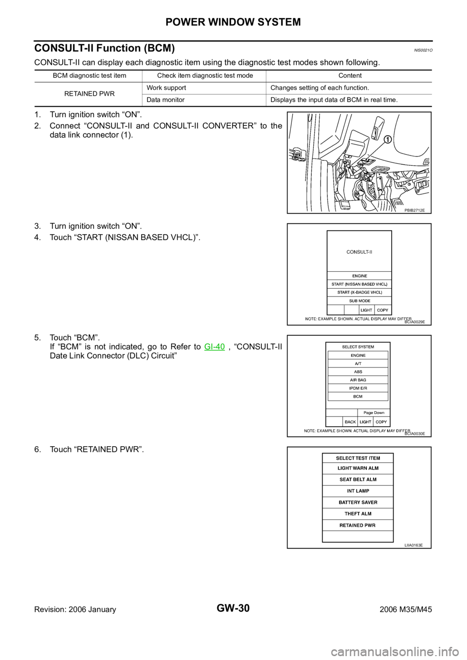
CONSULT-II can display each diagnostic item using the diagnostic test modes shown following.
1. Turn ignition switch “ON”.
2. Connect “CONSULT-II and CONSULT-II CONVERTER” to the
data link connector (1).
3. Turn ignition switch “ON”.
4. Touch “START (NISSAN BASED VHCL)”.
5. Touch “BCM”.
If “BCM” is not indicated, go to Refer to GI-40
, “CONSULT-II
Date Link Connector (DLC) Circuit”
6. Touch “RETAINED PWR”.
BCM diagnostic test item Check item diagnostic test mode Content
RETAINED PWRWork support Changes setting of each function.
Data monitor Displays the input data of BCM in real time.
PBIB2712E
BCIA0029E
BCIA0030E
LIIA0163E
Page 3593 of 5621

GW-74
REAR WINDOW DEFOGGER
Revision: 2006 January2006 M35/M45
through 50A fusible link (letter F , located in the fuse and fusible link box)
to BCM terminal 55,
through 10A fuse [No. 21, located in the fuse block (J/B)]
to BCM terminal 42.
With the ignition switch turned to ON or START position,
Power is supplied
through 15A fuse [No. 1, located in the fuse block (J/B)]
to BCM terminal 38.
through 10A fuse [No. 12, located in the fuse block (J/B)]
to rear window defogger relay terminal 1.
With the ignition switch turned to ACC or ON position,
through 10A fuse [No. 6, located in the fuse block (J/B)]
to multi-function switch terminal 2.
Ground is supplied
to BCM terminal 52
through body grounds M16 and M70,
to multi-function switch terminal 14
through body grounds M16 and M70,
to IPDM E/R terminals 38 and 51
through body grounds E22 and E43.
When rear window defogger switch in multi-function switch is turned to ON.
Then multi-function switch recognizes that rear window defogger switch is turned to ON.
Then it sends rear window defogger switch signals to AV control unit (without navigation system) or NAVI con-
trol unit (with navigation system) via AV line.
When AV control unit (without navigation system) or NAVI control unit (with navigation system) receives rear
window defogger switch signals, and display on the screen.
Then AV control unit (without navigation system) or NAVI control unit (with navigation system) recognizes that
rear window defogger switch is turned to ON.
Then it sends rear window defogger switch signal to BCM via DATA LINE (CAN H, CAN L).
Then BCM recognizes that rear window defogger switch signal.
Then it sends rear window defogger request signal to IPDM E/R via DATA LINE (CAN H, CAN L).
When IPDM E/R receives rear window defogger switch signals,
Ground is supplied
to rear window defogger relay terminal 2
through IPDM E/R terminal 57
through IPDM E/R terminal 51
through body grounds E22 and E43.
And then rear window defogger relay is energized.
When rear window defogger relay is turned ON, signals are transmitted.
through rear window defogger relay terminals 5 and 7
through condenser terminal 1
to rear window defogger terminal 1
Rear window defogger terminal 2 is grounded through grounds B702.
With power and ground supplied, rear window defogger filaments heat and defog the rear window.
When rear window defogger relay is turned to ON,
Power is supplied
through rear window defogger relay terminals 5 and 7
through fuse block (J/B) terminal 2C
through 10A fuse [No. 8, located in the fuse block (J/B)] and
through fuse block (J/B) terminal 5B
to door mirror (LH and RH) terminal 4.
Door mirror (LH and RH) terminal 8 is grounded through body grounds M16 and M70.
Page 3602 of 5621
REAR WINDOW DEFOGGER
GW-83
C
D
E
F
G
H
J
K
L
MA
B
GW
Revision: 2006 January2006 M35/M45
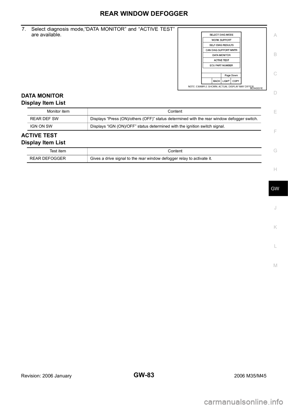
7. Select diagnosis mode,“DATA MONITOR” and “ACTIVE TEST”
are available.
DATA MONITOR
Display Item List
ACTIVE TEST
Display Item List
BCIA0031E
Monitor item Content
REAR DEF SW Displays “Press (ON)/others (OFF)” status determined with the rear window defogger switch.
IGN ON SW Displays “IGN (ON)/OFF” status determined with the ignition switch signal.
Test item Content
REAR DEFOGGER Gives a drive signal to the rear window defogger relay to activate it.
Page 3603 of 5621
GW-84
REAR WINDOW DEFOGGER
Revision: 2006 January2006 M35/M45
Work FlowNIS0022P
1. Check the symptom and customer's requests.
2. Understand the outline of system. Refer to GW-73, "
System Description" .
3. According to the trouble diagnosis chart, repair or replace the cause of the malfunction. Refer to GW-84,
"Trouble Diagnoses Symptom Chart" .
4. Does rear window defogger operate normally? YES: GO TO 5, NO: GO TO 3.
5. INSPECTION END.
Trouble Diagnoses Symptom ChartNIS0022Q
Make sure other systems using the signal of the following systems operate normally.
*1: With navigation system
*2: Without navigation systemSymptom Diagnoses / Service procedure Refer to page
Rear window defogger and door mirror defogger do not
operate. 1. BCM power supply and ground circuit check.GW-85
2. IPDM E/R auto active test checkPG-24
3. Rear window defogger switch circuit checkGW-86
4. Rear window defogger power supply circuit checkGW-86
5. Replace IPDM E/ RPG-31
Rear window defogger does not operate but both of door
mirror defogger operate.1. Rear window defogger circuit checkGW-88
2. Filament checkGW-94
Both of door mirror defogger does not operated but rear
window defogger operates. 1. Door mirror defogger power supply circuit checkGW-89
Driver side door mirror defogger does not operate. 1. Driver side door mirror defogger circuit checkGW-91
Passenger side door mirror defogger does not operate. 1. Passenger side door mirror defogger circuit checkGW-92
Rear window defogger switch does not light, and rear win-
dow defogger is not displayed on the display.
But rear window defogger operates. 1. Rear window defogger signal checkAV-253*1
AV-108*2
Rear window defogger switch does not light, but rear win-
dow defogger operates1. Replace multi-function switchATC-124
Page 3625 of 5621
GW-106
REVERSE INTERLOCK DOOR MIRROR SYSTEM
Revision: 2006 January2006 M35/M45
CONSULT-II Function (AUTO DRIVE POS.)NIS00238
CONSULT-II can display each diagnostic item using the diagnostic test modes shown following.
*1: For setting automatic drive positioner functions only.
*2: During vehicle driving, do not perform active test.
CONSULT-II INSPECTION PROCEDURE
CAUTION:
If CONSULT-II is used with no connection of CONSULT-II CONVERTER, malfunctions might be
detected in self-diagnosis depending on control unit which carry out CAN communication.
1. Turn ignition switch “OFF”.
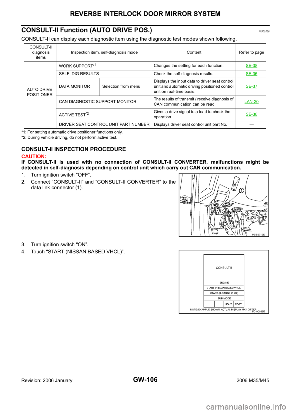
2. Connect “CONSULT-II” and “CONSULT-II CONVERTER” to the
data link connector (1).
3. Turn ignition switch “ON”.
4. Touch “START (NISSAN BASED VHCL)”.
CONSULT-II
diagnosis
itemsInspection item, self-diagnosis mode Content Refer to page
AUTO DRIVE
POSITIONERWORK SUPPORT*
1Changes the setting for each function.SE-38
SELF–DIG RESULTS Check the self-diagnosis results.SE-36
DATA MONITOR Selection from menuDisplays the input data to driver seat control
unit and automatic driving positioned control
unit on real-time basis.SE-37
CAN DIAGNOSTIC SUPPORT MONITORThe results of transmit / receive diagnosis of
CAN communication can be readLAN-20
ACTIVE TEST*2Gives a drive signal to a load to check the
operation.SE-38
DRIVER SEAT CONTROL UNIT PART NUMBER Displays driver seat control unit part No. —
PBIB2712E
BCIA0029E
Page 3626 of 5621
REVERSE INTERLOCK DOOR MIRROR SYSTEM
GW-107
C
D
E
F
G
H
J
K
L
MA
B
GW
Revision: 2006 January2006 M35/M45
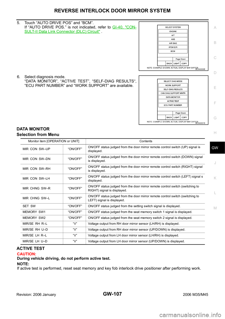
5. Touch “AUTO DRIVE POS” and “BCM”.
If “AUTO DRIVE POS.” is not indicated, refer to GI-40, "
CON-
SULT-II Data Link Connector (DLC) Circuit" .
6. Select diagnosis mode.
“DATA MONITOR”, “ACTIVE TEST”, “SELF-DIAG RESULTS“,
“ECU PART NUMBER” and “WORK SUPPORT” are available.
DATA MONITOR
Selection from Menu
ACTIVE TEST
CAUTION:
During vehicle driving, do not perform active test.
NOTE:
If active test is performed, reset seat memory and key fob interlock drive positioner after performing work.
BCIA0030E
BCIA0031E
Monitor item [OPERATION or UNIT] Contents
MIR CON SW–UP “ON/OFF”ON/OFF status judged from the door mirror remote control switch (UP) signal is
displayed.
MIR CON SW–DN “ON/OFF”ON/OFF status judged from the door mirror remote control switch (DOWN) signal
is displayed.
MIR CON SW–RH “ON/OFF”ON/OFF status judged from the door mirror remote control switch (RIGHT) signal
is displayed.
MIR CON SW–LH “ON/OFF”ON/OFF status judged from the door mirror remote control switch (LEFT) signal s
displayed.
MIR CHNG SW–R “ON/OFF”ON/OFF status judged from the door mirror remote control switch (switching to
RIGHT) signal is displayed.
MIR CHNG SW–L “ON/OFF”ON/OFF status judged from the door mirror remote control switch (switching to
LEFT) signal is displayed.
SET SW “ON/OFF” ON/OFF status judged from the setting switch signal is displayed.
MEMORY SW1 “ON/OFF” ON/OFF status judged from the seat memory switch 1 signal is displayed.
MEMORY SW2 “ON/OFF” ON/OFF status judged from the seat memory switch 2 signal is displayed.
MIR/SE RH R–L “V” Voltage output from RH door mirror sensor (LH/RH) is displayed.
MIR/SE RH U–D “V” Voltage output from RH door mirror sensor (UP/DOWN) is displayed.
MIR/SE LH R–L “V” Voltage output from LH door mirror sensor (LH/RH) is displayed.
MIR/SE LH U–D “V” Voltage output from LH door mirror sensor (UP/DOWN) is displayed.
Page 3627 of 5621
GW-108
REVERSE INTERLOCK DOOR MIRROR SYSTEM
Revision: 2006 January2006 M35/M45
Display Item List
Work Flow NIS00239
1. Check the symptom and customer's requests.
2. Understand the system description. Refer to GW-96, "
System Description" .
3. According to the trouble diagnosis chart, repair or replace the cause of the malfunction. Refer to GW-109,
"Check Changeover Switch Circuit" .
4. Does reverse interlock door mirror system operate normally?
Yes , GO TO 5.
No, GO TO 3.
5. INSPECTION END
Symptom ChartNIS0023A
Test item Description
MIRROR MOTOR RHThe RH mirror motor moves the mirror UP/DOWN and LEFT/RIGHT by receiving the drive
signal.
MIRROR MOTOR LHThe LH mirror motor moves the mirror UP/DOWN and LEFT/RIGHT by receiving the drive
signal.
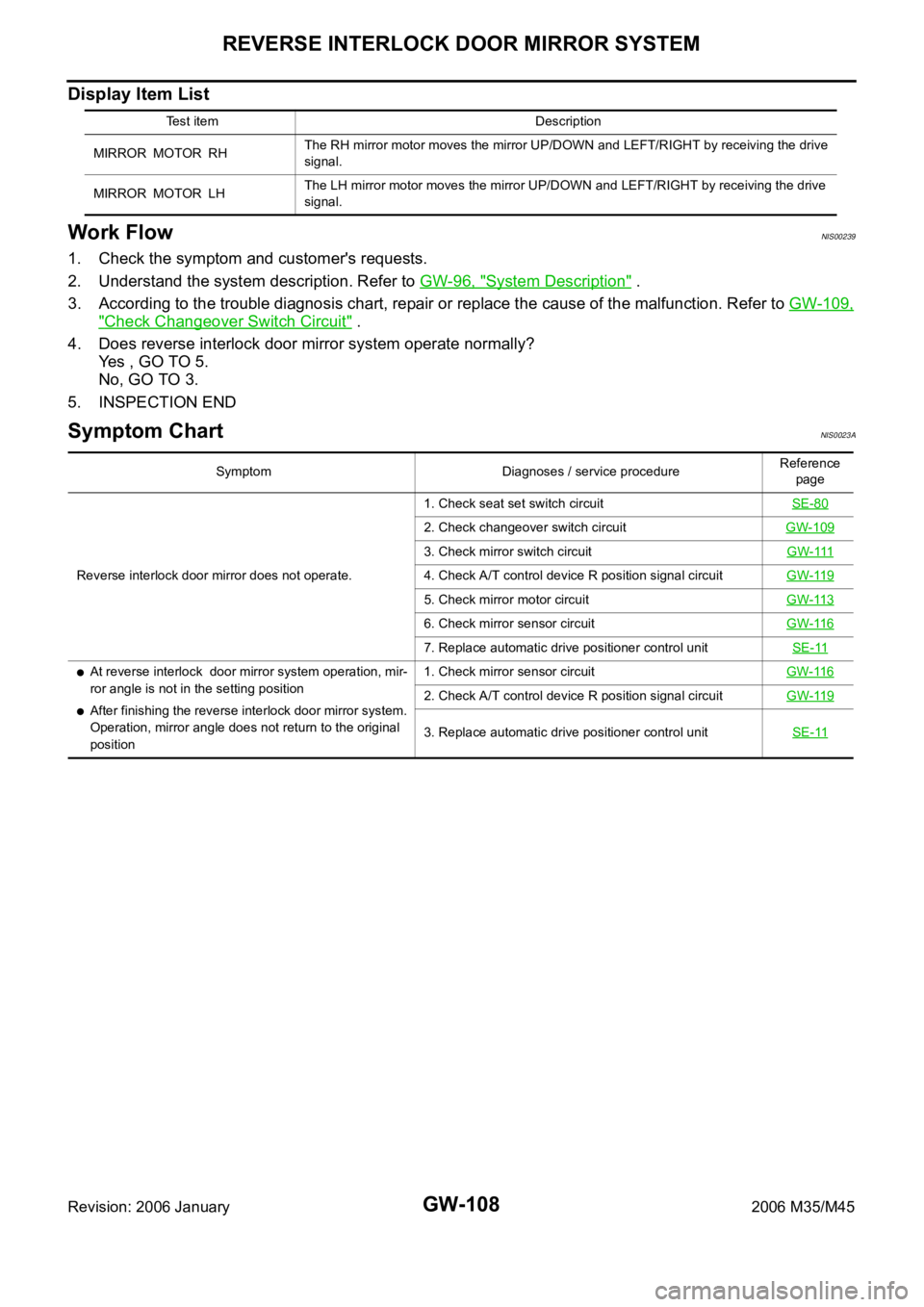
Symptom Diagnoses / service procedureReference
page
Reverse interlock door mirror does not operate.1. Check seat set switch circuitSE-80
2. Check changeover switch circuitGW-109
3. Check mirror switch circuitGW-111
4. Check A/T control device R position signal circuitGW-119
5. Check mirror motor circuitGW-113
6. Check mirror sensor circuitGW-116
7. Replace automatic drive positioner control unitSE-11
At reverse interlock door mirror system operation, mir-
ror angle is not in the setting position
After finishing the reverse interlock door mirror system.
Operation, mirror angle does not return to the original
position1. Check mirror sensor circuitGW-1162. Check A/T control device R position signal circuitGW-119
3. Replace automatic drive positioner control unitSE-11