Motor INFINITI M35 2006 Factory Workshop Manual
[x] Cancel search | Manufacturer: INFINITI, Model Year: 2006, Model line: M35, Model: INFINITI M35 2006Pages: 5621, PDF Size: 65.56 MB
Page 556 of 5621

TROUBLE DIAGNOSIS
ATC-109
C
D
E
F
G
H
I
K
L
MA
B
AT C
Revision: 2006 January2006 M35/M45
Insufficient HeatingNJS000GW
SYMPTOM: Insufficient heating
INSPECTION FLOW
*1ATC-64, "Operational Check"*2ATC-83, "Air Mix Door Motor Circuit"*3AT C - 5 6 , "FUNCTION CONFIRMA-
TION PROCEDURE", see No. 2 to
6.
*4ATC-56, "
FUNCTION CONFIRMA-
TION PROCEDURE", see No. 13.*5ATC-70, "
LAN System Circuit"*6AT C - 8 9 , "Blower Motor Circuit"
*7EC-226, "DTC P0117, P0118 ECT
SENSOR" (VQ35DE) or EC-948,
"DTC P0117, P0118 ECT SEN-
SOR" (VK45DE)*8CO-11, "
Changing Engine Coolant"
(VQ35DE) or CO-40, "
Changing
Engine Coolant" (VK45DE)*9CO-16, "
Checking Radiator Cap"
(VQ35DE) or CO-45, "
Checking
Radiator Cap" (VK45DE)
RJIA4084E
Page 577 of 5621
ATC-130
BLOWER UNIT
Revision: 2006 January2006 M35/M45
BLOWER UNITPFP:27200
Removal and InstallationNJS000HA
REMOVAL
1. Remove instrument passenger lower cover and glove box cover. Refer to IP-10, "INSTRUMENT PANEL
ASSEMBLY" .
2. Remove BCM. Refer to BCS-17, "
Removal and Installation of BCM" .
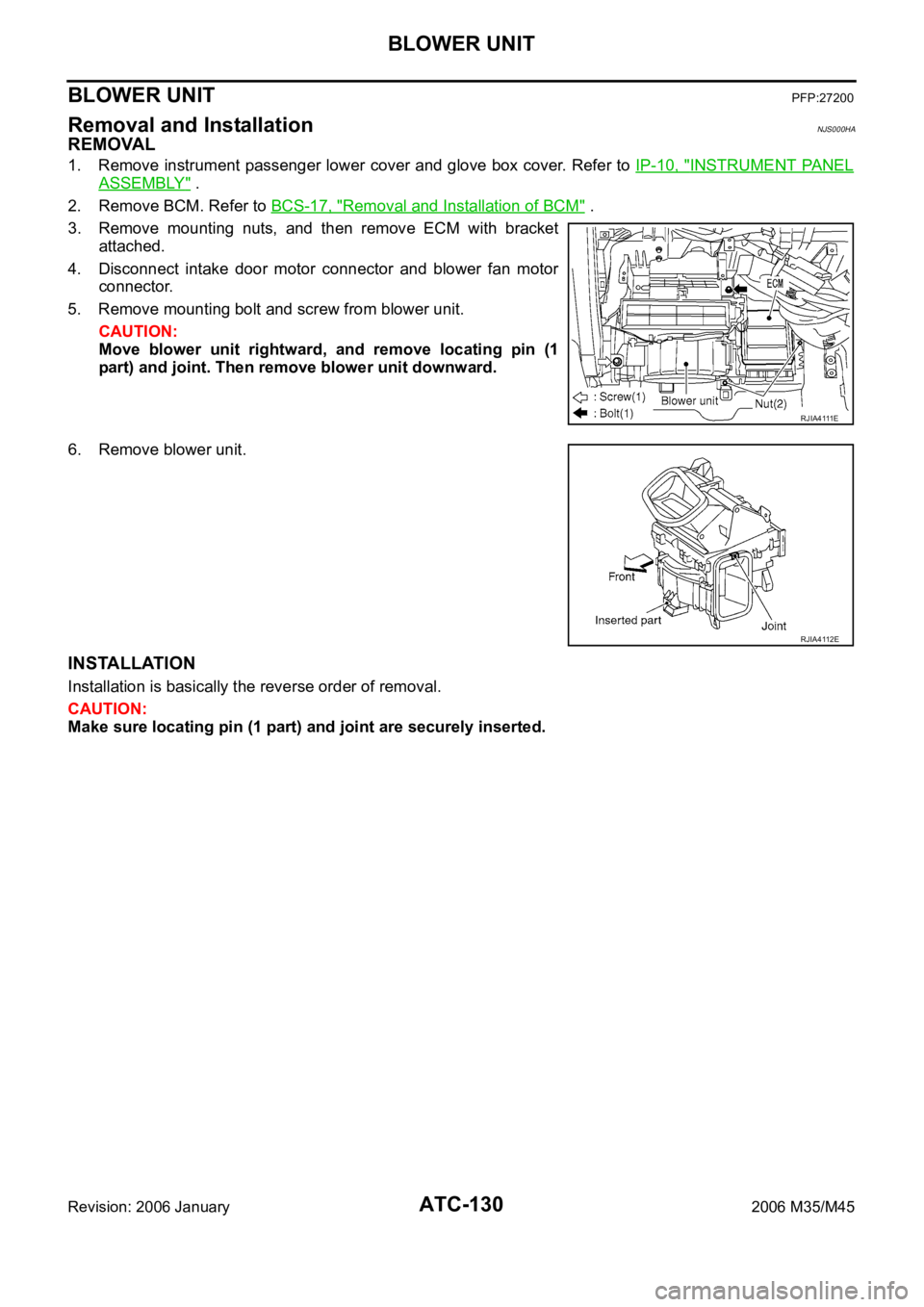
3. Remove mounting nuts, and then remove ECM with bracket
attached.
4. Disconnect intake door motor connector and blower fan motor
connector.
5. Remove mounting bolt and screw from blower unit.
CAUTION:
Move blower unit rightward, and remove locating pin (1
part) and joint. Then remove blower unit downward.
6. Remove blower unit.
INSTALLATION
Installation is basically the reverse order of removal.
CAUTION:
Make sure locating pin (1 part) and joint are securely inserted.
R J I A 4 111 E
RJIA4112E
Page 578 of 5621
 2. In-cabin microfilter 3. Filter cover
4. Intake box (right) 5")
BLOWER UNIT
ATC-131
C
D
E
F
G
H
I
K
L
MA
B
AT C
Revision: 2006 January2006 M35/M45
Disassembly and AssemblyNJS000HB
1. Intake box (left) 2. In-cabin microfilter 3. Filter cover
4. Intake box (right) 5. Intake door lever 2 6. Intake door motor
7. Intake door link 8. Intake door lever 1 9. Intake lower case
10. Blower motor assembly 11. Motor cover 12. Intake upper case
13. Intake door 1 14. Intake door 2
RJIA4113E
Page 579 of 5621

ATC-132
BLOWER MOTOR
Revision: 2006 January2006 M35/M45
BLOWER MOTORPFP:27226
Removal and InstallationNJS000HC
REMOVAL
1. Remove instrument passenger lower cover. Refer to IP-10, "INSTRUMENT PANEL ASSEMBLY" .
2. Disconnect blower motor connector.
3. Remove mounting screws, and then remove blower motor.
INSTALLATION
Installation is basically the reverse order of removal.
RJIA4114E
Page 580 of 5621

INTAKE DOOR MOTOR
ATC-133
C
D
E
F
G
H
I
K
L
MA
B
AT C
Revision: 2006 January2006 M35/M45
INTAKE DOOR MOTORPFP:27730
Removal and InstallationNJS000HD
REMOVAL
1. Remove ECM with bracket attached. Refer to ATC-130, "BLOWER UNIT" .
2. Remove mounting screws, and then remove intake door motor
from blower unit.
3. Disconnect intake door motor connector.
INSTALLATION
Installation is basically the reverse order of removal.
RJIA4115E
Page 585 of 5621

4. Foot duct (left) 5. Ventilator")
ATC-138
HEATER & COOLING UNIT ASSEMBLY
Revision: 2006 January2006 M35/M45
Disassembly and AssemblyNJS000HG
1. Aspirator 2. Aspirator hose 3. Front heater duct (left)
4. Foot duct (left) 5. Ventilator door (left) 6. Ventilator door (right)
7. Foot duct (right) 8. Main link sub (right) 9. Ventilator door lever (right)
10. Ventilator door link (right) 11. Main link (right) 12. Mode door motor (passenger side)
13. Max. cool door link (right) 14. Air mix door motor (passenger side) 15. Intake sensor
16. Intake sensor bracket 17. Low-pressure pipe 1 18. High-pressure pipe 2
19. Expansion valve 20. Cooler pipe grommet 21. Insulator
22. Evaporator cover adapter 23. Air mix door (Slide door) 24. Clip
25. Heater & cooling unit case (left) 26. Heater pipe grommet 27. Heater core
28. Upper ventilator door motor 29. Air mix door motor (driver side) 30. Mode door motor (driver side)
31. Main link (left) 32. Main link sub (left) 33. Ventilator door lever (left)
34. Center case 35. Max. cool door lever (right) 36. Evaporator cover
RJIA4122E
Page 587 of 5621
ATC-140
MODE DOOR MOTOR
Revision: 2006 January2006 M35/M45
MODE DOOR MOTORPFP:27731
Removal and InstallationNJS000HH
REMOVAL
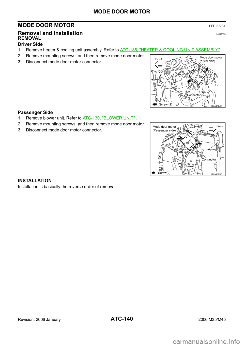
Driver Side
1. Remove heater & cooling unit assembly. Refer to ATC-135, "HEATER & COOLING UNIT ASSEMBLY" .
2. Remove mounting screws, and then remove mode door motor.
3. Disconnect mode door motor connector.
Passenger Side
1. Remove blower unit. Refer to ATC-130, "BLOWER UNIT" .
2. Remove mounting screws, and then remove mode door motor.
3. Disconnect mode door motor connector.
INSTALLATION
Installation is basically the reverse order of removal.
RJIA4124E
RJIA4123E
Page 588 of 5621

AIR MIX DOOR MOTOR
ATC-141
C
D
E
F
G
H
I
K
L
MA
B
AT C
Revision: 2006 January2006 M35/M45
AIR MIX DOOR MOTOR PFP:27732
Removal and InstallationNJS000HI
REMOVAL
Driver Side
1. Set the temperature (driver side) at 18C (60F), and then disconnect the battery cable from the negative
terminal.
2. Remove heater & cooling unit assembly. Refer to ATC-135, "
HEATER & COOLING UNIT ASSEMBLY" .
3. Remove mounting screws, and then remove air mix door motor.
4. Disconnect air mix door motor connector.
Passenger Side
1. Set the temperature (passenger side) at 18C (60F), and then disconnect the battery cable from the neg-
ative terminal.
2. Remove blower unit. Refer to ATC-130, "
BLOWER UNIT" .
3. Remove mounting screws, and then remove air mix door motor.
4. Disconnect air mix door motor connector.
INSTALLATION
Installation is basically the reverse order of removal.
RJIA4126E
RJIA4125E
Page 589 of 5621

ATC-142
UPPER VENTILATOR DOOR MOTOR
Revision: 2006 January2006 M35/M45
UPPER VENTILATOR DOOR MOTORPFP:27731
Removal and InstallationNJS000HJ
REMOVAL
1. Remove heater & cooling unit assembly. Refer to ATC-135, "HEATER & COOLING UNIT ASSEMBLY" .
2. Remove mounting screws.
3. Disconnect upper ventilator door motor connector.
4. Disconnect upper ventilator door rod, and then remove upper
ventilator door motor.
INSTALLATION
Installation is basically the reverse order of removal.
RJIA4127E
Page 596 of 5621
.
2. Remove mounting clips,")
DUCTS AND GRILLES
ATC-149
C
D
E
F
G
H
I
K
L
MA
B
AT C
Revision: 2006 January2006 M35/M45
Removal of Foot Grilles
1. Remove mounting clips, and then remove foot grille (left).
2. Remove mounting clips, and then remove foot grille (right).
Removal of Foot Ducts
1. Remove instrument driver lower panel. Refer to IP-10, "INSTRUMENT PANEL ASSEMBLY" .
2. Remove mounting screws, and then remove heater pipe cover.
3. Remove mounting screws, and then remove foot duct (left).
4. Remove blower unit. Refer to ATC-130, "
BLOWER UNIT" .
5. Remove air mix door motor (passenger side). Refer to ATC-141, "
AIR MIX DOOR MOTOR" .
6. Remove mode door motor (passenger side). Refer to ATC-140, "
MODE DOOR MOTOR" .
7. Remove mounting screws, and then remove evaporator cover.
8. Remove mounting screws, and then remove foot duct (right).
RJIA4143E
RJIA4144E
RJIA4145E
RJIA4146E