stall INFINITI M35 2006 Factory Workshop Manual
[x] Cancel search | Manufacturer: INFINITI, Model Year: 2006, Model line: M35, Model: INFINITI M35 2006Pages: 5621, PDF Size: 65.56 MB
Page 308 of 5621

A/T SHIFT LOCK SYSTEM
AT-229
D
E
F
G
H
I
J
K
L
MA
B
AT
Revision: 2006 January2006 M35/M45
A/T SHIFT LOCK SYSTEMPFP:34950
DescriptionNCS001QP
The mechanical key interlock mechanism also operates as a shift lock:
With the ignition switch turned to ON, the selector lever cannot be shifted from “P” position to any other posi-
tions unless the brake pedal is depressed.
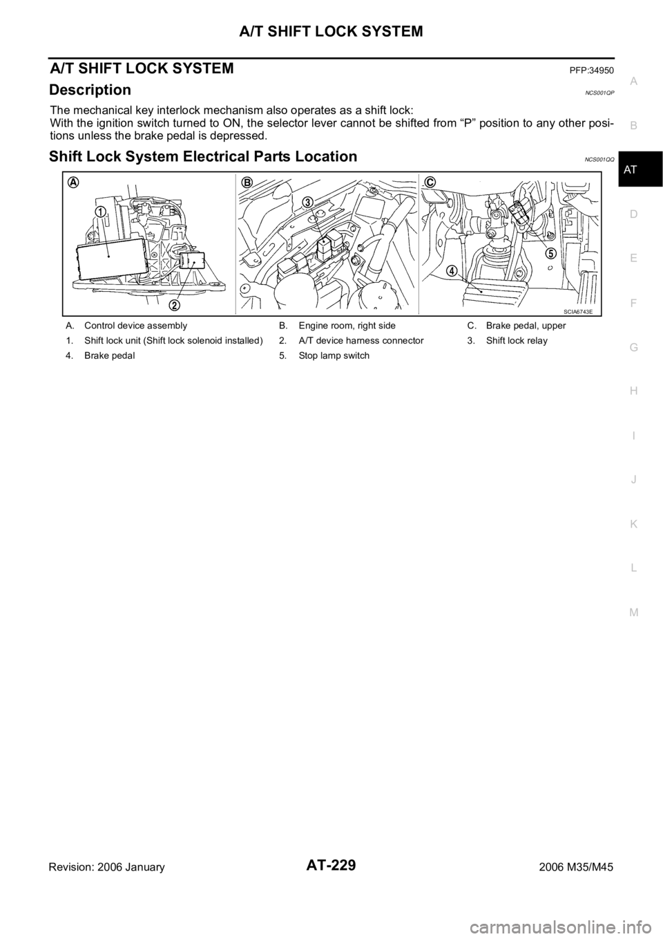
Shift Lock System Electrical Parts LocationNCS001QQ
A. Control device assembly B. Engine room, right side C. Brake pedal, upper
1. Shift lock unit (Shift lock solenoid installed) 2. A/T device harness connector 3. Shift lock relay
4. Brake pedal 5. Stop lamp switch
SCIA6743E
Page 316 of 5621

ON-VEHICLE SERVICE
AT-237
D
E
F
G
H
I
J
K
L
MA
B
AT
Revision: 2006 January2006 M35/M45
CONTROL VALVE WITH TCM REMOVAL AND INSTALLATION
Removal
1. Disconnect the battery cable from the negative terminal.
2. Drain ATF through drain plug.
3. Disconnect heated oxygen sensor 2 harness connector.
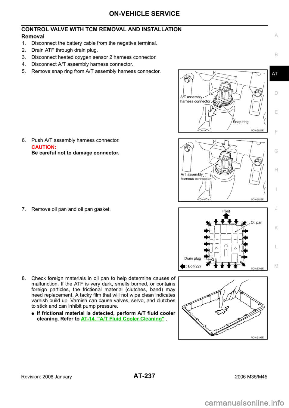
4. Disconnect A/T assembly harness connector.
5. Remove snap ring from A/T assembly harness connector.
6. Push A/T assembly harness connector.
CAUTION:
Be careful not to damage connector.
7. Remove oil pan and oil pan gasket.
8. Check foreign materials in oil pan to help determine causes of
malfunction. If the ATF is very dark, smells burned, or contains
foreign particles, the frictional material (clutches, band) may
need replacement. A tacky film that will not wipe clean indicates
varnish build up. Varnish can cause valves, servo, and clutches
to stick and can inhibit pump pressure.
If frictional material is detected, perform A/T fluid cooler
cleaning. Refer to AT- 1 4 , "
A/T Fluid Cooler Cleaning" .
SCIA5021E
SCIA5022E
SCIA2308E
SCIA5199E
Page 319 of 5621

AT-240
ON-VEHICLE SERVICE
Revision: 2006 January2006 M35/M45
19. Disconnect TCM connectors.
CAUTION:
Be careful not to damage connectors.
20. Remove A/T assembly harness connector from control valve
with TCM using flat-blade screwdriver.
21. Disconnect TCM connector and park/neutral position switch
connector
CAUTION:
Be careful not to damage connectors.
Installation
CAUTION:
After completing installation, check A/T fluid leakage and A/T fluid level. Refer to AT- 1 3 , "
Checking A/T
Fluid" .
1. Connect TCM connector and park/neutral position switch con-
nector.
SCIA5447E
SCIA5448E
SCIA5449E
SCIA5449E
Page 320 of 5621

ON-VEHICLE SERVICE
AT-241
D
E
F
G
H
I
J
K
L
MA
B
AT
Revision: 2006 January2006 M35/M45
2. Install A/T assembly harness connector to control valve with
TCM.
3. Connect TCM connectors.
4. Install new O-ring in A/T assembly harness connector.
CAUTION:
Do not reuse O-ring.
Apply ATF to O-ring.
5. Install A/T fluid temperature sensor 2 to bracket.
6. Install A/T fluid temperature sensor 2 (with bracket) in control
valve with TCM. Tighten A/T fluid temperature sensor 2 bolt to
the specified torque. Refer to AT-236, "
COMPONENTS" .
CAUTION:
Adjust bolt hole of bracket to bolt hole of control valve with
TCM.
SCIA5450E
SCIA5447E
SCIA5155E
SCIA5264E
SCIA5301E
Page 321 of 5621

AT-242
ON-VEHICLE SERVICE
Revision: 2006 January2006 M35/M45
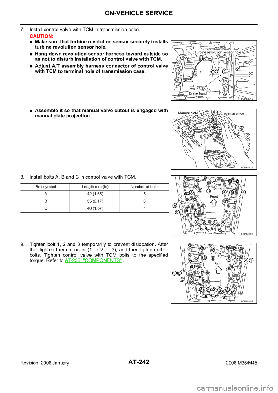
7. Install control valve with TCM in transmission case.
CAUTION:
Make sure that turbine revolution sensor securely installs
turbine revolution sensor hole.
Hang down revolution sensor harness toward outside so
as not to disturb installation of control valve with TCM.
Adjust A/T assembly harness connector of control valve
with TCM to terminal hole of transmission case.
Assemble it so that manual valve cutout is engaged with
manual plate projection.
8. Install bolts A, B and C in control valve with TCM.
9. Tighten bolt 1, 2 and 3 temporarily to prevent dislocation. After
that tighten them in order (1
2 3), and then tighten other
bolts. Tighten control valve with TCM bolts to the specified
torque. Refer to AT-236, "
COMPONENTS" .
SCIA5034E
SCIA5142E
Bolt symbol Length mm (in) Number of bolts
A 42 (1.65) 5
B 55 (2.17) 6
C 40 (1.57) 1
SCIA5139E
SCIA5140E
Page 322 of 5621

ON-VEHICLE SERVICE
AT-243
D
E
F
G
H
I
J
K
L
MA
B
AT
Revision: 2006 January2006 M35/M45
10. Connect A/T fluid temperature sensor 2 connector.
11. Securely fasten terminal cord assembly and A/T fluid tempera-
ture sensor 2 harness with terminal clips.
12. Connect revolution sensor connector.
13. Securely fasten revolution sensor harness with terminal clip.
14. Install magnets in oil pan.
SCIA5023E
SCIA5446E
SCIA7524E
SCIA7525E
SCIA5200E
Page 323 of 5621

AT-244
ON-VEHICLE SERVICE
Revision: 2006 January2006 M35/M45
15. Install oil pan to transmission case.
a. Install oil pan gasket to oil pan.
CAUTION:
Do not reuse oil pan gasket.
Install it in the direction to align hole positions.
Complete remove all moisture, oil and old gasket, etc. from oil pan gasket mounting surface.
b. Install oil pan (with oil pan gasket) to transmission case.
CAUTION:
Install it so that drain plug comes to the position as
shown in the figure.
Be careful not to pinch harnesses.
Completely remove all moisture, oil and old gasket, etc.
from oil pan mounting surface.
c. Tighten oil pan mounting bolts to the specified torque in numeri-
cal order shown in the figure after temporarily tightening them.
Tighten oil pan mounting bolts to the specified torque. Refer to
AT-236, "
COMPONENTS" .
CAUTION:
Do not reuse oil pan mounting bolts.
16. Install drain plug to oil pan. Tighten drain plug to the specified
torque. Refer to AT-236, "
COMPONENTS" .
CAUTION:
Do not reuse drain plug gasket.
17. Pull up A/T assembly harness connector.
CAUTION:
Be careful not to damage connector.
18. Install snap ring to A/T assembly harness connector.
19. Connect A/T assembly harness connector.
20. Connect heated oxygen sensor 2 harness connector.
21. Pour ATF into A/T assembly. Refer to AT- 1 2 , "
Changing A/T
Fluid" .
22. Connect the battery cable to the negative terminal.
SCIA2308E
SCIA4113E
SCIA5038E
SCIA5039E
Page 324 of 5621

ON-VEHICLE SERVICE
AT-245
D
E
F
G
H
I
J
K
L
MA
B
AT
Revision: 2006 January2006 M35/M45
A/T FLUID TEMPERATURE SENSOR 2 REMOVAL AND INSTALLATION
Removal
1. Disconnect the battery cable from the negative terminal.
2. Drain ATF through drain plug.
3. Disconnect heated oxygen sensor 2 harness connector.
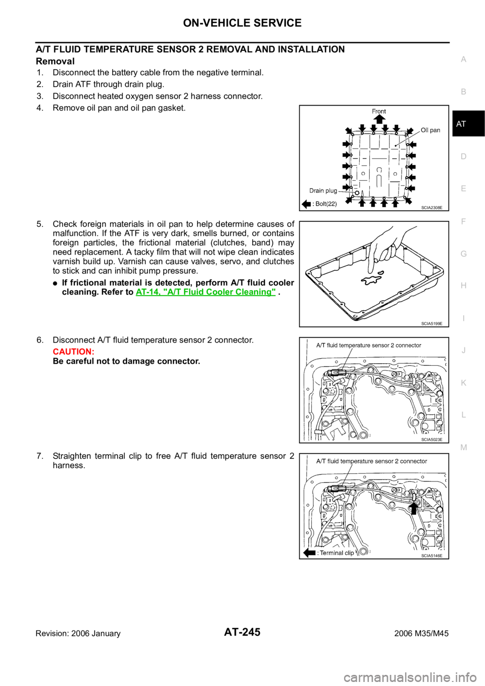
4. Remove oil pan and oil pan gasket.
5. Check foreign materials in oil pan to help determine causes of
malfunction. If the ATF is very dark, smells burned, or contains
foreign particles, the frictional material (clutches, band) may
need replacement. A tacky film that will not wipe clean indicates
varnish build up. Varnish can cause valves, servo, and clutches
to stick and can inhibit pump pressure.
If frictional material is detected, perform A/T fluid cooler
cleaning. Refer to AT- 1 4 , "
A/T Fluid Cooler Cleaning" .
6. Disconnect A/T fluid temperature sensor 2 connector.
CAUTION:
Be careful not to damage connector.
7. Straighten terminal clip to free A/T fluid temperature sensor 2
harness.
SCIA2308E
SCIA5199E
SCIA5023E
SCIA5146E
Page 325 of 5621

AT-246
ON-VEHICLE SERVICE
Revision: 2006 January2006 M35/M45
8. Remove A/T fluid temperature sensor 2 with bracket from con-
trol valve with TCM.
9. Remove bracket from A/T fluid temperature sensor 2.
Installation
CAUTION:
After completing installation, check for A/T fluid leakage and A/T fluid level. Refer to AT- 1 3 , "
Checking
A/T Fluid" .
1. Install A/T fluid temperature sensor 2 to bracket.
2. Install A/T fluid temperature sensor 2 (with bracket) in control
valve with TCM. Tighten A/T fluid temperature sensor 2 bolts to
the specified torque. Refer to AT-236, "
COMPONENTS" .
SCIA5253E
SCIA5264E
SCIA5264E
SCIA5253E
Page 326 of 5621

ON-VEHICLE SERVICE
AT-247
D
E
F
G
H
I
J
K
L
MA
B
AT
Revision: 2006 January2006 M35/M45
3. Connect A/T fluid temperature sensor 2 connector.
4. Securely fasten A/T fluid temperature sensor 2 harness with ter-
minal clip.
5. Install oil pan to transmission case.
a. Install oil pan gasket to oil pan.
CAUTION:
Do not reuse oil pan gasket.
Install it in the direction to align hole positions.
Complete remove all moisture, oil and old gasket, etc. from oil pan gasket mounting surface.
b. Install oil pan (with oil pan gasket) to transmission case.
CAUTION:
Install it so that drain plug comes to the position as
shown in the figure.
Be careful not to pinch harnesses.
Completely remove all moisture, oil and old gasket, etc.
from oil pan mounting surface.
c. Tighten oil pan mounting bolts to the specified torque in numeri-
cal order shown in the figure after temporarily tightening them.
Tighten oil pan mounting bolts to the specified torque. Refer to
AT-236, "
COMPONENTS" .
CAUTION:
Do not reuse oil pan mounting bolts.
6. Install drain plug to oil pan. Tighten drain plug to the specified
torque. Refer to AT-236, "
COMPONENTS" .
CAUTION:
Do not reuse drain plug gasket.
7. Connect heated oxygen sensor 2 harness connector.
8. Pour ATF into A/T assembly. Refer to AT-12, "
Changing A/T Fluid" .
9. Connect the battery cable to the negative terminal.
SCIA5023E
SCIA5146E
SCIA2308E
SCIA4113E