tires INFINITI M35 2006 Factory Workshop Manual
[x] Cancel search | Manufacturer: INFINITI, Model Year: 2006, Model line: M35, Model: INFINITI M35 2006Pages: 5621, PDF Size: 65.56 MB
Page 3509 of 5621

GI-46
TOW TRUCK TOWING
Revision: 2006 January2006 M35/M45
AUTOMATIC TRANSMISSION
To tow a vehicle equipped with an automatic transmission, an appropriate vehicle dolly MUST be placed
under the towed vehicle's drive wheels. Always follow the dolly manufacture's recommendations when using
their product.
If the vehicle is stuck in sand, snow, mud, etc., use the following procedure:
1. Turn off the Vehicle Dynamic Control System.
2. Make sure the area in front and behind the vehicle is clear of obstructions.
3. Turn the steering wheel right and left to clear an area around the front tires.
4. Slowly rock the vehicle forward and backward.
Shift back and forth between R (reverse) and D (drive).
Apply the accelerator as little as possible to maintain the rocking motion.
Release the accelerator pedal before shifting between R and D.
Do not spin the tires above 35 mph (55 km/h).
5. If the vehicle can not be freed after a few tries, contact a professional towing service to remove the vehi-
cle.
Page 3515 of 5621

GI-52
IDENTIFICATION INFORMATION
Revision: 2006 January2006 M35/M45
Dimensions NAS00086
Unit: mm (in)
*1: 2-wheel drive model
*2: All-wheel drive model
Wheels & Tires NAS00087
*: 2-wheel drive modelOverall lengthwithout front license plate 4,893 (192.6)
with front license plate 4,899 (192.9)
Overall width 1,798 (70.8)
Overall height 1,508 (59.4)*1, 1,523 (60.0)*2
Front tread 1,537 (60.5)*1, 1,551 (61.1)*2
Rear tread 1,550 (61.0)*1, 1,543 (60.7)*2
Wheelbase 2,900 (114.2)
Conventional Spare
Road wheel/offset mm (in)18 X 8JJ Aluminum/47 (1.85)
19 X 8.5JJ Aluminum/50 (1.97)*17x4T/30 (1.18)
Tire sizeP245/45R18
245/40R19*T145/80D17
Page 4465 of 5621
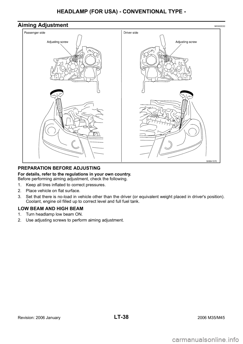
LT-38
HEADLAMP (FOR USA) - CONVENTIONAL TYPE -
Revision: 2006 January2006 M35/M45
Aiming AdjustmentNKS003OG
PREPARATION BEFORE ADJUSTING
For details, refer to the regulations in your own country.
Before performing aiming adjustment, check the following.
1. Keep all tires inflated to correct pressures.
2. Place vehicle on flat surface.
3. Set that there is no-load in vehicle other than the driver (or equivalent weight placed in driver's position).
Coolant, engine oil filled up to correct level and full fuel tank.
LOW BEAM AND HIGH BEAM
1. Turn headlamp low beam ON.
2. Use adjusting screws to perform aiming adjustment.
SKIB4157E
Page 4501 of 5621
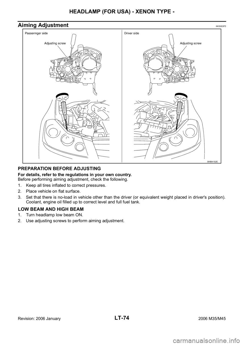
LT-74
HEADLAMP (FOR USA) - XENON TYPE -
Revision: 2006 January2006 M35/M45
Aiming AdjustmentNKS003P5
PREPARATION BEFORE ADJUSTING
For details, refer to the regulations in your own country.
Before performing aiming adjustment, check the following.
1. Keep all tires inflated to correct pressures.
2. Place vehicle on flat surface.
3. Set that there is no-load in vehicle other than the driver (or equivalent weight placed in driver's position).
Coolant, engine oil filled up to correct level and full fuel tank.
LOW BEAM AND HIGH BEAM
1. Turn headlamp low beam ON.
2. Use adjusting screws to perform aiming adjustment.
SKIB4152E
Page 4636 of 5621
FRONT FOG LAMP
LT-209
C
D
E
F
G
H
I
J
L
MA
B
LT
Revision: 2006 January2006 M35/M45
3. CHECK CAN COMMUNICATIONS BETWEEN BCM AND IPDM E/R
Select “BCM” on CONSULT-II, and perform self-diagnosis for “BCM”.
Display of self-diagnosis results
NO DTC>> Replace IPDM E/R. Refer to PG-31, "Removal and
Installation of IPDM E/R" .
CAN COMM CIRCUIT>> Refer to BCS-15, "
CAN Communication
Inspection Using CONSULT-II (Self-Diagnosis)" .
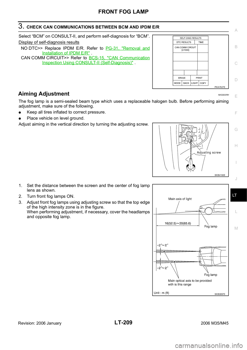
Aiming AdjustmentNKS003RH
The fog lamp is a semi-sealed beam type which uses a replaceable halogen bulb. Before performing aiming
adjustment, make sure of the following.
Keep all tires inflated to correct pressure.
Place vehicle on level ground.
Adjust aiming in the vertical direction by turning the adjusting screw.
1. Set the distance between the screen and the center of fog lamp
lens as shown.
2. Turn front fog lamps ON.
3. Adjust front fog lamps using adjusting screw so that the top edge
of the high intensity zone is in the figure.
When performing adjustment, if necessary, cover the headlamps
and opposite fog lamp.
PKIA7627E
SKIB4160E
SKIB0897E
Page 4782 of 5621

GENERAL MAINTENANCE
MA-5
C
D
E
F
G
H
I
J
K
MA
B
MA
Revision: 2006 January2006 M35/M45
OUTSIDE THE VEHICLE
The maintenance items listed here should be performed from time to time, unless otherwise specified.
INSIDE THE VEHICLE
The maintenance items listed here should be checked on a regular basis, such as when performing periodic maintenance, cleaning the
vehicle, etc.ItemReference page
TiresCheck the pressure with a gauge, including the spare, at least once a month
and always prior to a long distance trips. Adjust to the specified pressure if
necessary. Check carefully for damage, cuts or excessive wear.—
Wheel nutsWhen checking the tires, make sure no nuts are missing, and check for any
loose nuts. Tighten if necessary.—
WindshieldClean the windshield on a regular basis. Check the windshield at least every
six months for cracks or other damage. Repair as necessary.—
Tire rotationTires should be rotated every 12,000 km (7,500 miles).MA-35
Wheel alignment and
balanceIf the vehicle pulls to either side while driving on a straight and level road, or if
you detect uneven or abnormal tire wear, there may be a need for wheel align-
ment. If the steering wheel or seat vibrates at normal highway speeds, wheel
balancing may be needed.MA-33,
FSU-6
(2WD),
FSU-23
(AWD)
Windshield wiper
bladesCheck for cracks or wear if they do not wipe properly. —
Doors and engine
hoodCheck that all doors and the engine hood operate smoothly as well as the
trunk lid. Also make sure that all latches lock securely. Lubricate if necessary.
Make sure that the secondary latch keeps the hood from opening when the pri-
mary latch is released.
When driving in areas using road salt or other corrosive materials, check lubri-
cation frequently.MA-38
LampsMake sure that the headlamps, stop lamps, tail lamps, turn signal lamps, and
other lamps are all operating properly and installed securely. Also check head-
lamp aim. Clean the headlamps on a regular basis. —
ItemReference page
Warning lamps and
chimesMake sure that all warning lamps and chimes are operating properly. —
Windshield wiper and
washerCheck that the wipers and washer operate properly and that the wipers do not
streak.—
Windshield defrosterCheck that the air comes out of the defroster outlets properly and in sufficient
quantity when operating the heater or air conditioner.—
Steering wheelCheck that it has the specified play. Be sure to check for changes in the steer-
ing condition, such as excessive play, hard steering or strange noises.
Free play: Less than 35 mm (1.38 in)—
SeatsCheck seat position controls such as seat adjusters, seatback recliner, etc. to
make sure they operate smoothly and that all latches lock securely in every
position. Check that the head restrains move up and down smoothly and that
the locks (if equipped) hold securely in all latched positions. Check that the
latches lock securely for folding-down rear seatbacks.—
Seat beltsCheck that all parts of the seat belt system (e.g. buckles, anchors, adjusters
and retractors) operate properly and smoothly, and are installed securely.
Check the belt webbing for cuts, fraying, wear or damage.MA-39
Accelerator pedalCheck the pedal for smooth operation and make sure the pedal does not catch
or require uneven effort. Keep the floor mats away from the pedal.—
BrakesCheck that the brake does not pull the vehicle to one side when applied. —
Brake pedal and
boosterCheck the pedal for smooth operation and make sure it has the proper dis-
tance under it when depressed fully. Check the brake booster function. Be
sure to keep the floor mats away from the pedal.BR-6
, BR-18
Page 4812 of 5621
CHASSIS AND BODY MAINTENANCE
MA-35
C
D
E
F
G
H
I
J
K
MA
B
MA
Revision: 2006 January2006 M35/M45
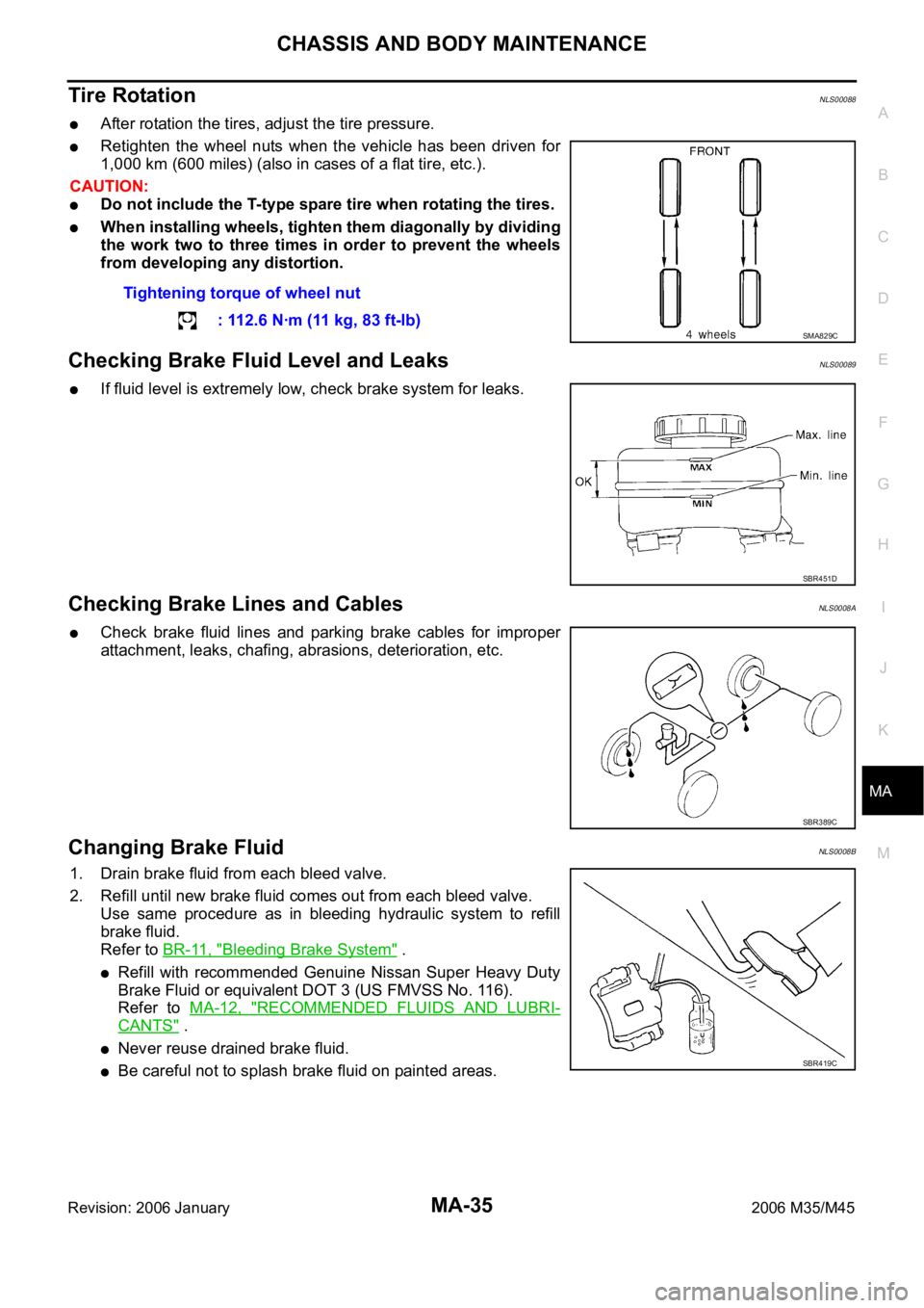
Tire RotationNLS00088
After rotation the tires, adjust the tire pressure.
Retighten the wheel nuts when the vehicle has been driven for
1,000 km (600 miles) (also in cases of a flat tire, etc.).
CAUTION:
Do not include the T-type spare tire when rotating the tires.
When installing wheels, tighten them diagonally by dividing
the work two to three times in order to prevent the wheels
from developing any distortion.
Checking Brake Fluid Level and LeaksNLS00089
If fluid level is extremely low, check brake system for leaks.
Checking Brake Lines and CablesNLS0008A
Check brake fluid lines and parking brake cables for improper
attachment, leaks, chafing, abrasions, deterioration, etc.
Changing Brake FluidNLS0008B
1. Drain brake fluid from each bleed valve.
2. Refill until new brake fluid comes out from each bleed valve.
Use same procedure as in bleeding hydraulic system to refill
brake fluid.
Refer to BR-11, "
Bleeding Brake System" .
Refill with recommended Genuine Nissan Super Heavy Duty
Brake Fluid or equivalent DOT 3 (US FMVSS No. 116).
Refer to MA-12, "
RECOMMENDED FLUIDS AND LUBRI-
CANTS" .
Never reuse drained brake fluid.
Be careful not to splash brake fluid on painted areas.Tightening torque of wheel nut
: 112.6 Nꞏm (11 kg, 83 ft-lb)
SMA829C
SBR451D
SBR389C
SBR419C
Page 4821 of 5621
PB-2
PARKING BRAKE SYSTEM
Revision: 2006 January2006 M35/M45
PARKING BRAKE SYSTEMPFP:36010
On-Vehicle ServiceNFS000PR
PEDAL STROKE
Operate parking brake pedal with a force of 196 N (20 kg, 44 lb), make sure pedal stroke is within the
specified number of notches. (Check it by listening and counting ratchet clicks.)
INSPECT COMPONENTS
Make sure that the mounting conditions (looseness, backlash, etc.) of each component are normal.
Check the following:
–Device assembly for bend, damage and cracks. Replace if there are.
–Cables and equalizer for wear and damage. Replace if there are.
–Parking brake switch. Replace if it does not work correctly.
ADJUSTMENT
To perform adjustment operations, remove rear tires from vehicle with power tool.
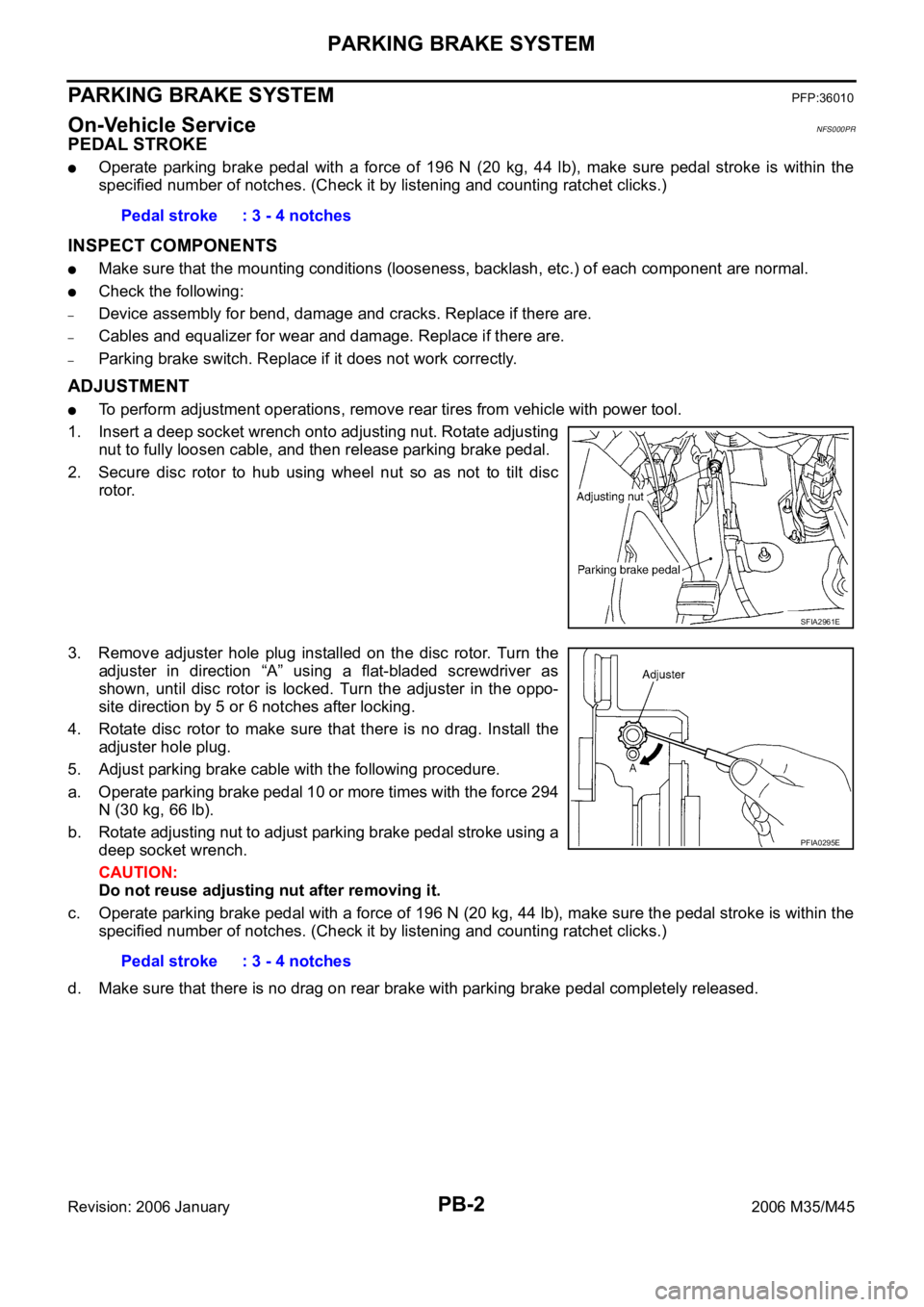
1. Insert a deep socket wrench onto adjusting nut. Rotate adjusting
nut to fully loosen cable, and then release parking brake pedal.
2. Secure disc rotor to hub using wheel nut so as not to tilt disc
rotor.
3. Remove adjuster hole plug installed on the disc rotor. Turn the
adjuster in direction “A” using a flat-bladed screwdriver as
shown, until disc rotor is locked. Turn the adjuster in the oppo-
site direction by 5 or 6 notches after locking.
4. Rotate disc rotor to make sure that there is no drag. Install the
adjuster hole plug.
5. Adjust parking brake cable with the following procedure.
a. Operate parking brake pedal 10 or more times with the force 294
N (30 kg, 66 lb).
b. Rotate adjusting nut to adjust parking brake pedal stroke using a
deep socket wrench.
CAUTION:
Do not reuse adjusting nut after removing it.
c. Operate parking brake pedal with a force of 196 N (20 kg, 44 lb), make sure the pedal stroke is within the
specified number of notches. (Check it by listening and counting ratchet clicks.)
d. Make sure that there is no drag on rear brake with parking brake pedal completely released. Pedal stroke : 3 - 4 notches
SFIA2961E
Pedal stroke : 3 - 4 notches
PFIA0295E
Page 4823 of 5621

PB-4
PARKING BRAKE CONTROL
Revision: 2006 January2006 M35/M45
Removal and InstallationNFS000PT
REMOVAL
1. Remove rear tires from vehicle with power tool.
2. Remove instrument driver lower panel. Refer to IP-10, "
INSTRUMENT PANEL ASSEMBLY" .
3. Disconnect parking brake switch connector.
4. Remove adjusting nut and loosen front cable.
5. Remove device assembly mounting nuts and remove device assembly from vehicle.
6. Remove center console. Refer to IP-19, "
CENTER CONSOLE ASSEMBLY" .
7. Separate rear cable from front cable, remove front cable from vehicle.
8. Remove heat insulator of the exhaust center tube from vehicle.
9. Remove parking brake shoe, and remove rear cable from toggle lever. Refer to PB-6, "
Removal and
Installation" .
10. Remove rear cable mounting bolts and nuts, pull out rear cable from vehicle.
INSTALLATION
1. Install in the reverse order of the removal. Refer to PB-3, "Components" for tightening torque.
CAUTION:
Do not reuse adjusting nut.
2. Adjust parking brake. Refer to PB-2, "
ADJUSTMENT" .
Page 4825 of 5621
PB-6
PARKING BRAKE SHOE
Revision: 2006 January2006 M35/M45
Removal and InstallationNFS000PV
REMOVAL
WAR NING :
Clean brakes with a vacuum dust collector to minimize the hazard of air borne particles or other mate-
rials.
CAUTION:
Clean dust on disc rotor and back plate using a vacuum dust collector. Do not blow with com-
pressed air.
Put matching marks on both disc rotor and wheel hub when removing disc rotor.
1. Remove rear tires from vehicle with power tool.
2. Remove disc rotor with parking brake pedal completely in the released position. Refer to BR-31,
"Removal and Installation of Brake Caliper Assembly" .
3. If disc rotor cannot be removed, remove as follows:
a. Secure the disc rotor in place with wheel nuts and remove adjuster hole plug.
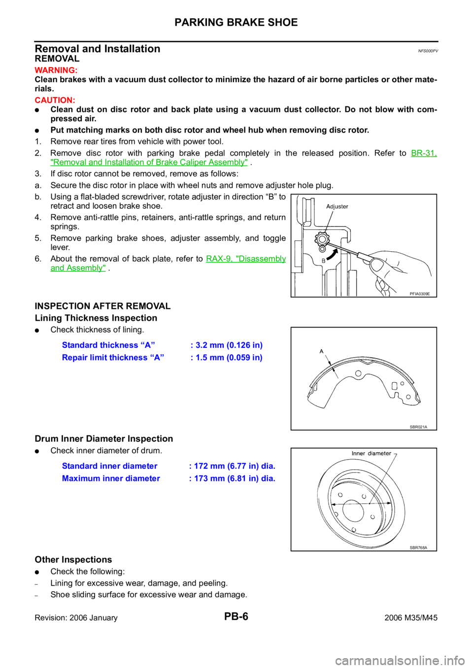
b. Using a flat-bladed screwdriver, rotate adjuster in direction “B” to
retract and loosen brake shoe.
4. Remove anti-rattle pins, retainers, anti-rattle springs, and return
springs.
5. Remove parking brake shoes, adjuster assembly, and toggle
lever.
6. About the removal of back plate, refer to RAX-9, "
Disassembly
and Assembly" .
INSPECTION AFTER REMOVAL
Lining Thickness Inspection
Check thickness of lining.
Drum Inner Diameter Inspection
Check inner diameter of drum.
Other Inspections
Check the following:
–Lining for excessive wear, damage, and peeling.
–Shoe sliding surface for excessive wear and damage.
PFIA0309E
Standard thickness “A” : 3.2 mm (0.126 in)
Repair limit thickness “A” : 1.5 mm (0.059 in)
SBR021A
Standard inner diameter : 172 mm (6.77 in) dia.
Maximum inner diameter : 173 mm (6.81 in) dia.
SBR768A