turn signal INFINITI M35 2006 Factory Workshop Manual
[x] Cancel search | Manufacturer: INFINITI, Model Year: 2006, Model line: M35, Model: INFINITI M35 2006Pages: 5621, PDF Size: 65.56 MB
Page 313 of 5621

AT-234
A/T SHIFT LOCK SYSTEM
Revision: 2006 January2006 M35/M45
5. CHECK INPUT SIGNAL A/T DEVICE
1. Turn ignition switch OFF.
2. Disconnect A/T device harness connector.
3. Turn ignition switch ON. (Do not start engine.)
4. Check voltage between A/T device harness connector M133 ter-
minal 7 and ground.
OK or NG
OK >> GO TO 7.
NG >> GO TO 6.
6. DETECT MALFUNCTIONING ITEM
Check the following.
Harness for short or open between push-button ignition switch and shift lock relay E35 terminal 5
Harness for short or open between shift lock relay E35 terminal 3 and A/T device harness connector
M133 terminal 7
10A fuse [No.12, located in the fuse block (J/B)]
Push-button ignition switch (Refer to PG-3, "POWER SUPPLY ROUTING CIRCUIT" .)
Shift lock relay
–Check continuity between shift lock relay E35 terminal 3 and 5
OK or NG
OK >> GO TO 7.
NG >> Repair or replace damaged parts.
7. CHECK GROUND CIRCUIT
1. Turn ignition switch OFF.
2. Disconnect A/T device harness connector.
3. Check continuity between A/T device harness connector M133
terminal 8 and ground.
If OK, check harness for short to ground and short to power.
OK or NG
OK >> GO TO 8.
NG >> Repair open circuit or short to ground or short to power
in harness or connectors. Vo l ta g e
Brake pedal depressed: Battery voltage
Brake pedal released: 0V
SCIA6867E
Condition Continuity
12V direct current supply between terminal 1 and 2 Yes
OFF No
SCIA1245E
Continuity should exist.
SCIA6868E
Page 477 of 5621

ATC-30
AIR CONDITIONER CONTROL
Revision: 2006 January2006 M35/M45
OPERATION
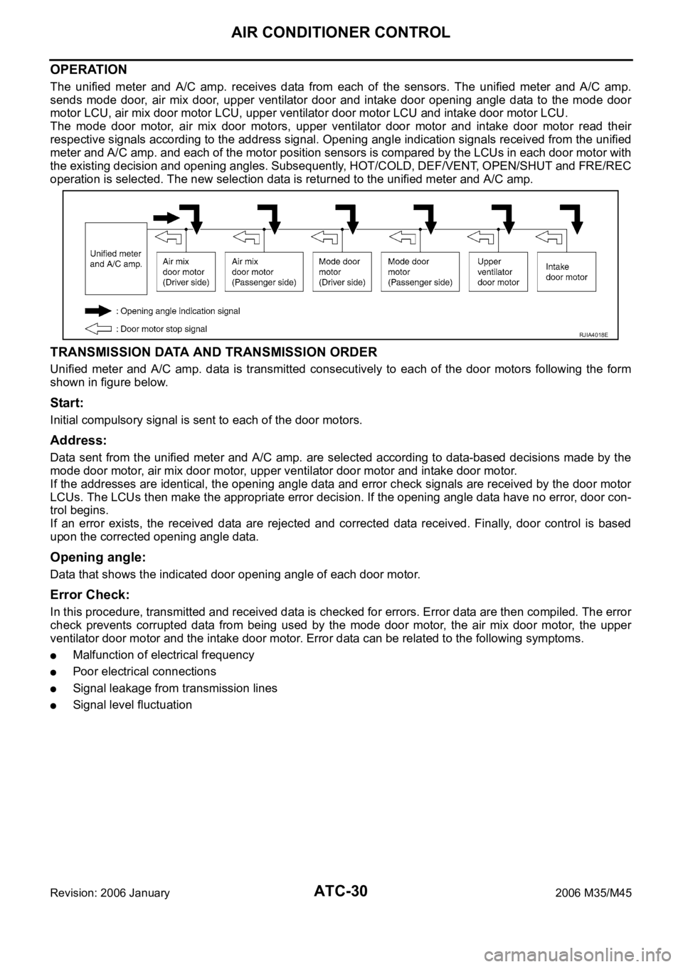
The unified meter and A/C amp. receives data from each of the sensors. The unified meter and A/C amp.
sends mode door, air mix door, upper ventilator door and intake door opening angle data to the mode door
motor LCU, air mix door motor LCU, upper ventilator door motor LCU and intake door motor LCU.
The mode door motor, air mix door motors, upper ventilator door motor and intake door motor read their
respective signals according to the address signal. Opening angle indication signals received from the unified
meter and A/C amp. and each of the motor position sensors is compared by the LCUs in each door motor with
the existing decision and opening angles. Subsequently, HOT/COLD, DEF/VENT, OPEN/SHUT and FRE/REC
operation is selected. The new selection data is returned to the unified meter and A/C amp.
TRANSMISSION DATA AND TRANSMISSION ORDER
Unified meter and A/C amp. data is transmitted consecutively to each of the door motors following the form
shown in figure below.
Start:
Initial compulsory signal is sent to each of the door motors.
Address:
Data sent from the unified meter and A/C amp. are selected according to data-based decisions made by the
mode door motor, air mix door motor, upper ventilator door motor and intake door motor.
If the addresses are identical, the opening angle data and error check signals are received by the door motor
LCUs. The LCUs then make the appropriate error decision. If the opening angle data have no error, door con-
trol begins.
If an error exists, the received data are rejected and corrected data received. Finally, door control is based
upon the corrected opening angle data.
Opening angle:
Data that shows the indicated door opening angle of each door motor.
Error Check:
In this procedure, transmitted and received data is checked for errors. Error data are then compiled. The error
check prevents corrupted data from being used by the mode door motor, the air mix door motor, the upper
ventilator door motor and the intake door motor. Error data can be related to the following symptoms.
Malfunction of electrical frequency
Poor electrical connections
Signal leakage from transmission lines
Signal level fluctuation
RJIA4018E
Page 479 of 5621

ATC-32
AIR CONDITIONER CONTROL
Revision: 2006 January2006 M35/M45
MAGNET CLUTCH CONTROL
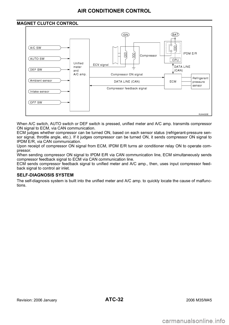
When A/C switch, AUTO switch or DEF switch is pressed, unified meter and A/C amp. transmits compressor
ON signal to ECM, via CAN communication.
ECM judges whether compressor can be turned ON, based on each sensor status (refrigerant-pressure sen-
sor signal, throttle angle, etc.). If it judges compressor can be turned ON, it sends compressor ON signal to
IPDM E/R, via CAN communication.
Upon receipt of compressor ON signal from ECM, IPDM E/R turns air conditioner relay ON to operate com-
pressor.
When sending compressor ON signal to IPDM E/R via CAN communication line, ECM simultaneously sends
compressor feedback signal to ECM via CAN communication line.
ECM sends compressor feedback signal to unified meter and A/C amp., then, uses input compressor feed-
back signal to control air inlet.
SELF-DIAGNOSIS SYSTEM
The self-diagnosis system is built into the unified meter and A/C amp. to quickly locate the cause of malfunc-
tions.
RJIA4020E
Page 517 of 5621

ATC-70
TROUBLE DIAGNOSIS
Revision: 2006 January2006 M35/M45
LAN System CircuitNJS000GN
SYMPTOM: Mode door motors, upper ventilator door motor, air mix door motors and intake door motor does
not operate normally.
DIAGNOSIS PROCEDURE FOR LAN CIRCUIT
1. CHECK POWER SUPPLY FOR UNIFIED METER AND A/C AMP.
1. Turn ignition switch ON.
2. Check voltage between unified meter and A/C amp. harness
connector M65 terminal 70 and ground.
OK or NG
OK >> GO TO 2.
NG >> Replace unified meter and A/C amp.
2. CHECK SIGNAL FOR UNIFIED METER AND A/C AMP.
Confirm A/C LAN signal between unified meter and A/C amp. har-
ness connector M65 terminal 69 and ground using an oscilloscope.
OK or NG
OK >> GO TO 3.
NG >> Replace unified meter and A/C amp.
RJIA4052E
70 – Ground : Battery voltage
RJIA4053E
Terminals
Voltage (+)
(
)
Unified meter and
A/C amp. connectorTe r m i n a l N o .
M65 69 Ground
RJIA4054E
SJIA1453J
Page 518 of 5621

TROUBLE DIAGNOSIS
ATC-71
C
D
E
F
G
H
I
K
L
MA
B
AT C
Revision: 2006 January2006 M35/M45
3. CHECK POWER SUPPLY FOR EACH DOOR MOTOR
Check voltage between each door motor harness connector terminal
1 and ground.
OK or NG
OK >> GO TO 4.
NG >> Repair harness or connector.
4. CHECK SIGNAL FOR EACH DOOR MOTOR
Confirm A/C LAN signal between each door motor harness connec-
tor terminal 3 and ground using an oscilloscope.
OK or NG
OK >> GO TO 5.
NG >> Repair harness or connector.
5. CHECK MOTOR GROUND CIRCUIT
1. Turn ignition switch OFF.
2. Disconnect each door motor connector.
3. Check continuity between each door motor harness connector
terminal 2 and ground.
OK or NG
OK >> GO TO 6.
NG >> Repair harness or connector.1 – Ground : Battery voltage
RJIA1988E
Door motorTerminals
Voltag e (+)
()
Con-
nectorTerminal
No.
Mode (Driver
side)M252 3
Ground Mode (Pas-
senger side)M255 3
Upper venti-
latorM254 3
Air mix
(Driver side)M253 3
Air mix (Pas-
senger side)M256 3
Intake M257 3
RJIA1989E
SJIA1453J
2 – Ground : Continuity should exist.
RJIA1990E
Page 525 of 5621

ATC-78
TROUBLE DIAGNOSIS
Revision: 2006 January2006 M35/M45
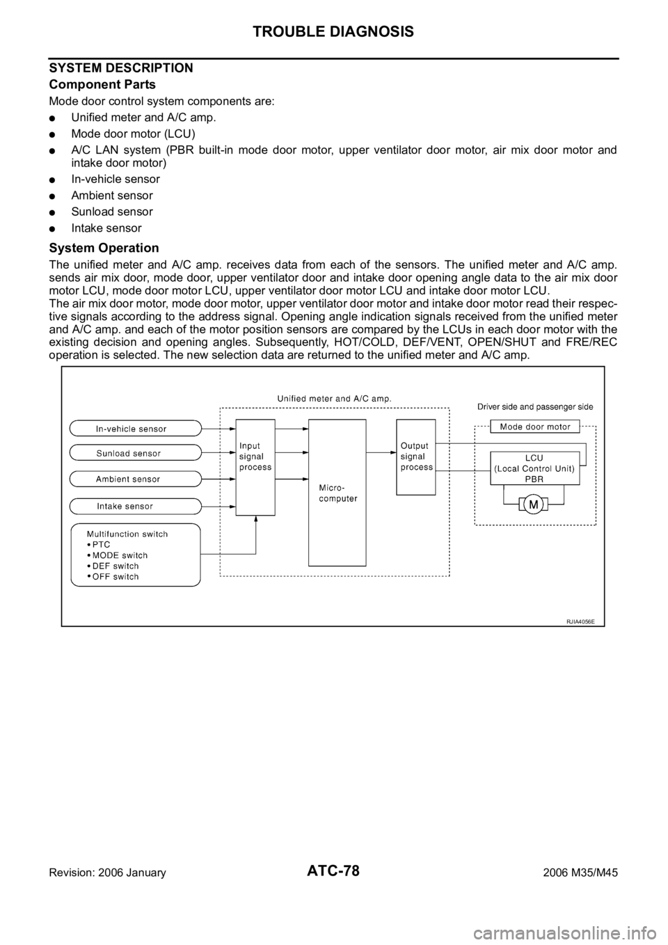
SYSTEM DESCRIPTION
Component Parts
Mode door control system components are:
Unified meter and A/C amp.
Mode door motor (LCU)
A/C LAN system (PBR built-in mode door motor, upper ventilator door motor, air mix door motor and
intake door motor)
In-vehicle sensor
Ambient sensor
Sunload sensor
Intake sensor
System Operation
The unified meter and A/C amp. receives data from each of the sensors. The unified meter and A/C amp.
sends air mix door, mode door, upper ventilator door and intake door opening angle data to the air mix door
motor LCU, mode door motor LCU, upper ventilator door motor LCU and intake door motor LCU.
The air mix door motor, mode door motor, upper ventilator door motor and intake door motor read their respec-
tive signals according to the address signal. Opening angle indication signals received from the unified meter
and A/C amp. and each of the motor position sensors are compared by the LCUs in each door motor with the
existing decision and opening angles. Subsequently, HOT/COLD, DEF/VENT, OPEN/SHUT and FRE/REC
operation is selected. The new selection data are returned to the unified meter and A/C amp.
RJIA4056E
Page 528 of 5621

TROUBLE DIAGNOSIS
ATC-81
C
D
E
F
G
H
I
K
L
MA
B
AT C
Revision: 2006 January2006 M35/M45
SYSTEM DESCRIPTION
Component Parts
Upper ventilator door control system components are:
Unified meter and A/C amp.
Upper ventilator door motor (LCU)
A/C LAN system (PBR built-in mode door motor, upper ventilator door motor, air mix door motor and
intake door motor)
Sunload sensor
System Operation
The unified meter and A/C amp. receives data from each of the sensors. The unified meter and A/C amp.
sends air mix door, mode door, upper ventilator door and intake door opening angle data to the air mix door
motor LCU, mode door motor LCU, upper ventilator door motor LCU and intake door motor LCU.
The air mix door motor, mode door motor, upper ventilator door motor and intake door motor read their respec-
tive signals according to the address signal. Opening angle indication signals received from the unified meter
and A/C amp. and each of the motor position sensors are compared by the LCUs in each door motor with the
existing decision and opening angles. Subsequently, HOT/COLD, DEF/VENT, OPEN/SHUT and FRE/REC
operation is selected. The new selection data are returned to the unified meter and A/C amp.
RJIA4060E
Page 531 of 5621

ATC-84
TROUBLE DIAGNOSIS
Revision: 2006 January2006 M35/M45
SYSTEM DESCRIPTION
Component Parts
Air mix door control system components are:
Unified meter and A/C amp.
Air mix door motor (LCU)
A/C LAN system (PBR built-in mode door motor, upper ventilator door motor, air mix door motor and
intake door motor)
In-vehicle sensor
Ambient sensor
Sunload sensor
Intake sensor
System Operation
The unified meter and A/C amp. receives data from each of the sensors. The unified meter and A/C amp.
sends air mix door, mode door, upper ventilator door and intake door opening angle data to the air mix door
motor LCUs, mode door motor LCUs, upper ventilator door motor LCU and intake door motor LCU.
The air mix door motors, mode door motors, upper ventilator door motor and intake door motor read their
respective signals according to the address signal. Opening angle indication signals received from the unified
meter and A/C amp. and each of the motor position sensors are compared by the LCUs in each door motor
with the existing decision and opening angles. Subsequently, HOT/COLD, DEF/VENT, OPEN/SHUT and FRE/
REC operation is selected. The new selection data are returned to the unified meter and A/C amp.
Air Mix Door Control Specification
RJIA4217E
RJIA1782E
Page 540 of 5621

TROUBLE DIAGNOSIS
ATC-93
C
D
E
F
G
H
I
K
L
MA
B
AT C
Revision: 2006 January2006 M35/M45
4. CHECK UNIFIED METER AND A/C AMP. OUTPUT SIGNAL
1. Reconnect blower motor connector and unified meter and A/C
amp. connector.
2. Turn ignition switch ON.
3. Change the fan speed from Lo to Hi, and check the duty ratios
between blower motor harness connector M91 terminal 2 and
ground by using an oscilloscope. Normal terminal 2 drive signal
duty ratios are shown in the table below.
OK or NG
OK >> Replace blower motor after confirming the fan air flow does not change.
NG >> Replace unified meter and A/C amp.
COMPONENT INSPECTION
Blower Motor
Confirm smooth rotation of the blower motor.
Ensure that there are no foreign particles inside the blower unit.
RJIA4074E
RJIA4075E
RJIA4076E
Page 542 of 5621

TROUBLE DIAGNOSIS
ATC-95
C
D
E
F
G
H
I
K
L
MA
B
AT C
Revision: 2006 January2006 M35/M45
SYSTEM DESCRIPTION
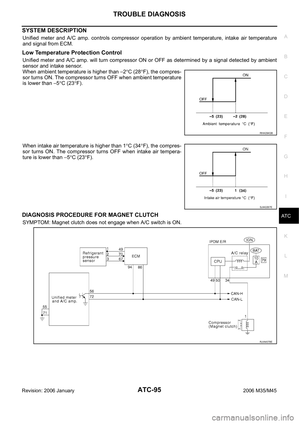
Unified meter and A/C amp. controls compressor operation by ambient temperature, intake air temperature
and signal from ECM.
Low Temperature Protection Control
Unified meter and A/C amp. will turn compressor ON or OFF as determined by a signal detected by ambient
sensor and intake sensor.
When ambient temperature is higher than
2C (28F), the compres-
sor turns ON. The compressor turns OFF when ambient temperature
is lower than
5C (23F).
When intake air temperature is higher than 1
C (34F), the compres-
sor turns ON. The compressor turns OFF when intake air tempera-
ture is lower than
5C (23F).
DIAGNOSIS PROCEDURE FOR MAGNET CLUTCH
SYMPTOM: Magnet clutch does not engage when A/C switch is ON.
RHA094GB
SJIA0267E
RJIA4078E