horn INFINITI M35 2006 Factory Service Manual
[x] Cancel search | Manufacturer: INFINITI, Model Year: 2006, Model line: M35, Model: INFINITI M35 2006Pages: 5621, PDF Size: 65.56 MB
Page 1 of 5621
A
B
C
D
E
F
G
H
I
J
K
M
L
QUICK REFERENCE INDEX
AGENERAL INFORMATIONGIGeneral Information
BENGINEEMEngine Mechanical
LUEngine Lubrication System
COEngine Cooling System
ECEngine Control System
FLFuel System
EXExhaust System
ACCAccelerator Control System
CTRANSMISSION/
TRANSAXLEATAutomatic Transmission
DDRIVELINE/AXLETFTransfer
PRPropeller Shaft
FFDFront Final Drive
RFDRear Final Drive
FAXFront Axle
RAXRear Axle
ESUSPENSIONFSUFront Suspension
RSURear Suspension
WTRoad Wheels & Tires
FBRAKESBRBrake System
PBParking Brake System
BRCBrake Control System
GSTEERINGPSPower Steering System
STCSteering Control System
HRESTRAINTSSBSeat Belts
SRSSupplemental Restraint System
(SRS)
IBODYBLBody, Lock & Security System
GWGlasses, Window System & Mir-
rors
RFRoof
EIExterior & Interior
IPInstrument Panel
SESeat
JAIR CONDITIONERATCAutomatic Air Conditioner
KELECTRICALSCStarting & Charging System
LTLighting System
DIDriver Information System
WWWiper, Washer & Horn
BCSBody Control System
LANLAN System
AVAudio-Visual System
ACSAuto Cruise Control System
PGPower Supply, Ground & Circuit Ele-
ments
LMAINTENANCEMAMaintenance
MINDEXIDXAlphabetical Index
Edition: January 2005
Revision: January 2006
Page 941 of 5621

BL-2Revision: 2006 January2006 M35/M45 CHANGE SETTINGS FUNCTION ....................... 60
INTELLIGENT KEY REGISTRATION .................. 60
STEERING LOCK UNIT REGISTRATION .......... 60
CAN Communication System Description .............. 60
CAN Communication Unit ....................................... 60
Schematic ............................................................... 61
Wiring Diagram — I/KEY— .................................... 63
Terminals and Reference Value for Intelligent Key
Unit ......................................................................... 74
Terminals and Reference Value for BCM ................ 77
Terminals and Reference Value for IPDM E/R ........ 77
Trouble Diagnosis Procedure ................................. 78
WORK FLOW ...................................................... 78
CONSULT-II Functions (INTELLIGENT KEY) ........ 80
CONSULT-II Inspection Procedure ......................... 80
BASIC OPERATION ............................................ 80
CONSULT-II Application Items ............................... 81
SELF-DIAGNOSTIC RESULTS ........................... 81
DATA MONITOR .................................................. 82
WORK SUPPORT ............................................... 83
ACTIVE TEST ..................................................... 84
Trouble Diagnosis Symptom Chart ......................... 86
ALL FUNCTIONS OF INTELLIGENT KEY SYS-
TEM DOES NOT OPERATE ............................... 86
DOOR LOCK/UNLOCK FUNCTION MALFUNC-
TION .................................................................... 86
REMOTE KEYLESS ENTRY FUNCTION MAL-
FUNCTION .......................................................... 87
TRUNK OPEN FUNCTION MALFUNCTION ...... 88
HAZARD AND BUZZER REMINDER FUNC-
TION MALFUNCTION ......................................... 89
HAZARD AND HORN REMINDER FUNCTION
MALFUNCTION ................................................... 89
POWER WINDOW DOWN FUNCTION MAL-
FUNCTION .......................................................... 90
WARNING FUNCTION MALFUNCTION ............. 90
Check CAN Communication System ...................... 92
Check Power Supply and Ground Circuit ............... 93
Check Key Slot ....................................................... 94
Check Door Switch ..............................................
... 96
Check Trunk Room Lamp Switch ........................... 99
Check Door Request Switch .................................101
Check Trunk Opener Request Switch ..................103
Check Unlock Sensor ...........................................105
Check Intelligent Key Warning Buzzer .................107
Check Outside Key Antenna (Driver Side and Pas-
senger Side) .........................................................108
Check Outside Key Antenna (Trunk Room) .........110
Check Inside Key Antenna ...................................112
Check Park Position Switch ..................................115
Check Ignition Switch Position .............................117
Check Remote Keyless Entry Receiver ................117
Check Trunk Lid Opener Cancel Switch ...............121
Check Key Slot Illumination ..................................123
Check Horn Function ............................................124
Check Combination Meter Display Function .........124
Check Warning Chime Function ...........................125
Removal and Installation of Intelligent Key Unit ...125
REMOVAL ........................................................
.125INSTALLATION ..................................................125
Intelligent Key Battery Replacement .....................126
DISASSEMBLY AND ASSEMBLY OF INTELLI-
GENT KEY .........................................................126
INTELLIGENT KEY BATTERY INSPECTION ...126
INTELLIGENT KEY SYSTEM/ENGINE START
FUNCTION ..............................................................127
Component Parts and Harness Connector Location .127
System Description ...............................................128
PRECAUTIONS FOR INTELLIGENT KEY SYS-
TEM ...................................................................129
Operation Description ...........................................129
SYSTEM DIAGRAM ..........................................129
OPERATION WHEN INTELLIGENT KEY IS
CARRIED ...........................................................129
OPERATION WHEN KEY SLOT IS USED ........130
PUSH-BUTTON IGNITION SWITCH OPERA-
TION PROCEDURE ..........................................130
CAN Communication System Description ............131
CAN Communication Unit .....................................131
Schematic .............................................................132
Wiring Diagram —ENG/ST— ................................134
Terminals and Reference Value for Intelligent Key
Unit ........................................................................143
Terminals and Reference Value for Steering Lock
Unit ........................................................................146
Terminals and Reference Value for BCM ..............147
Terminals and Reference Value for IPDM E/R ......147
Terminals and Reference Value for PDU ..............148
Work Flow .............................................................149
CONSULT-II Functions (INTELLIGENT KEY) .......151
CONSULT-II Inspection Procedure .......................151
BASIC OPERATION ..........................................151
CONSULT-II Application Items ..............................152
SELF-DIAGNOSTIC RESULTS .........................152
DATA MONITOR ................................................153
WORK SUPPORT .............................................154
ACTIVE TEST ....................................................155
DTC B2013 STRG COMM 1 .................................157
DIAGNOSIS DESCRIPTION .............................157
TERMINALS AND REFERENCE VALUE FOR
INTELLIGENT KEY UNIT ..................................157
SELF-DIAGNOSTIC LOGIC ..............................157
DIAGNOSTIC PROCEDURE .............................157
DTC B2551 STEERING LOCK UNIT ....................159
DIAGNOSIS DESCRIPTION .............................159
TERMINALS AND REFERENCE VALUE ..........159
SELF-DIAGNOSTIC LOGIC .............................
.160
DIAGNOSTIC PROCEDURE .............................160
DTC B2552 INTELLIGENT KEY ...........................163
DIAGNOSIS DESCRIPTION .............................163
DTC B2553 IGN POWER CIRCUIT ......................163
DIAGNOSIS DESCRIPTION .............................163
TERMINAL AND REFERENCE VALUE FOR
INTELLIGENT KEY UNIT ..................................163
CONSULT-II DATA MONITOR STANDARD
VALUE ...............................................................163
SELF-DIAGNOSTIC LOGIC ..............................164
DIAGNOSTIC PROCEDURE .............................164
Page 943 of 5621

BL-4Revision: 2006 January2006 M35/M45 Terminals and Reference Value for BCM ..............213
CONSULT-II Function (BCM) ................................214
CONSULT-II INSPECTION PROCEDURE ........214
DATA MONITOR ................................................215
ACTIVE TEST ...................................................215
Trouble Diagnosis .................................................216
TRUNK DOSE NOT OPEN WITH TRUNK LID
OPENER SWITCH / WITH INTELLIGENT KEY .216
VEHICLE SECURITY (THEFT WARNING) SYSTEM .220
Component Parts and Harness Connector Location .220
System Description ...............................................222
DESCRIPTION ..................................................222
POWER SUPPLY AND GROUND CIRCUIT .....223
INITIAL CONDITION TO ACTIVATE THE SYS-
TEM ...................................................................223
VEHICLE SECURITY SYSTEM ALARM OPER-
ATION ................................................................224
VEHICLE SECURITY SYSTEM DEACTIVATION .224
PANIC ALARM OPERATION .............................224
CAN Communication System Description ............224
CAN Communication Unit .....................................224
Schematic .............................................................225
Wiring Diagram —VEHSEC— ..............................226
Terminals and Reference Value of BCM ...............232
Terminals and Reference Value of IPDM E/R .......232
CONSULT-II Function (BCM) ................................233
CONSULT-II APPLICATION ITEM .....................234
Trouble Diagnosis Work Flow ...............................235
Preliminary Check ................................................235
Trouble Diagnosis Symptom Chart .......................237
Diagnostic Procedure 1 ........................................238
DOOR SWITCH CHECK ...................................238
HOOD SWITCH CHECK ...................................241
TRUNK ROOM LAMP SWITCH CHECK ..........243
Diagnostic Procedure 2 ........................................245
SECURITY INDICATOR LAMP CHECK ............245
Diagnostic Procedure 3 ........................................246
FRONT DOOR KEY CYLINDER SWITCH
CHECK ..............................................................246
Diagnostic Procedure 4 ........................................246
VEHICLE SECURITY HORN ALARM CHECK . 246
Diagnostic Procedure 5 ........................................247
VEHICLE SECURITY HEADLAMP ALARM
CHECK ..............................................................247
Diagnostic Procedure 6 ........................................247
DOOR LOCK AND UNLOCK SWITCH CHECK .247
Diagnostic Procedure 7 ........................................247
VEHCLE SECURITY HAZARD LAMP ALARM
CHECK ..............................................................247
IVIS (INFINITI VEHICLE IMMOBILIZER SYSTEM-
NATS) ......................................................................248
Component Parts and Harness Connector Location .248
System Description ...............................................250
DESCRIPTION ..................................................250
PRECAUTIONS FOR KEY REGISTRATION ....250
SECURITY INDICATOR ....................................250
Operation Description ...........................................251
SYSTEM DIAGRAM ..........................................251
OPERATION WHEN INSERTING TO KEY SLOT .251OPERATION WHEN INTELLIGENT KEY IS
CARRIED ...........................................................251
PUSH-BUTTON IGNITION SWITCH OPERA-
TION PROCEDURE ..........................................251
ECM Re-Communicating Function .......................252
Schematic .............................................................254
Wiring Diagram — NATS — ..................................256
Terminals and Reference Value for Intelligent Key
Unit ........................................................................264
Terminals and Reference Value for Steering Lock
Unit ........................................................................266
Terminals and Reference Value for BCM ..............266
Terminals and Reference Value for IPDM E/R ......267
Terminals and Reference Value for PDU ..............267
CONSULT-II ..........................................................268
CONSULT-II INSPECTION PROCEDURE ........268
CONSULT-II DIAGNOSTIC TEST MODE FUNC-
TION ..................................................................270
HOW TO READ SELF-DIAGNOSTIC RESULTS .270
“NATS V5.0” SELF-DIAGNOSTIC RESULTS
ITEM CHART .....................................................271
“NATS BCM OR S/ENT” SELF-DIAGNOSTIC
RESULTS ITEM CHART ....................................271
“NATS I-KEY” SELF-DIAGNOSTIC RESULTS
ITEM CHART .....................................................272
Work Flow .............................................................272
Trouble Diagnoses Flow Chart for IVIS (NATS) ....275
Symptom Chart for Security Indicator ...................277
CONDITIONS OF VEHICLE (OPERATING CON-
DITIONS) ...........................................................277
Check Security Indicator Harness .........................277
DTC P1612 CHAIN of ECM-IMMU .......................278
DTC P1611 ID DISCORD, IMM-ECM ...................280
Removal and Installation of Key Slot ....................280
REMOVAL ..........................................................280
INSTALLATION ..................................................280
INTEGRATED HOMELINK TRANSMITTER ...........281
Wiring Diagram —TRNSCV— ..............................281
Trouble Diagnoses ................................................282
DIAGNOSTIC PROCEDURE .............................282
BODY REPAIR ........................................................284
Body Exterior Paint Color ......................................284
Body Component Parts .........................................285
UNDERBODY COMPONENT PARTS ...............285
BODY COMPONENT PARTS ............................287
Corrosion Protection ..........................................
...289
DESCRIPTION ..................................................289
UNDERCOATING ..............................................290
Body Sealing .........................................................291
DESCRIPTION ..................................................291
Body Construction .................................................294
BODY CONSTRUCTION ...................................294
Body Alignment .....................................................295
BODY CENTER MARKS ...................................295
PANEL PARTS MATCHING MARKS .................296
DESCRIPTION ..................................................297
ENGINE COMPARTMENT ................................298
UNDERBODY ....................................................300
PASSENGER COMPARTMENT ........................302
Page 960 of 5621
RADIATOR CORE SUPPORT
BL-21
C
D
E
F
G
H
J
K
L
MA
B
BL
Revision: 2006 January2006 M35/M45
RADIATOR CORE SUPPORTPFP:62500
Removal and InstallationNIS001WN
REMOVAL
1. Remove front bumper, bumper reinforcement. Refer toEI-14, "Removal and Installation" .
2. Remove headlamp (LH/RH). Refer to LT- 4 1 , "
Removal and Installation" .
3. Remove air duct. Refer to EM-17, "
Removal and Installation" (VQ35DE models),EM-177, "Removal and
Installation" (VK45DE models).
4. Remove hood lock assembly, then remove hood lock cable. Refer to BL-18, "
Removal and Installation of
Hood Lock Control" .
5. Remove washer tank. Refer to WW-47, "
Removal and Installation of Washer Tank" .
6. Remove ambient sensor. Refer to ATC-126, "
Removal and Installation" .
7. Remove crash zone sensor. Refer to SRS-45, "
Removal and Installation" .
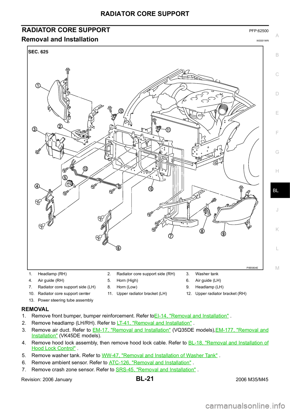
1. Headlamp (RH) 2. Radiator core support side (RH) 3. Washer tank
4. Air guide (RH) 5. Horn (High) 6. Air guide (LH)
7. Radiator core support side (LH) 8. Horn (Low) 9. Headlamp (LH)
10. Radiator core support center 11. Upper radiator bracket (LH) 12. Upper radiator bracket (RH)
13. Power steering tube assembly
PIIB5804E
Page 961 of 5621

BL-22
RADIATOR CORE SUPPORT
Revision: 2006 January2006 M35/M45
8. Remove air guide (LH/RH).
9. Remove power steering tube assembly. Refer to PS-43, "
Removal and Installation" .
10. Remove horn (High/Low). Refer to WW-54, "
Removal and Installation" .
11. Remove mounting harness clip on radiator core support assembly, the harness is separate.
12. Remove ICC sensor integrated unit. Refer to ACS-69, "
ICC Sensor Integrated Unit" .
13. Remove upper radiator bracket (LH/RH) with power tool.
14. Remove radiator core support side with power tool.
15. Remove radiator core support side (LH/RH) with power tool.
16. Remove radiator core support center.
CAUTION:
Put a wooden block under the radiator assembly to prevent
the radiator assembly from falling.
INSTALLATION
Install in the reverse order of removal.
PIIB3891J
PIIB3892J
PIIB3890J
Page 987 of 5621
BL-48
INTELLIGENT KEY SYSTEM
Revision: 2006 January2006 M35/M45
System DescriptionNIS001X8
The Intelligent Key system is a system that makes it possible to lock and unlock the door locks (door lock/
unlock function), open the trunk (trunk open function), and start the engine (engine start function) by carry-
ing around the Intelligent Key (without some key operation), which operates based on the results of elec-
tronic ID verification using two-way communications between the Intelligent Key and the vehicle
(Intelligent Key unit).
CAUTION:
The driver should always carry the Intelligent Key
Operation of the remote controller buttons on the Intelligent Key also provides the same functions as the
remote controller entry system. (Remote keyless entry functions)
If an action that does not meet the operating conditions of the Intelligent Key system is taken, the buzzer
goes off to inform the driver. (Warning chime functions)
When a door lock is locked, unlocked or trunk open with request switch or remote controller button opera-
tion, the hazard lamps flash and the Intelligent Key warning buzzer or horn sounds (Hazard and buzzer/
horn reminder function).
Even if the Intelligent Key battery is completely discharged, the door locks can be locked and unlocked
with the mechanical key built into the Intelligent Key, and then initiates engine by inserting Intelligent Key
into key slot.
The settings for each function can be changed with the CONSULT-II.
If an Intelligent Key is lost, a new Intelligent Key can be registered. A maximum of 4 Intelligent Keys can
be registered.
It has been made possible to diagnose the system and register an Intelligent Key with the CONSULT-II.
DOOR LOCK/UNLOCK/TRUNK OPEN FUNCTION
Only when pressing the request switch, it is possible to lock and unlock the door and open the trunk by carry-
ing around the Intelligent Key (without some key operation).
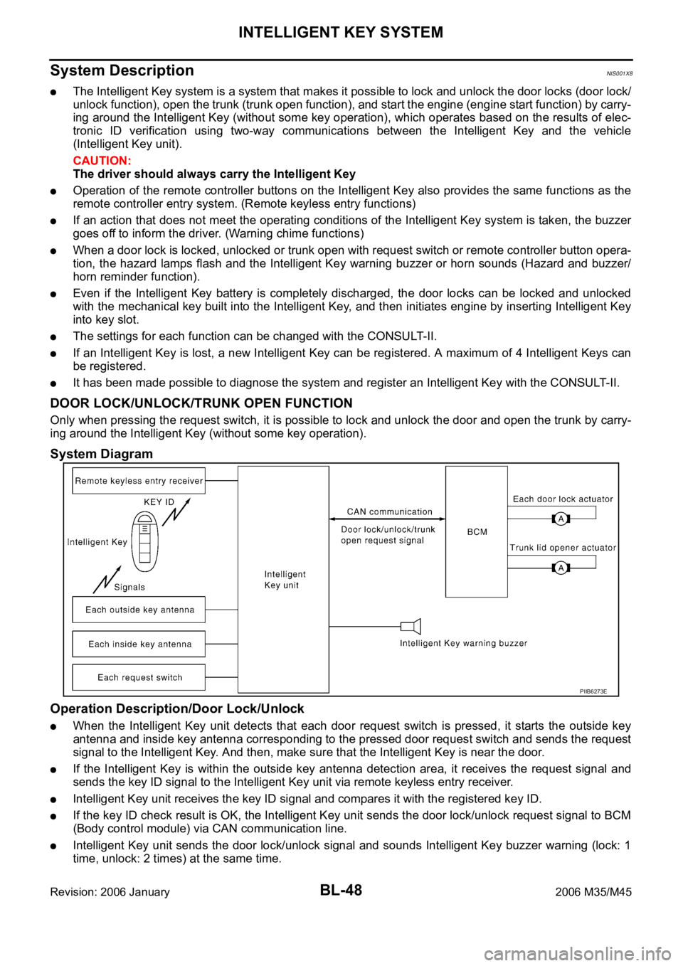
System Diagram
Operation Description/Door Lock/Unlock
When the Intelligent Key unit detects that each door request switch is pressed, it starts the outside key
antenna and inside key antenna corresponding to the pressed door request switch and sends the request
signal to the Intelligent Key. And then, make sure that the Intelligent Key is near the door.
If the Intelligent Key is within the outside key antenna detection area, it receives the request signal and
sends the key ID signal to the Intelligent Key unit via remote keyless entry receiver.
Intelligent Key unit receives the key ID signal and compares it with the registered key ID.
If the key ID check result is OK, the Intelligent Key unit sends the door lock/unlock request signal to BCM
(Body control module) via CAN communication line.
Intelligent Key unit sends the door lock/unlock signal and sounds Intelligent Key buzzer warning (lock: 1
time, unlock: 2 times) at the same time.
PIIB6273E
Page 991 of 5621
BL-52
INTELLIGENT KEY SYSTEM
Revision: 2006 January2006 M35/M45
REMOTE KEYLESS ENTRY FUNCTIONS
The Intelligent Key has the same functions as the remote control entry system. Therefore, it can be used in the
same manner as the remote controller by operating the door lock/unlock button and trunk open button.
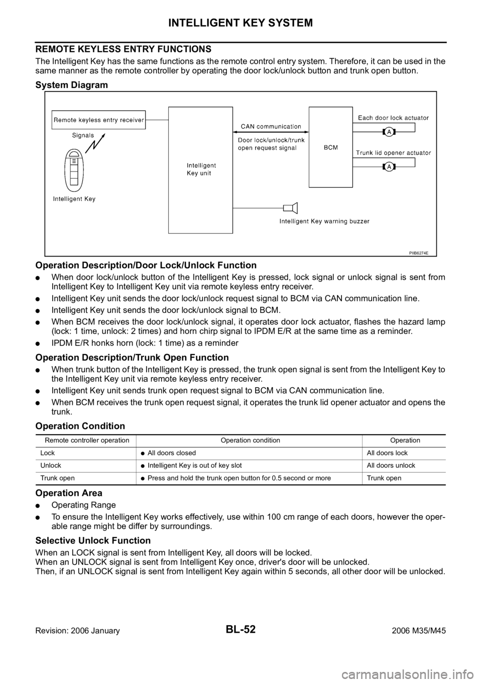
System Diagram
Operation Description/Door Lock/Unlock Function
When door lock/unlock button of the Intelligent Key is pressed, lock signal or unlock signal is sent from
Intelligent Key to Intelligent Key unit via remote keyless entry receiver.
Intelligent Key unit sends the door lock/unlock request signal to BCM via CAN communication line.
Intelligent Key unit sends the door lock/unlock signal to BCM.
When BCM receives the door lock/unlock signal, it operates door lock actuator, flashes the hazard lamp
(lock: 1 time, unlock: 2 times) and horn chirp signal to IPDM E/R at the same time as a reminder.
IPDM E/R honks horn (lock: 1 time) as a reminder
Operation Description/Trunk Open Function
When trunk button of the Intelligent Key is pressed, the trunk open signal is sent from the Intelligent Key to
the Intelligent Key unit via remote keyless entry receiver.
Intelligent Key unit sends trunk open request signal to BCM via CAN communication line.
When BCM receives the trunk open request signal, it operates the trunk lid opener actuator and opens the
trunk.
Operation Condition
Operation Area
Operating Range
To ensure the Intelligent Key works effectively, use within 100 cm range of each doors, however the oper-
able range might be differ by surroundings.
Selective Unlock Function
When an LOCK signal is sent from Intelligent Key, all doors will be locked.
When an UNLOCK signal is sent from Intelligent Key once, driver's door will be unlocked.
Then, if an UNLOCK signal is sent from Intelligent Key again within 5 seconds, all other door will be unlocked.
PIIB6274E
Remote controller operation Operation condition Operation
Lock
All doors closed All doors lock
Unlock
Intelligent Key is out of key slot All doors unlock
Trunk open
Press and hold the trunk open button for 0.5 second or more Trunk open
Page 992 of 5621
INTELLIGENT KEY SYSTEM
BL-53
C
D
E
F
G
H
J
K
L
MA
B
BL
Revision: 2006 January2006 M35/M45
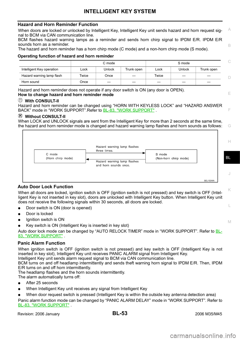
Hazard and Horn Reminder Function
When doors are locked or unlocked by Intelligent Key, Intelligent Key unit sends hazard and horn request sig-
nal to BCM via CAN communication line.
BCM flashes hazard warning lamps as a reminder and sends horn chirp signal to IPDM E/R. IPDM E/R
sounds horn as a reminder.
The hazard and horn reminder has a horn chirp mode (C mode) and a non-horn chirp mode (S mode).
Operating function of hazard and horn reminder
Hazard and horn reminder does not operate if any door switch is ON (any door is OPEN).
How to change hazard and horn reminder mode
With CONSULT-II
Hazard and horn reminder can be changed using “HORN WITH KEYLESS LOCK” and “HAZARD ANSWER
BACK” mode in “WORK SUPPORT”.Refer to BL-83, "
WORK SUPPORT" .
Without CONSULT-II
When LOCK and UNLOCK signals are sent from the Intelligent Key for more than 2 seconds at the same time,
the hazard and horn reminder mode is changed and hazard warning lamp flashes and horn sounds as follows:
Auto Door Lock Function
When all doors are locked, ignition switch is OFF (ignition switch is not pressed) and key switch is OFF (Intel-
ligent Key is not inserted in key slot), doors are unlocked with Intelligent Key button. When Intelligent Key unit
does not receive the following signals within 30 seconds, all doors are locked.
Door switch is ON (door is opened)
Door is locked
Ignition switch is ON
Key switch is ON (Intelligent Key is inserted in key slot)
Auto door lock mode can be changed by “AUTO RELOCK TIMER” mode in “WORK SUPPORT”. Refer to BL-
83, "WORK SUPPORT" .
Panic Alarm Function
When ignition switch is OFF (ignition switch is not pressed) and key switch is OFF (Intelligent Key is not
inserted in key slot), Intelligent Key unit receives PANIC ALARM signal from Intelligent Key.
Intelligent Key unit sends alarm request signal to BCM via CAN communication line.
BCM turns on and off headlamp intermittently and sends theft warning horn signal to IPDM E/R. Then, IPDM
E/R turns on and off horn intermittently.
The headlamp flashes and the horn sounds intermittently.
The alarm automatically turns off:
After 25 seconds
When Intelligent Key unit receives any signal from Intelligent Key
When door request switch is pressed (Intelligent Key is within the outside key antenna detection area)
Panic alarm function mode can be changed by “PANIC ALARM DELAY” mode in “WORK SUPPORT”. Refer to
BL-83, "
WORK SUPPORT" .
C mode S mode
Intelligent Key operation Lock Unlock Trunk open Lock Unlock Trunk open
Hazard warning lamp flash Twice Once — Twice — —
Horn sound Once—————
SEL153WA
Page 993 of 5621

BL-54
INTELLIGENT KEY SYSTEM
Revision: 2006 January2006 M35/M45
Keyless Power Window Down (Open) Function
All power windows open when the unlock button on Intelligent Key is activated and kept pressed for more than
3 seconds with the ignition switch OFF. The windows keep opening if the unlock button is continuously
pressed.
The power window opening stops when the following operations are performed:
When the unlock button is kept pressed more than 15 seconds.
When the ignition switch is turned ON while the power window opening is operated.
When the unlock button is released.
While retained power operation activate, Keyless power window down (open) Function cannot be operated.
Keyless power window down operation mode can be changed by “P/W DOWN DELAY” mode in “WORK SUP-
PORT”. Refer to BL-83, "
WORK SUPPORT" .
Room Lamp Illumination Operation
When the following conditions are met:
Condition of interior lamp switch is in DOOR position
Door switch OFF (all the doors are closed)
Intelligent Key system turns on interior lamp (for 30 seconds) by receiving UNLOCK signal from Intelligent
Key. For detailed description, refer to LT- 2 7 0 , "
ROOM LAMP TIMER OPERATION" .
List of Operation Related Parts
Parts marked with are the parts related to operation.
ENGINE START FUNCTION
Refer to BL-127, "INTELLIGENT KEY SYSTEM/ENGINE START FUNCTION" .
Remote keyless entry functions
Intelligent Key
Key slot
Door request switch (Driver, Passenger)
Door switch
Trunk room lamp switch
Door lock actuator
Trunk lid opener actuator
Intelligent Key warning buzzer
Intelligent Key unit
CAN communication system
BCM
Combination meter
Hazard warning lamp
Horn
IPDM E/R
Head lamp
Door lock/unlock function by remote control button
Trunk open function by remote control button
Hazard and horn reminder function
Selective unlock function
Keyless power window down (open) function
Auto door lock function
Panic alarm function
Page 1016 of 5621

INTELLIGENT KEY SYSTEM
BL-77
C
D
E
F
G
H
J
K
L
MA
B
BL
Revision: 2006 January2006 M35/M45
Terminals and Reference Value for BCMNIS001XE
*1: In the state that hazard reminder operates.
*2: In the state that room lamp switch is in “DOOR” position.
Terminals and Reference Value for IPDM E/RNIS001XF
Te r m i -
nalWire
ColorItem ConditionVoltage (V)
Approx.
11 V Ignition switch (ACC) Ignition switch is in ACC or ON position Battery voltage
12 PFront door switch passenger
sideDoor open (ON)
Close (OFF) 0 8
13 O/L Rear door switch RH Door open (ON)
Close (OFF) 0 Battery voltage
37 LG Key switch signalInsert Intelligent Key into key slot. Battery voltage
Remove Intelligent Key from key slot. 0
38 W Ignition switch (ON)Ignition switch is in ON or START posi-
tion.Battery voltage
39 L CAN-H — —
40 P CAN-L — —
42 P Power supply (fuse) — Battery voltage
52 B Ground — 0
55 W Power supply (Fusible link) — Battery voltage
57 SB Trunk room lamp switch Trunk lid open (ON)
Close (OFF) 0 Battery voltage
62 V Front door switch driver side Door open (ON)
Close (OFF) 0 Battery voltage
63 R/G Rear door switch LH Door open (ON)
Close (OFF) 0 Battery voltage
Te r m i n a l Wire
ColorItem ConditionVoltage (V)
Approx.
48 G/B Horn relay Press panic alarm bottom.Horn sounds. 0
Horn does not sound. Battery voltage
49 L CAN-H — —
50 P CAN-L — —