lock INFINITI M35 2006 Factory Service Manual
[x] Cancel search | Manufacturer: INFINITI, Model Year: 2006, Model line: M35, Model: INFINITI M35 2006Pages: 5621, PDF Size: 65.56 MB
Page 5067 of 5621

RFD-24
REAR FINAL DRIVE ASSEMBLY
Revision: 2006 January2006 M35/M45
10. For proper reinstallation, paint matching marks on one differen-
tial case assembly.
CAUTION:
For matching marks, use paint. Do not damage differential
case and drive gear.
11. Remove drive gear mounting bolts.
12. Tap drive gear off differential case assembly with a soft hammer.
CAUTION:
Tap evenly all around to keep drive gear from bending.
13. Remove lock pin of pinion mate shaft with a punch from drive
gear side.
14. Remove pinion mate shaft.
15. Turn pinion mate gear, then remove pinion mate gear, pinion
mate thrust washer, side gear and side gear thrust washer from
differential case.
Drive Pinion Assembly
1. Remove differential assembly. Refer to RFD-22, "Differential Assembly" .
PDIA0496E
PDIA0759J
SDIA0031J
SDIA0032J
Page 5068 of 5621
REAR FINAL DRIVE ASSEMBLY
RFD-25
C
E
F
G
H
I
J
K
L
MA
B
RFD
Revision: 2006 January2006 M35/M45
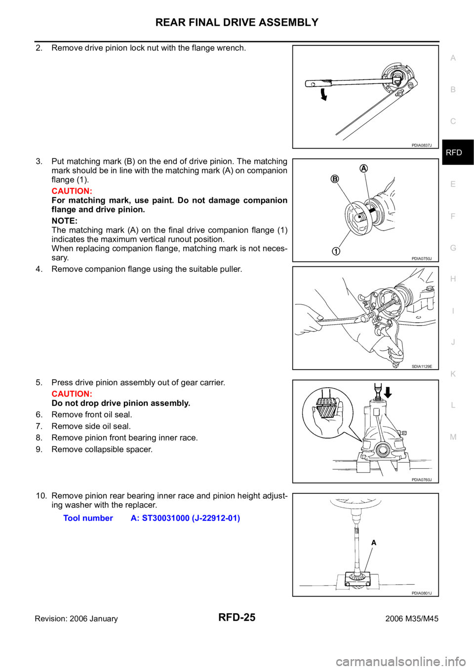
2. Remove drive pinion lock nut with the flange wrench.
3. Put matching mark (B) on the end of drive pinion. The matching
mark should be in line with the matching mark (A) on companion
flange (1).
CAUTION:
For matching mark, use paint. Do not damage companion
flange and drive pinion.
NOTE:
The matching mark (A) on the final drive companion flange (1)
indicates the maximum vertical runout position.
When replacing companion flange, matching mark is not neces-
sary.
4. Remove companion flange using the suitable puller.
5. Press drive pinion assembly out of gear carrier.
CAUTION:
Do not drop drive pinion assembly.
6. Remove front oil seal.
7. Remove side oil seal.
8. Remove pinion front bearing inner race.
9. Remove collapsible spacer.
10. Remove pinion rear bearing inner race and pinion height adjust-
ing washer with the replacer.
PDIA0837J
PDIA0750J
SDIA1129E
PDIA0760J
Tool number A: ST30031000 (J-22912-01)
PDIA0801J
Page 5072 of 5621
REAR FINAL DRIVE ASSEMBLY
RFD-29
C
E
F
G
H
I
J
K
L
MA
B
RFD
Revision: 2006 January2006 M35/M45
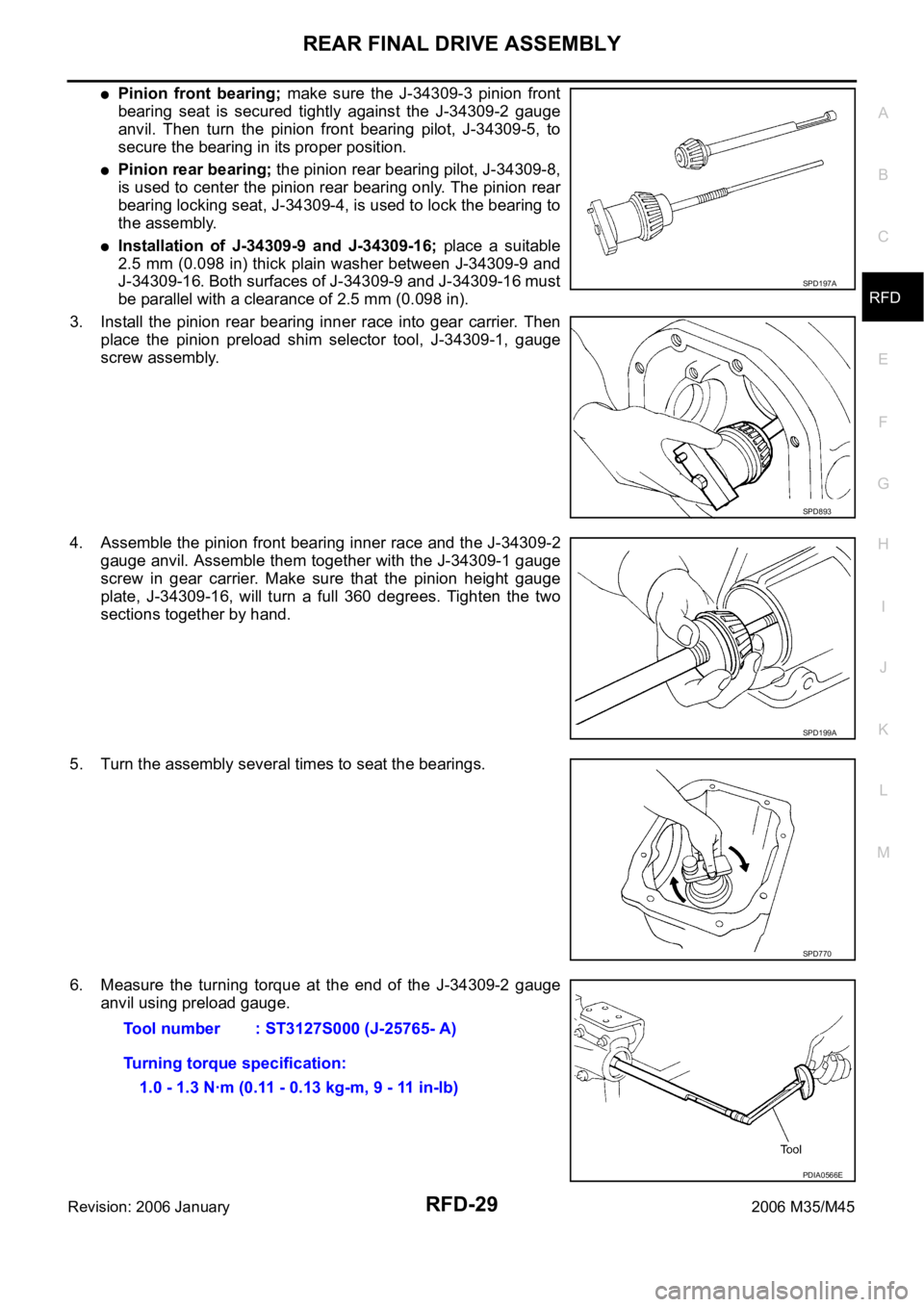
Pinion front bearing; make sure the J-34309-3 pinion front
bearing seat is secured tightly against the J-34309-2 gauge
anvil. Then turn the pinion front bearing pilot, J-34309-5, to
secure the bearing in its proper position.
Pinion rear bearing; the pinion rear bearing pilot, J-34309-8,
is used to center the pinion rear bearing only. The pinion rear
bearing locking seat, J-34309-4, is used to lock the bearing to
the assembly.
Installation of J-34309-9 and J-34309-16; place a suitable
2.5 mm (0.098 in) thick plain washer between J-34309-9 and
J-34309-16. Both surfaces of J-34309-9 and J-34309-16 must
be parallel with a clearance of 2.5 mm (0.098 in).
3. Install the pinion rear bearing inner race into gear carrier. Then
place the pinion preload shim selector tool, J-34309-1, gauge
screw assembly.
4. Assemble the pinion front bearing inner race and the J-34309-2
gauge anvil. Assemble them together with the J-34309-1 gauge
screw in gear carrier. Make sure that the pinion height gauge
plate, J-34309-16, will turn a full 360 degrees. Tighten the two
sections together by hand.
5. Turn the assembly several times to seat the bearings.
6. Measure the turning torque at the end of the J-34309-2 gauge
anvil using preload gauge.
SPD197A
SPD893
SPD199A
SPD770
Tool number : ST3127S000 (J-25765- A)
Turning torque specification:
1.0 - 1.3 Nꞏm (0.11 - 0.13 kg-m, 9 - 11 in-lb)
PDIA0566E
Page 5076 of 5621
REAR FINAL DRIVE ASSEMBLY
RFD-33
C
E
F
G
H
I
J
K
L
MA
B
RFD
Revision: 2006 January2006 M35/M45
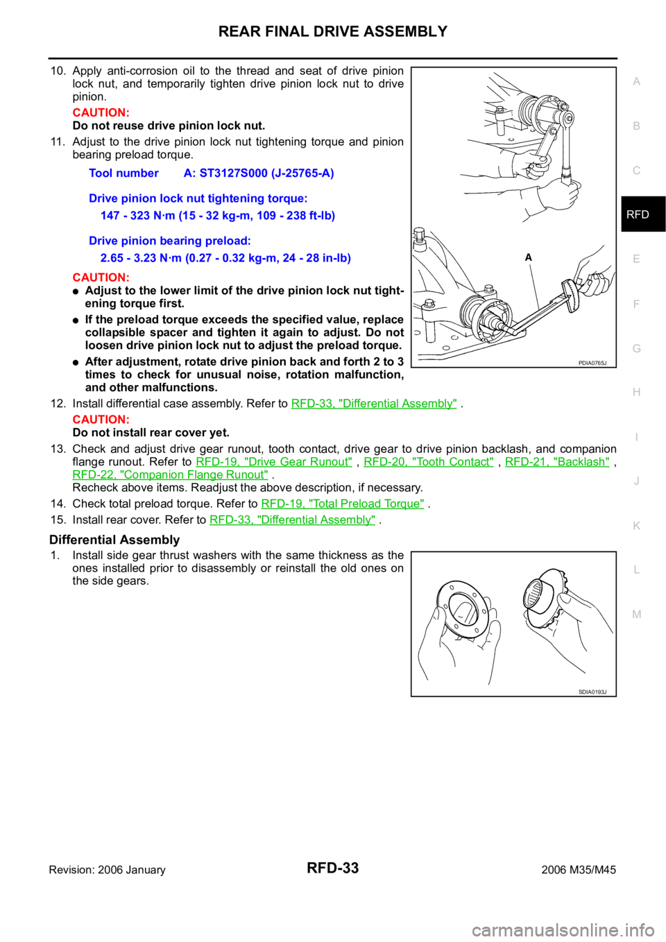
10. Apply anti-corrosion oil to the thread and seat of drive pinion
lock nut, and temporarily tighten drive pinion lock nut to drive
pinion.
CAUTION:
Do not reuse drive pinion lock nut.
11. Adjust to the drive pinion lock nut tightening torque and pinion
bearing preload torque.
CAUTION:
Adjust to the lower limit of the drive pinion lock nut tight-
ening torque first.
If the preload torque exceeds the specified value, replace
collapsible spacer and tighten it again to adjust. Do not
loosen drive pinion lock nut to adjust the preload torque.
After adjustment, rotate drive pinion back and forth 2 to 3
times to check for unusual noise, rotation malfunction,
and other malfunctions.
12. Install differential case assembly. Refer to RFD-33, "
Differential Assembly" .
CAUTION:
Do not install rear cover yet.
13. Check and adjust drive gear runout, tooth contact, drive gear to drive pinion backlash, and companion
flange runout. Refer to RFD-19, "
Drive Gear Runout" , RFD-20, "Tooth Contact" , RFD-21, "Backlash" ,
RFD-22, "
Companion Flange Runout" .
Recheck above items. Readjust the above description, if necessary.
14. Check total preload torque. Refer to RFD-19, "
Total Preload Torque" .
15. Install rear cover. Refer to RFD-33, "
Differential Assembly" .
Differential Assembly
1. Install side gear thrust washers with the same thickness as the
ones installed prior to disassembly or reinstall the old ones on
the side gears.Tool number A: ST3127S000 (J-25765-A)
Drive pinion lock nut tightening torque:
147 - 323 Nꞏm (15 - 32 kg-m, 109 - 238 ft-lb)
Drive pinion bearing preload:
2.65 - 3.23 Nꞏm (0.27 - 0.32 kg-m, 24 - 28 in-lb)
PDIA0765J
SDIA0193J
Page 5077 of 5621

RFD-34
REAR FINAL DRIVE ASSEMBLY
Revision: 2006 January2006 M35/M45
2. Install side gears and thrust washers into differential case.
CAUTION:
Make sure that the circular clip is installed to side gears.
3. Align 2 pinion mate gears in diagonally opposite positions, then
rotate and install them into differential case after installing thrust
washer to pinion mate gear.
4. Align the lock pin holes on differential case with shaft, and install
pinion mate shaft.
5. Measure side gear end play. If necessary, select the appropriate
side gear thrust washers. Refer to RFD-26, "
Differential Side
Gear Clearance" .
6. Drive a lock pin into pinion mate shaft, using a punch.
Make sure lock pin is flush with differential case.
CAUTION:
Do not reuse lock pin.
7. Align the matching mark of differential case with the mark of
drive gear, then place drive gear.
8. Apply thread locking sealant into the thread hole of drive gear.
Use Genuine High Strength Thread Locking Sealant or
equivalent. Refer to GI-48, "
RECOMMENDED CHEMICAL
PRODUCTS AND SEALANTS" .
CAUTION:
Drive gear back and threaded holes shall be cleaned and
degreased sufficiently.
SDIA2025E
SDIA0195J
SPD030
SDIA2593E
SDIA2594E
Page 5083 of 5621

RSU-2
PRECAUTIONS
Revision: 2006 January2006 M35/M45
PRECAUTIONSPFP:00001
PrecautionsNES000J2
When installing rubber bushings, final tightening must be carried out under unladen conditions with tires
on ground. Oil will shorten the life of rubber bushings. Be sure to wipe off any spilled oil.
–Unladen conditions mean that fuel, engine coolant and lubricant are full. Spare tire, jack, hand tools and
mats are in designated positions.
After servicing suspension parts, be sure to check wheel alignment.
Self-lock nuts are not reusable. Always use new ones when installing. Since new self-lock nuts are pre-
oiled, tighten as they are.
Page 5091 of 5621
RSU-10
SHOCK ABSORBER
Revision: 2006 January2006 M35/M45
SHOCK ABSORBERPFP:56210
Removal and InstallationNES000JA
REMOVAL
1. Remove tires from vehicle with a power tool.
2. Set a jack under rear lower link to relieve the coil spring tension.
3. Remove shock absorber lower end bolt with a power tool.
4. Gradually lower the jack to remove it from rear lower link.
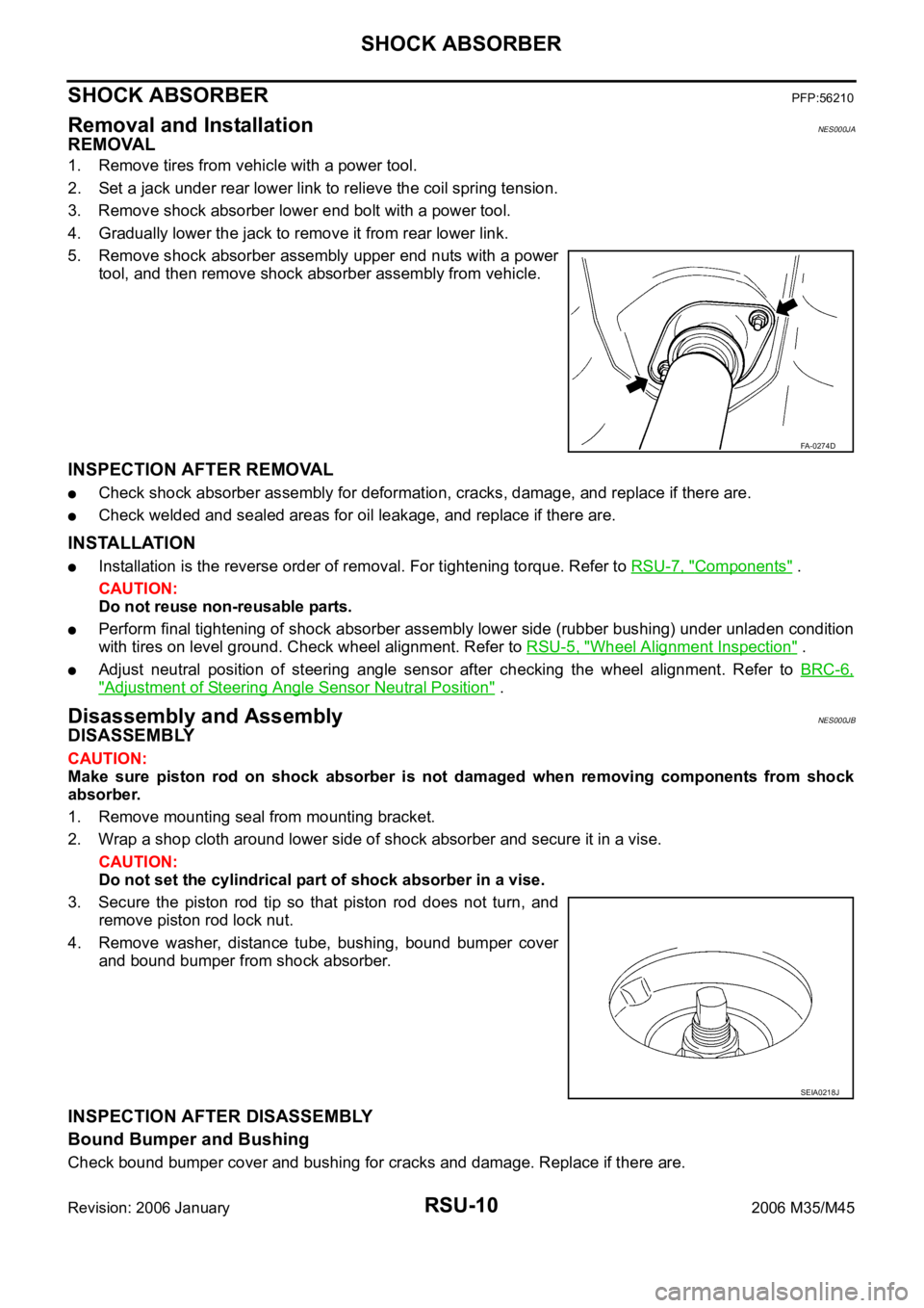
5. Remove shock absorber assembly upper end nuts with a power
tool, and then remove shock absorber assembly from vehicle.
INSPECTION AFTER REMOVAL
Check shock absorber assembly for deformation, cracks, damage, and replace if there are.
Check welded and sealed areas for oil leakage, and replace if there are.
INSTALLATION
Installation is the reverse order of removal. For tightening torque. Refer to RSU-7, "Components" .
CAUTION:
Do not reuse non-reusable parts.
Perform final tightening of shock absorber assembly lower side (rubber bushing) under unladen condition
with tires on level ground. Check wheel alignment. Refer to RSU-5, "
Wheel Alignment Inspection" .
Adjust neutral position of steering angle sensor after checking the wheel alignment. Refer to BRC-6,
"Adjustment of Steering Angle Sensor Neutral Position" .
Disassembly and AssemblyNES000JB
DISASSEMBLY
CAUTION:
Make sure piston rod on shock absorber is not damaged when removing components from shock
absorber.
1. Remove mounting seal from mounting bracket.
2. Wrap a shop cloth around lower side of shock absorber and secure it in a vise.
CAUTION:
Do not set the cylindrical part of shock absorber in a vise.
3. Secure the piston rod tip so that piston rod does not turn, and
remove piston rod lock nut.
4. Remove washer, distance tube, bushing, bound bumper cover
and bound bumper from shock absorber.
INSPECTION AFTER DISASSEMBLY
Bound Bumper and Bushing
Check bound bumper cover and bushing for cracks and damage. Replace if there are.
FA-0274D
SEIA0218J
Page 5102 of 5621

PRE-CRASH SEAT BELT
SB-3
C
D
E
F
G
I
J
K
L
MA
B
SB
Revision: 2006 January2006 M35/M45
PRE-CRASH SEAT BELTPFP:98845
Component Parts and Harness Connector LocationNHS0007X
System DescriptionNHS0007Y
Pre-crash seat belt system is adapted to front seat belts RH/LH.
When the pre-crash seat belt control unit judges the emergency braking operation, it gives the sense of
security by the motor built into the pre-crash seat belt retracting the shoulder belt and suppressing the
crew's posture change. Also, it eases the damage of the collision.
PHIA1123E
1. Fuse block (J/B) 2.Fuse, fusible link and relay block
(J/B)3.Pre-crash seat belt control unit B142
(View with the trunk side finisher LH
removed)
4.Brake pedal stroke sensor E125
(View with the instrument driver
lower panel removed)5.Pre-crash seat belt motor B32 (LH),
B8 (RH)
(View with the center pillar lower
garnish removed)6.Seat belt buckle switch B203 (driver
seat) B253 (passenger seat)
Page 5116 of 5621
![INFINITI M35 2006 Factory Service Manual PRE-CRASH SEAT BELT
SB-17
C
D
E
F
G
I
J
K
L
MA
B
SB
Revision: 2006 January2006 M35/M45
Ignition Power Supply Circuit CheckNHS00089
1. CHECK FUSE
Check 10A fuse [No.15, located in fuse block (J/B)].
NO INFINITI M35 2006 Factory Service Manual PRE-CRASH SEAT BELT
SB-17
C
D
E
F
G
I
J
K
L
MA
B
SB
Revision: 2006 January2006 M35/M45
Ignition Power Supply Circuit CheckNHS00089
1. CHECK FUSE
Check 10A fuse [No.15, located in fuse block (J/B)].
NO](/img/42/57023/w960_57023-5115.png)
PRE-CRASH SEAT BELT
SB-17
C
D
E
F
G
I
J
K
L
MA
B
SB
Revision: 2006 January2006 M35/M45
Ignition Power Supply Circuit CheckNHS00089
1. CHECK FUSE
Check 10A fuse [No.15, located in fuse block (J/B)].
NOTE:
Refer to SB-3, "
Component Parts and Harness Connector Location" .
OK or NG
OK >> GO TO 2.
NG >> If fuse is blown out, be sure to eliminate cause of malfunction before installing new fuse. Refer to
PG-3, "
POWER SUPPLY ROUTING CIRCUIT" .
2. CHECK IGNITION POWER SUPPLY CIRCUIT
1. Disconnect pre-crash seat belt control unit connector.
2. Turn ignition switch ON.
3. Check voltage between pre-crash seat belt control unit harness
connector and ground.
OK or NG
OK >> Ignition power supply circuit is OK.
NG >> Check pre-crash seat belt control unit ignition power supply circuit harness.
Motor Power Supply and Ground Circuit Check [B2454]NHS0008A
1. CHECK FUSE
Check 30A fusible link (letter G , located in the fuse and fusible link box).
NOTE:
Refer to SB-3, "
Component Parts and Harness Connector Location" .
OK or NG
OK >> GO TO 2.
NG >> If fuse is blown out, be sure to eliminate cause of malfunction before installing new fuse. Refer to
PG-3, "
POWER SUPPLY ROUTING CIRCUIT" .
Terminal
Voltage (V)
(Approx.) (+)
(–) Pre-crash seat
belt control unit
connectorTerminal
B142 13 Ground Battery voltage
PHIA1126E
Page 5130 of 5621
SEAT BELTS
SB-31
C
D
E
F
G
I
J
K
L
MA
B
SB
Revision: 2006 January2006 M35/M45
2. Remove the shoulder anchor.
Remove the center pillar lower and upper garnishes, refer to EI-37, "BODY SIDE TRIM" .
Remove the fixing anchor nut of the shoulder anchor.
3. Remove the seat bert assembly.
Disconnect the seat belt pre-tensioner connector.
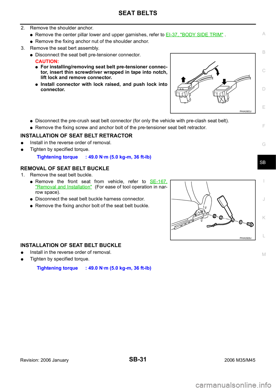
CAUTION:
For installing/removing seat belt pre-tensioner connec-
tor, insert thin screwdriver wrapped in tape into notch,
lift lock and remove connector.
Install connector with lock raised, and push lock into
connector.
Disconnect the pre-crush seat belt connector (for only the vehicle with pre-clash seat belt).
Remove the fixing screw and anchor bolt of the pre-tensioner seat belt retractor.
INSTALLATION OF SEAT BELT RETRACTOR
Install in the reverse order of removal.
Tighten by specified torque.
REMOVAL OF SEAT BELT BUCKLE
1. Remove the seat belt buckle.
Remove the front seat from vehicle, refer to SE-167,
"Removal and Installation" (For ease of tool operation in nar-
row space).
Disconnect the seat belt buckle harness connector.
Remove the fixing anchor bolt of the seat belt buckle.
INSTALLATION OF SEAT BELT BUCKLE
Install in the reverse order of removal.
Tighten by specified torque.
PHIA0953J
Tightening torque : 49.0 Nꞏm (5.0 kg-m, 36 ft-lb)
PHIA0926J
Tightening torque : 49.0 Nꞏm (5.0 kg-m, 36 ft-lb)