Panel INFINITI M35 2006 Factory Service Manual
[x] Cancel search | Manufacturer: INFINITI, Model Year: 2006, Model line: M35, Model: INFINITI M35 2006Pages: 5621, PDF Size: 65.56 MB
Page 1 of 5621

A
B
C
D
E
F
G
H
I
J
K
M
L
QUICK REFERENCE INDEX
AGENERAL INFORMATIONGIGeneral Information
BENGINEEMEngine Mechanical
LUEngine Lubrication System
COEngine Cooling System
ECEngine Control System
FLFuel System
EXExhaust System
ACCAccelerator Control System
CTRANSMISSION/
TRANSAXLEATAutomatic Transmission
DDRIVELINE/AXLETFTransfer
PRPropeller Shaft
FFDFront Final Drive
RFDRear Final Drive
FAXFront Axle
RAXRear Axle
ESUSPENSIONFSUFront Suspension
RSURear Suspension
WTRoad Wheels & Tires
FBRAKESBRBrake System
PBParking Brake System
BRCBrake Control System
GSTEERINGPSPower Steering System
STCSteering Control System
HRESTRAINTSSBSeat Belts
SRSSupplemental Restraint System
(SRS)
IBODYBLBody, Lock & Security System
GWGlasses, Window System & Mir-
rors
RFRoof
EIExterior & Interior
IPInstrument Panel
SESeat
JAIR CONDITIONERATCAutomatic Air Conditioner
KELECTRICALSCStarting & Charging System
LTLighting System
DIDriver Information System
WWWiper, Washer & Horn
BCSBody Control System
LANLAN System
AVAudio-Visual System
ACSAuto Cruise Control System
PGPower Supply, Ground & Circuit Ele-
ments
LMAINTENANCEMAMaintenance
MINDEXIDXAlphabetical Index
Edition: January 2005
Revision: January 2006
Page 119 of 5621
 SYSTEM
Revision: 2006 January2006 M35/M45
ON BOARD DIAGNOSTIC (OBD) SYSTEMPFP:00028
IntroductionNCS001JX
The A/T system has two self-diagnostic systems.
The first is")
AT-40
ON BOARD DIAGNOSTIC (OBD) SYSTEM
Revision: 2006 January2006 M35/M45
ON BOARD DIAGNOSTIC (OBD) SYSTEMPFP:00028
IntroductionNCS001JX
The A/T system has two self-diagnostic systems.
The first is the emission-related on board diagnostic system (OBD-II) performed by the TCM in combination
with the ECM. The malfunction is indicated by the MIL (malfunction indicator lamp) and is stored as a DTC in
the ECM memory but not the TCM memory.
The second is the TCM original self-diagnosis indicated by the A/T CHECK indicator lamp. The malfunction is
stored in the TCM memory. The detected items are overlapped with OBD-II self-diagnostic items. For detail,
refer to AT- 9 2 , "
Display Items List" .
OBD-II Function for A/T SystemNCS001JY
The ECM provides emission-related on board diagnostic (OBD-II) functions for the A/T system. One function
is to receive a signal from the TCM used with OBD-related parts of the A/T system. The signal is sent to the
ECM when a malfunction occurs in the corresponding OBD-related part. The other function is to indicate a
diagnostic result by means of the MIL (malfunction indicator lamp) on the instrument panel. Sensors, switches
and solenoid valves are used as sensing elements.
The MIL automatically illuminates in “One or Two Trip Detection Logic” when a malfunction is sensed in rela-
tion to A/T system parts.
One or Two Trip Detection Logic of OBD-IINCS001JZ
ONE TRIP DETECTION LOGIC
If a malfunction is sensed during the first test drive, the MIL will illuminate and the malfunction will be stored in
the ECM memory as a DTC. The TCM is not provided with such a memory function.
TWO TRIP DETECTION LOGIC
When a malfunction is sensed during the first test drive, it is stored in the ECM memory as a 1st trip DTC
(diagnostic trouble code) or 1st trip freeze frame data. At this point, the MIL will not illuminate. — 1st trip
If the same malfunction as that experienced during the first test drive is sensed during the second test drive,
the MIL will illuminate. — 2nd trip
The “Trip” in the “One or Two Trip Detection Logic” means a driving mode in which self-diagnosis is performed
during vehicle operation.
OBD-II Diagnostic Trouble Code (DTC)NCS001K0
HOW TO READ DTC AND 1ST TRIP DTC
DTC and 1st trip DTC can be read by the following methods.
( with CONSULT-II or GST) CONSULT-II or GST (Generic Scan Tool) Examples: P0705, P0720 etc.
These DTC are prescribed by SAE J2012.
(CONSULT-II also displays the malfunctioning component or system.)
1st trip DTC No. is the same as DTC No.
Output of the diagnostic trouble code indicates that the indicated circuit has a malfunction. How-
ever, in case of the Mode II and GST, they do not indicate whether the malfunction is still occurring
or occurred in the past and returned to normal.
CONSULT-II can identify them as shown below, therefore, CONSULT-II (if available) is recom-
mended.
A sample of CONSULT-II display for DTC and 1st trip DTC is shown
on the next page. DTC or 1st trip DTC of a malfunction is displayed
in SELF-DIAGNOSTIC RESULTS mode for “ENGINE” with CON-
SULT-II. Time data indicates how many times the vehicle was driven
after the last detection of a DTC.
BCIA0030E
Page 122 of 5621
 SYSTEM
AT-43
D
E
F
G
H
I
J
K
L
MA
B
AT
Revision: 2006 January2006 M35/M45
HOW TO ERASE DTC (WITH GST)
1. If the ignition switch stays ON after repair work, be sure to turn i")
ON BOARD DIAGNOSTIC (OBD) SYSTEM
AT-43
D
E
F
G
H
I
J
K
L
MA
B
AT
Revision: 2006 January2006 M35/M45
HOW TO ERASE DTC (WITH GST)
1. If the ignition switch stays ON after repair work, be sure to turn ignition switch OFF once. Wait at least 10
seconds and then turn it ON (engine stopped) again.
2. Perform AT-103, "
OBD-II SELF-DIAGNOSTIC PROCEDURE (WITH GST)" . (The engine warm-up step
can be skipped when performing the diagnosis only to erase the DTC.)
3. Select Mode 4 with GST (Generic Scan Tool). For details, refer to EC-146, "
Generic Scan Tool (GST)
Function" (for VQ35DE engine), EC-859, "Generic Scan Tool (GST) Function" (for VK45DE engine).
HOW TO ERASE DTC (NO TOOLS)
The A/T CHECK indicator lamp is located on the instrument panel.
1. If the ignition switch stays ON after repair work, be sure to turn ignition switch OFF once. Wait at least 10
seconds and then turn it ON (engine stopped) again.
2. Perform AT-103, "
TCM SELF-DIAGNOSTIC PROCEDURE (NO TOOLS)" . (The engine warm-up step
can be skipped when performing the diagnosis only to erase the DTC.)
3. Perform “OBD-II SELF-DIAGNOSTIC PROCEDURE (No tools)”. Refer to EC-67, "
How to Erase DTC"
(for VQ35DE engine), EC-778, "How to Erase DTC" (for VK45DE engine).
Malfunction Indicator Lamp (MIL)NCS001K1
DESCRIPTION
The MIL is located on the combination meters.
1. The MIL will light up when the ignition switch is turned ON with-
out the engine running. This is a bulb check.
If the MIL does not light up, refer to DI-40, "WARNING LAMPS" ,
or see EC-722, "
MIL AND DATA LINK CONNECTOR" (for
VQ35DE engine), EC-1459, "
MIL AND DATA LINK CONNEC-
TOR" (for VK45DE engine).
2. When the engine is started, the MIL should go off.
If the MIL remains on, the on board diagnostic system has
detected an engine system malfunction.
SEF217U
Page 302 of 5621

SHIFT CONTROL SYSTEM
AT-223
D
E
F
G
H
I
J
K
L
MA
B
AT
Revision: 2006 January2006 M35/M45
REMOVAL
1. Disconnect lower lever of control device and control rod.
2. Move selector lever to “N” position.
3. Remove knob cover (1) below selector lever downward.
4. Pull lock pin (3) out of selector lever knob (2).
5. Remove selector lever knob (2).
6. Remove cup holder, switch finisher, cluster lid C and A/T con-
sole finisher. Refer to IP-10, "
INSTRUMENT PANEL ASSEM-
BLY"
7. Remove center console. Refer to IP-10, "INSTRUMENT PANEL
ASSEMBLY" .
8. Disconnect A/T device harness connector.
9. Remove control device assembly.
INSTALLATION
Note the following, and install in the reverse order of removal.
After installation is completed, adjust and check A/T position. Refer to AT- 2 2 7 , "Adjustment of A/T Posi-
tion" and AT-228, "Checking of A/T Position" .
SCIA6754E
Page 304 of 5621

SHIFT CONTROL SYSTEM
AT-225
D
E
F
G
H
I
J
K
L
MA
B
AT
Revision: 2006 January2006 M35/M45
REMOVAL
1. Disconnect lower lever of control device and control rod.
2. Move selector lever to “N” position.
3. Remove knob cover (1) below selector lever downward.
4. Pull lock pin (3) out of selector lever knob (2).
5. Remove selector lever knob (2).
6. Remove cup holder, switch finisher, cluster lid C and A/T con-
sole finisher. Refer to IP-10, "
INSTRUMENT PANEL ASSEM-
BLY" .
7. Remove center console. Refer to IP-10, "
INSTRUMENT PANEL
ASSEMBLY" .
8. Disconnect A/T device harness connector.
9. Move selector lever to “P” position.
10. Move driver side seat to the end.
11. Remove one of floor carpet attachment clips (1).
12. Remove control device assembly mounting dolts.
13. Lift control device assembly (1). Then slide to the right till touch-
ing floor carpet.
14. Pull control device assembly out in the right-slanting direction
while pressing to the right.
SCIA6754E
SCIA6415J
SCIA6416J
SCIA6417J
Page 462 of 5621

PRECAUTIONS
ATC-15
C
D
E
F
G
H
I
K
L
MA
B
AT C
Revision: 2006 January2006 M35/M45
Precautions for Leak Detection DyeNJS000FV
The A/C system contains a fluorescent leak detection dye used for locating refrigerant leaks. An ultraviolet
(UV) lamp is required to illuminate the dye when inspecting for leaks.
Always wear fluorescence enhancing UV safety goggles to protect your eyes and enhance the visibility of
the fluorescent dye.
The fluorescent dye leak detector is not a replacement for an electrical leak detector. The fluorescent dye
leak detector should be used in conjunction with an electrical leak detector (SST: J-41995) to pin-point
refrigerant leaks.
For the purpose of safety and customer’s satisfaction, read and follow all manufacture’s operating instruc-
tions and precautions prior to performing the work.
A compressor shaft seal should not necessarily be repaired because of dye seepage. The compressor
shaft seal should only be repaired after confirming the leak with an electrical leak detector (SST: J-41995).
Always remove any remaining dye from the leak area after repairs are completed to avoid a misdiagnosis
during a future service.
Never allow dye to come into contact with painted body panels or interior components. If dye is spilled,
clean immediately with the approved dye cleaner. Fluorescent dye left on a surface for an extended period
of time cannot be removed.
Never spray the fluorescent dye cleaning agent on hot surfaces (engine exhaust manifold, etc.).
Never use more than one refrigerant dye bottle (1/4 ounce /7.4 cc) per A/C system.
Leak detection dyes for HFC-134a (R-134a) and CFC-12 (R-12) A/C systems are different. Never use
HFC-134a (R-134a) leak detection dye in CFC-12 (R-12) A/C system, or CFC-12 (R-12) leak detection
dye in HFC-134a (R-134a) A/C system, or A/C system damage may result.
The fluorescent properties of the dye will remain for three years or a little over unless a compressor mal-
function occurs.
IDENTIFICATION
NOTE:
Vehicles with factory installed fluorescent dye have a green label.
Vehicles without factory installed fluorescent dye have a blue label.
IDENTIFICATION LABEL FOR VEHICLE
Vehicles with factory installed fluorescent dye have the identification label on the front side of hood.
Page 563 of 5621

ATC-116
TROUBLE DIAGNOSIS
Revision: 2006 January2006 M35/M45
In-Vehicle Sensor CircuitNJS000H1
COMPONENT DESCRIPTION
In-vehicle Sensor
The in-vehicle sensor is located on instrument driver lower panel. It
converts variations in temperature of compartment air drawn from
the aspirator into a resistance value. It is then input into the unified
meter and A/C amp.
Aspirator
The aspirator is located on driver’s side of heater & cooling unit
assembly. It produces vacuum pressure due to air discharged from
the heater & cooling unit assembly, continuously taking compartment
air in the aspirator.
RJIA4092E
RJIA4093E
RJIA1804E
Page 574 of 5621

IN-VEHICLE SENSOR
ATC-127
C
D
E
F
G
H
I
K
L
MA
B
AT C
Revision: 2006 January2006 M35/M45
IN-VEHICLE SENSORPFP:27720
Removal and InstallationNJS000H7
REMOVAL
1. Remove instrument driver lower panel. Refer to IP-10, "INSTRUMENT PANEL ASSEMBLY" .
2. Remove mounting screw, and then remove in-vehicle sensor.
INSTALLATION
Installation is basically the reverse order of removal.
RJIA4109E
Page 575 of 5621
. Refer to IP-10, \"INSTRUMENT PANE")
ATC-128
SUNLOAD SENSOR
Revision: 2006 January2006 M35/M45
SUNLOAD SENSORPFP:27721
Removal and InstallationNJS000H8
REMOVAL
1. Remove front defroster grille (left). Refer to IP-10, "INSTRUMENT PANEL ASSEMBLY" .
2. Disconnect sunload sensor connector, and then remove sunload
sensor.
INSTALLATION
Installation is basically the reverse order of removal.
RJIA4110E
Page 577 of 5621
ATC-130
BLOWER UNIT
Revision: 2006 January2006 M35/M45
BLOWER UNITPFP:27200
Removal and InstallationNJS000HA
REMOVAL
1. Remove instrument passenger lower cover and glove box cover. Refer to IP-10, "INSTRUMENT PANEL
ASSEMBLY" .
2. Remove BCM. Refer to BCS-17, "
Removal and Installation of BCM" .
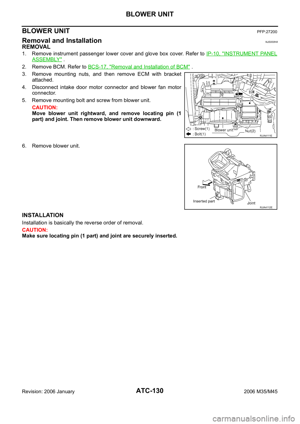
3. Remove mounting nuts, and then remove ECM with bracket
attached.
4. Disconnect intake door motor connector and blower fan motor
connector.
5. Remove mounting bolt and screw from blower unit.
CAUTION:
Move blower unit rightward, and remove locating pin (1
part) and joint. Then remove blower unit downward.
6. Remove blower unit.
INSTALLATION
Installation is basically the reverse order of removal.
CAUTION:
Make sure locating pin (1 part) and joint are securely inserted.
R J I A 4 111 E
RJIA4112E